UDDEHOLM ORVAR® 2 MICRODIZED
© UDDEHOLMS AB No part of this publication may be reproduced or transmitted for commercial purposes without permission of the copyright holder.
This information is based on our present state of knowledge and is intended to provide general notes on our products and their uses. It should not therefore be construed as a warranty of specific properties of the products described or a warranty for fitness for a particular purpose. Classified according to EU Directive 1999/45/EC For further information see our “Material Safety Data Sheets”. Edition 5, 05.2013 The latest revised edition of this brochure is the English version, which is always published on our web site www.uddeholm.com
2
SS-EN ISO 9001 SS-EN ISO 14001
UDDEHOLM ORVAR 2 MICRODIZED
General
Application
Uddeholm Orvar 2 Microdized is a chromiummolybdenum-vanadium-alloyed steel which is characterized by: • good resistance to abrasion at both low and high temperatures
Tools for extrusion
• high level of toughness and ductility • uniform and high level of machinability and polishability • good high-temperature strength and resistance to thermal fatigue
Part Dies Backers, dieholders, liners, dummy blocks, stems Austenitizing temperature (approx.)
Aluminium, magnesium alloys, HRC
Copper alloys HRC
Stainless steel HRC
44–50
43–47
45–50
41–50 1020–1030°C (1870–1885°F)
40–48
40–48
1040–1050°C (1900–1920°F)
• excellent through-hardening properties • very limited distortion during hardening. Si 1,0
Mn 0,4
Cr 5,3
Mo 1,3
Plastic moulding applications
Typical analysis %
C 0.39
V 0,9
Standard specification
AISI H13, W.-Nr. 1.2344, EN X40CrMoV5-1
Delivery condition
Soft annealed to approx. 185 HB
Colour code
Orange/violet
Part Injection moulds Compression/ transfer moulds
Austenitizing temp. (approx.)
HRC
1020–1030°C (1870–1885°F) or 550–580°C (1020–1080°F)
48–50
Other applications Application
Austenitizing temp. (approx.)
HRC
Severe cold punching, scrap shears
1020–1030°C (1870–1885°F) Tempering 250°C (480°F)
50–52
1020–1030°C (1870–1885°F) Tempering 250°C (480°F) or 575–600°C (1070–1110°F)
50–52 45–50
1020–1030°C (1870–1885°F) Tempering 575–620°C (1070–1110°F)
45–50
Hot shearing
Shrink rings (e.g. for cemented carbide dies) Wearresisting parts
1020–1030°C (1870–1885°F) In core Tempering 575°C (1070°F) 50–52 Nitriding On surface ~1000 HV1
For applications requiring extreme levels of toughness and ductility e.g. die casting dies, forging dies, the premium grade H13-steel, Uddeholm Orvar Supreme, is recommended.
3
UDDEHOLM ORVAR 2 MICRODIZED
Properties
Heat treatment
Physical data
Soft annealing
Unless otherwise is indicated all specimens were hardened 30 minutes at 1025°C (1875°F), quenched in air and tempered 2 + 2 h at 610°C (1130°F). The hardness were 45 ± 1 HRC.
Protect the steel and heat through to 850°C (1560°F). Then cool in the furnace at 10°C (20°F) per hour to 650°C (1200°F), then freely in air.
Temperature Density kg/m3 lbs/in3 Modulus of elasticity N/mm2 psi
20°C (68°F)
400°C (750°F)
600°C (1110°F)
7800 0.281
7700 0.277
7600 0.274
210 000 30.5 x 10⁶
180 000 26.1 x 10⁶
140 000 20.3 x 10⁶
– –
12.6 x 10⁻⁶ 7.0 x 10⁻⁶
13.2 x 10⁻⁶ 7.3 x 10⁻⁶
25 176
29 204
30 211
Coefficient of thermal expansion per °C from 20°C per °F from 68°F Thermal conductivity W/m °C Btu in/(ft2h°F)
stress relieving After rough machining the tool should be heated through to 650°C (1200°F), holding time 2 hours. Cool slowly to 500°C ( 930°F), then freely in air.
Hardening Pre-heating temperature: 600–850°C (1110– 1560°F), normally in two pre-heating steps. Austenitizing temperature: 1020–1050°C (1870– 1920°F), normally 1020–1030°C (1870– 1885°F). Temperature °C °F 1025 1050
Mechanical properties Approximate tensile strength at room temperature. Hardness
52 HRC
45 HRC
Tensile strength Rm N/mm2 kp/mm2 psi
1820 185 263 000
1420 145 206 000
Yield point Rp0.2 N/mm2 kp/mm2 psi
1520 155 220 000
1280 130 185 000
APPROXIMATE STRENGTH AT ELEVATED TEMPERATURES
Longitudinal direction. psi Rm, Rp0.2 1000x MPa 290 261
2000 1800
232
1600
203
1400
174 145 116 87 58
1200 1000 800 600 400
29
200
Rm Rp0.2
100 210
200 390
300 570
400 750
500 600 700 °C 930 1110 1290 °F
Testing temperature
4
1875 1920
Soaking* time minutes
Hardness before tempering
30 15
53±2 HRC 54±2 HRC
* Soaking time = time at hardening temperature after the tool is fully heated through
Protect the part against decarburization and oxidation during hardening.
UDDEHOLM ORVAR 2 MICRODIZED
CCT GRAPH
Austenitizing temperature 1020°C (1870°F). Holding time 30 °F 2000
°C 1100
1800
1000
1600
Austenitizing temp. 1020°C (1870°F) Holding time 30 min. Ac1 f = 950°C (1740°F)
900 800
Carbides
1400
Ac1 s = 860°C (1580°F)
Pearlite
700
Cooling Hardness Curve HV 10 No.
1200 600 1000 500 800
400
Ms 600
Bainite
300
400
200
200
100
1
1
3
2
10
100 1
6
5
4
1 000
654
2
586
37
3
586
160
4
574
280
5
560
560
6
551
1390
7
517
3220
8
451
8360
Quenching media • High speed gas/circulating atmosphere • Vacuum (high speed gas with sufficient positive pressure). An interrupted quench is recommended where distortion control and quench cracking are a concern • Martempering bath or fluidized bed at 450– 550°C (840–1020°F), then cool in air • Martempering bath or fluidized bed at 180–220°C (360–430°F) then cool in air • Warm oil
10 0.394
1
Seconds
100
10
1,5 0.059
7
10 000
1 000 Minutes
1 0,2 0.0079
8
sec.
1
Martensite
Mf
T800–500
Hours Hours
10 90 3.54
Air coolingofof Aircooling bars,Ø Ø mm mm bars
Ø inch
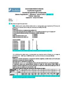
HARDNESS, GRAIN SIZE AND RETAINED AUSTENITE AS FUNCTIONS OF AUSTENITIZING TEMPERATURE Grain size ASTM
Hardness HRC 60
Retained austenite %
Grain size 10
58 56
8 54 6 4
Hardness
52 50
Note 1: Temper the tool as soon as its temperature reaches 50–70°C (120–160°F).
48
Note 2: In order to obtain the optimum properties for the tool, the cooling rate should be fast, but not at a level that gives excessive distortion or cracks.
44
4
42
2
46
40 1000 1830
Retained austenite
1020 1870
1040 1900
6
1060°C 1940°F
Austenitizing temperature
5
UDDEHOLM ORVAR 2 MICRODIZED
Tempering
DIMENSIONAL CHANGES DURING HARDENING
Choose the tempering temperature according to the hardness required by reference to the tempering graph. Temper minimum twice with intermediate cooling to room temperature. Lowest tempering temperature 250°C (480°F). Holding time at temperature minimum 2 h. To avoid “temper brittleness”, do not temper in the range 425–550°C (800–1020°F), see graph.
Sample plate, 100 x 100 x 25 mm, 4” x 4” x 1”.
TEMPERING GRAPH
DIMENSIONAL CHANGES DURING TEMPERING
Hardness, HRC 60 Austenitizing temperature 1050°C (1920°F) 55
50
1020°C (1870°F)
Retained austenite %
1025°C (1875°)
min max
–0.08 –0.15
–0.06 –0.16
0.00 +0.30
Air hardened from 1020°C (1870°F)
min max
–0.02 +0.03
–0.05 +0.02
±0 +0.05
Vac hardened from 1020°C (1870°F)
min max
+0.01 +0.02
–0.02 –0.04
+0.08 +0.12
-0,04 -0,08 -0,12 6
35
4
30
2
100 210
200 300 400 500 600 700°C 390 570 750 930 1110 1290°F Tempering temperature (1h + 1h)
Note: The dimensional changes in hardening and tempering should be added.
Nitriding and nitrocarburizing
25 100 210
200 300 400 500 600 700°C 390 570 750 930 1110 1290°F Tempering temperature (2h + 2h)
Above tempering curves are obtained after heat treatment of samples with a size of 15 x 15 x 40 mm, cooling in forced air. Lower hardness can be expected after heat treatment of tools and dies due to factors like actual tool size and heat treatment parameters.
Tempering within the range 425–550°C (800– 1020°F) is not normally recommended due to the reduction in toughness properties.
EFFECT OF TIME AT TEMPERING TEMPERATURE Hardness, HRC 58 54 500°C (930°F)
50 46 42
550°C (1020°F) Austenitizing temperature 1020°C (1870°F)
600°C (1110°F)
1 1.5 2.5 4 6.5 10 15 25 40 65 100 Total holding time at tempering temperature, hours
6
Oil hardened from 1000°C (1870°F)
+0,04 0
Retained austenite
30
Thickness %
+0,08
40
34
Length %
Dimensional change % +0,12
45
38
Width %
400
Nitriding and nitrocarburizing result in a hard surface layer which is very resistant to wear and erosion. The nitrided layer is, however, brittle and may crack or spall when exposed to mechanical or thermal shock, the risk increasing with layer thickness. Before nitriding, the tool should be hardened and tem-pered at a temperature at least 25–50°C (45–90°F) above the nitriding temperature. Nitriding in ammonia gas at 510°C (950°F) or plasma nitriding in a 75% hydrogen/25% nitrogen mixture at 480°C (895°F) both result in a surface hardness of about 1100 HV0.2. In general, plasma nitriding is the preferred method because of better control over nitrogen potential; in particular, for-mation of the so-called white layer, which is not recommended for hot work service, can readily be avoided. However, careful gas nitriding can give perfectly acceptable results. Uddeholm Orvar 2 Microdized can also be nitrocarburized in either gas or salt bath. The surface hardness after nitrocarburizing is 900–1000 HV0.2.
UDDEHOLM ORVAR 2 MICRODIZED
Drilling
DEPTH OF NITRIDING Process
Time
Depth
Gas nitriding at 510°C
10 h 30 h
0.12 mm 0.20 mm
10 h 30 h
0.12 mm 0.18 mm
2,5 h 1h
0.11 mm 0.06 mm
Plasma nitriding at 480°C
Nitrocarburizing – in gas at at 580°C – in salt bath at 580°C
Nitriding to case depths >0.3 mm (0.012 inch) is not recommended for hot-work applications. Uddeholm Orvar 2 Microdized can be nitrided in the soft-annealed condition. The hardness and depth of case will, however, be reduced somewhat in this case.
HIGH SPEED STEEL TWIST DRILL Drill diameter
Feed, f
inch
m/min
f.p.m.
mm/r
i.p.r.
– 5 5–10 10–15 15–20
–3/16 3/16–3/8 3/8–5/8 5/8–3/4
16–18* 16–18* 16–18* 16–18*
52–59* 52–59* 52–59* 52–59*
0.05–0.15 0.15–0.20 0.20–0.25 0.25–0.35
0.002–0.006 0.006–0.008 0.008–0.010 0.010–0.014
* For coated HSS drill vc = 28–30 m/min. (92–98 f.p.m.)
CARBIDE DRILL Type of drill Cutting data parameters
Indexable insert
Solid carbide
Carbide tip1)
Cutting speed (vc) m/min f.p.m.
220–240 720–785
130–160 425–525
80–110 260–360
Feed (f) mm/r i.p.r.
Machining recommendations
Cutting speed, vc
mm
0.03–0.122) 0.08–0.203) 0.15–0.254) 0.001–0.0052) 0.003–0.0083) 0.006–0.0104)
1)
Drill with replaceable or brazed carbide tip Feed rate for drill diameter 20–40 mm (0.8”–1.6”) 3) Feed rate for drill diameter 5–20 mm (0.2”–0.8”) 4) Feed rate for drill diameter 10–20 mm (0.4”–0.8”) 2)
The cutting data below are to be considered as guiding values, which must be adapted to existing local conditions. More information can be found in the Uddeholm publication “Cutting data recommendations”.
Milling FACE AND SQUARE SHOULDER MILLING
Condition: Soft annealed to approx. 185 HB
Milling with carbide Cutting data parameters
Turning Turning with carbide Cutting data parameters Cutting speed (vc) m/min f.p.m. Feed (f) mm/r i.p.r. Depth of cut (ap) mm inch Carbide designation ISO US
Rough turning
Fine turning
Turning with high speed steel Fine turning
200–250 200–250 656–820
250–300 250–300 820–984
25–30 25–30 82–98
0.2–0.4 0.008–0.016
0.05–0.2 0.05–0.3 0.002–0.008 0.002–0.01
2–4 0.08–0.16
0.5–2 0.02–0.08
0.5–3 0.02–0.12
P20–P30 C6–C5 Coated carbide
P10 C7 Coated carbide or cermet
– –
Cutting speed (vc) m/min f.p.m. Feed (fz) mm/tooth inch/tooth Depth of cut (ap) mm inch Carbide designation ISO US
Rough milling
Fine milling
180–260 591–853
260–300 853–984
0.2–0.4 0.008–0.016
0.1–0.2 0.004–0.008
2–5 0.08–0.2
–2 –0.08
P20–P40 P10–P20 C6–C5 C6–C7 Coated carbide Coated carbide or cermet
7
UDDEHOLM ORVAR 2 MICRODIZED
END MILLING Type of end mill Carbide indexable High insert speed steel
Cutting data parameters
Solid carbide
Cutting speed (vc) m/min f.p.m.
160–200 525–660
Feed (fz) mm/tooth inch/tooth
2)
35–401) 115–1301)
0.03–0.202) 0.08–0.202) 0.05–0.352) 0.001–0.0082) 0.003–0.0082) 0.002–0.0142)
Carbide designation ISO 1)
170–230 560–755
–
P20, P30
Welding Welding of tool steel can be performed with good results if proper precautions are taken regarding elevated temperature, joint preparation, choice of consumables and welding procedure. Welding method Working temperature
MMA
min. 325°C (min. 620°F)
min. 325°C (min. 620°F)
Filler metal
QRO 90 TIG-WELD QRO 90 WELD DIEVAR TIG-WELD UTP 673
Cooling rate
20–40°C/h (35–70°F/h) the first 2–3 h then freely in air.
–
For coated HSS end mill vc = 55–60 m/min. (180–195 f.p.m.) Depending on radial depth of cut and cutter diameter
TIG
Hardness after welding
48–53 HRC
48–53 HRC 55–58 HRC (673)
Heat treatment after welding:
Grinding A general grinding wheel recommendation is given below. More information can be found in the Uddeholm brochure “Grinding of Tool Steel” and can also be obtained from the grinding wheel manufacturer. Type of grinding Face grinding straight wheel Face grinding segments Cylindrical grinding Internal grinding Profile grinding
Soft annealed condition
Hardened condition
A 46 HV
A 46 HV
A 24 GV A 46 LV A 46 JV A 100 KV
A 36 GV A 60 KV A 60 IV A 120 KV
Hardened condition Soft annealed condition
Temper at 10–20°C (20–35°F) below the original tempering temperature. Soft-anneal the material at 850°C (1560°F) in protected atmosphere. Then cool in the furnace at 10°C (20°F) per hour to 650°C (1200°F) then freely in air.
More detailed information can be found in the Uddeholm brochure “Welding of Tool Steel”.
Polishing Uddeholm Orvar 2 Microdized exhibits good polishability in the hardened and tempered condition. Polishing after grinding can be effected using aluminium oxide or diamond paste.
Electrical-discharge machining
Typical procedure: 1. Rough grinding to 180–320 grain size using a wheel or stone.
If spark-erosion is performed in the hardened and tempered condition, the white re-cast layer should be removed mechanically e.g. by grinding or stoning. The tool should then be given an additional temper at approx. 25°C (50°F ) below the previous tempering temperature.
2. Fine grinding with abrasive paper or powder down to 400–800 grain size.
Hard-chromium plating After plating, parts should be tempered at 180°C (360°F) for 4 hours within 4 hours of plating to avoid the risk of hydrogen embrittlement.
8
3. Polish with diamond paste grade 15 (15µm grain size) using a polishing tool of soft wood or fibre. 4. Polish with diamond paste 8–6–3 (8–6–3µm grain size) using a polishing tool of soft wood or fibre. 5. When demands on surface finish are high, grade 1 (1µm grain size) diamond paste can be used for final polishing with a fibre polishing pad.
UDDEHOLM ORVAR 2 MICRODIZED
Photo-etching Uddeholm Orvar 2 Microdized is particularly suitable for texturing by the photo-etching method. Its high level of homogeneity and low sulphur content ensures accurate and consistent pattern reproduction.
Further information Please contact your local Uddeholm office for further information on the selection, heat treatment, application and availability of Uddeholm tool steel.
9
UDDEHOLM ORVAR 2 MICRODIZED
ELECTRIC ARC FURNACE
ESR-PLANT
UPHILL CASTING
HEAT TREATMENT
ROLLING MILL FORGING
MACHINING
STOCK
The ESR Tool Steel Process The starting material for our tool steel is carefully selected from high quality recyclable steel. Together with ferroalloys and slag formers, the recyclable steel is melted in an electric arc furnace. The molten steel is then tapped into a ladle. The de-slagging unit removes oxygen-rich slag and after the de-oxidation, alloying and heating of the steel bath are carried out in the ladle furnace. Vacuum degassing removes elements such as hydrogen, nitrogen and sulphur.
removing macro segregation. Melting under a protective atmosphere gives an even better steel cleanliness. HOT WORKING From the ESR plant, the steel goes to the rolling mill or to our forging press to be formed into round or flat bars. Prior to delivery all of the different bar materials are subjected to a heat treatment operation, either as soft annealing or hardening and tempering. These operations provide the steel with the right balance between hardness and toughness. MACHINING
ESR PLANT In uphill casting the prepared moulds are filled with a controlled flow of molten steel from the ladle. From this, the steel can go directly to our rolling mill or to the forging press, but also to our ESR furnace where our most sophisticated steel grades are melted once again in an electro slag remelting process. This is done by melting a consumable electrode immersed in an overheated slag bath. Controlled solidification in the steel bath results in an ingot of high homogeneity, thereby
10
Before the material is finished and put into stock, we also rough machine the bar profiles to required size and exact tolerances. In the lathe machining of large dimensions, the steel bar rotates against a stationary cutting tool. In peeling of smaller dimensions, the cutting tools revolve around the bar. To safeguard our quality and guarantee the integrity of the tool steel we perform both surface- and ultrasonic inspections on all bars. We then remove the bar ends and any defects found during the inspection.
Network of excellence UDDEHOLM is present on every continent. This ensures you high-quality Swedish tool steel and local support wherever you are. ASSAB is our exclusive sales channel, representing Uddeholm in the Asia Pacific area. Together we secure our position as the world’s leading supplier of tooling materials.
www.assab.com
www.uddeholm.com
UDDEHOLM 130501.150 / STROKIRK KNAPPEN 201305
UDDEHOLM is the world’s leading supplier of tooling materials. This is a position we have reached by improving our customers’ everyday business. Long tradition combined with research and product development equips Uddeholm to solve any tooling problem that may arise. It is a challenging process, but the goal is clear – to be your number one partner and tool steel provider. Our presence on every continent guarantees you the same high quality wherever you are. ASSAB is our exclusive sales channel, representing Uddeholm in the Asia Pacific area. Together we secure our position as the world’s leading supplier of tooling materials. We act worldwide, so there is always an Uddeholm or ASSAB representative close at hand to give local advice and support. For us it is all a matter of trust – in longterm partnerships as well as in developing new products. Trust is something you earn, every day. For more information, please visit www.uddeholm.com, www.assab.com or your local website.