Loughborough University Institutional Repository
UAV collision avoidance based on geometric approach This item was submitted to Loughborough University's Institutional Repository by the/an author.
Citation: PARK, J.-W., OH, H. and TAHK, M.-J., 2008. UAV collision avoidance based on geometric approach.
IN: Proceedings of the 2008 SICE Annual
Conference, 20th-22nd August 2008, Tokyo, pp. 2122 - 2126.
Additional Information:
c 2008 IEEE. Personal use of this material is permitted. •
Permission from
IEEE must be obtained for all other uses, in any current or future media, including reprinting/republishing this material for advertising or promotional purposes, creating new collective works, for resale or redistribution to servers or lists, or reuse of any copyrighted component of this work in other works.
Metadata Record: https://dspace.lboro.ac.uk/2134/17861 Version: Accepted for publication c SICE Publisher: IEEE /
Please cite the published version.
UAV Collision Avoidance Based on Geometric Approach Jung-Woo Park 1 ,Hyon-Dong Oh 2 and Min-Jea Tahk 3 1,2,3
School of Mechanical, Aerospace and System Engineering, Department of Aerospace Engineering, Korea Advanced Institute of Science and Technology, Daejeon, Korea (Tel: +82-42-869-3758; E-mail: {jwpark; hdoh; mjtahk} @ fdcl.kaist.ac.kr)
Abstract: A method of collision avoidance is described by using simple geometric approach. Two UAVs are dealt with and considered as point masses with constant velocity. This paper discusses en route aircraft which are assumed to be linked by real time data bases like ADS-B. With this data base, all UAVs share the information each other. Calculating PCA (Point of Closest Approach), we can evaluate the worst conflict condition between two UAVs. This paper proposes one resolution maneuvering logic, which can be called ‘Vector Sharing Resolution’. In case of conflict, using miss distance vector in PCA, we can decide the directions for two UAVs to share the conflict region. With these directions, UAVs are going to maneuver cooperatively. First of all, this paper describes some ‘2-D’ conflict scenarios and then extends to ‘3-D’ conflict scenarios. Keywords: Vector Sharing Resolution, Cooperative collision avoidance, Point of Closest Approach (PCA), Sphere protected zone.
1. INTRODUCTION There are many researches for ‘Free Flight’ [1]. Many methodologies and skills are published up to the present. For example, there are many studies accomplished that finding optimal trajectories by using many optimal theories, probabilistic modeling, applying potential field, and so on. ‘Conflict’ can be defined as a “predicted violation of a separation assurance standard” [2]. So if the protected zone is violated, each UAV should solve the violation using proper way to avoid the conflict. For the Free Flight, it is very essential task to understand geometric relations between two UAVs in a conflict. In this paper, using PCA method[3], we calculate the miss distance vector of two UAVs and the time to take. If the magnitude of miss distance vector is smaller than the minimum separation which should be guaranteed, it is considered as a conflict that can bring about collision between UAVs. So this paper discusses a method to resolve the conflict, essentially to avoid the collision between some pair of UAVs by using simple geometric sense.
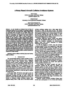
2. SYSTEM MODELING In this paper, two UAVs with constant velocities toward their goal positions are considered in a conflict condition when they are within a protected zone. Generally, aircraft’s ‘Protected Zone’ is currently sized by 5 nmi (about 9.26 km) horizontally and 2000 ft (about 0.61 km) vertically [4], but for the simplistic, it is taken to be a sphere of specified radius about 5 nmi in this paper. Initially the positions and velocities are assumed to be informed by certain broadcasting systems like ADS-B, and the information from such as GPS is assumed to be quite exact. The point-mass equations of motion are derived with respect to a coordinate system shown in Fig. 1. The point-mass UAV equations are:
V =
2
VH + VV
2
(1)
x = VH cos γ , y = VH sin γ , z = V sin θ = VV
(2)
g tan φ VH
(3)
γ=
where θ is UAV’s pitch angle, γ is heading angle, and φ is bank angle. To generate heading angle change, bank command is given as an input, and pitch command is given to generate pitch angle. The detail equations are: 1 φ = ⋅ (φcom − φ ) (4) N 1 θ= ⋅ (θ com − θ ) (5) M The equations consider the delay of actual UAV’s dynamics. It is shown that time constant is assumed to be N and M seconds for both dynamics at Eq. (4) and Eq. (5).
VH A
( xGB , yGB , zGB )
VVA
(xA, yA , zA )
VA VB
VVB VH B
( xGA , yG A , zGA )
( xB , yB , z B )
Fig. 1 Geometric view of basic conception of two UAVs.
The relative distance is simply given as: Rrel =
2
2
( x A − xB ) + ( y A − y B ) + ( z A − z B )
2
(6)
With this relative distance, we can judge whether it is in a conflict condition or not.
VB
−VA
c
r
VA
3. CONFLIICT DETECTION / RESOLUTION It is assumed that two UAVs are in an encounter with each other, and they are heading to their velocity direction which means there’s no sideslip for UAVs. The geometry is illustrated in Fig. 2. 3.1 Conflict Detection When two UAVs are getting closer, if we can calculate the minimum distance passed by each other, it can be judged whether collision can be occurred or not. For this, we can get the miss distance from PCA (Point of Closest Approach). The miss distance vector rm is defined: rm = cˆ × ( r × cˆ)
(7)
where r is the relative distance vector and cˆ is the unit vector in the direction of the relative velocity vector c from UAV ‘A’ to UAV ‘B’. Naturally we can know that the miss vector rm and relative velocity vector c is orthogonal: rm ⋅ c = 0
(8)
With the relation between rm and r , we can calculate the time to closest approach τ : rm = r + c ⋅ τ (9) With Eq. (8) and (9), finally we get: r ⋅c τ =− (10) c ⋅c At the Eq. (10), when two of UAVs are getting closer, τ > 0 , and when two of UAVs are getting further, τ < 0 . Therefore, when τ > 0 , we have to check whether there’s a chance to have an event of conflict or not. When τ < 0 , we can guess that there’s no risk to have an event of collision at all. If the magnitude of rm is less than specified
minimum separation distance rsafe , two UAVs are considered in a conflict condition. - Conflict condition:
rres
= rsafe − || rm ||> 0
where rres is the rest region after subtraction of || rm || from rsafe . rres will be called “Unresolved
Region” in this paper.
Fig. 2 Relative motion of two UAVs. 3.2 Conflict Resolution If rres > 0 , conflict resolution maneuvering should be accomplished. In Fig. 2, we can intuitively know the direction where each of UAVs has to go. UAV ‘A’ may turn to the left to avoid collision and UAV ‘B’ may turn to the left too. It can be easily figured out if we think about the motion of UAVs with respect to the miss distance vector. To larger the miss distance, UAV ‘A’ and ‘B’ have no choice except being headed for left. If UAV ‘A’ makes a turn to the right, it takes a very long distance roundabout way or it collides with UAV ‘B’. The case of UAV ‘B’ is also same logic. To solve this problem, it is proposed that the conflict resolution maneuvering lies on the line of miss distance vector. This will be called as “Vector Sharing Resolution” in this paper and it is described in Fig. 3. In the Fig. 3, to share the unresolved region, two UAVs should at least head for the direction of unit vector U A and U B . This indicates that this logic gives each UAV a least direction to solve the conflict condition. Vector sharing resolution is achieved as defining the vector rVSA and rVSB in Fig. 3:
- For UAV ‘A’ =
| VB |
rres
(− rm )
(12)
(rm )
(13)
rsafe =| rVSA | + | rVSB | + | rm |
(14)
rVSA
| VA | + | VB | | rm |
- For UAV ‘B’ rVSB
=
| VA |
rres
| VA | + | VB | | rm |
- A relation between (11)
rm
rVSA and rVSB
:
By the means of that the slower UAV takes the more sharing, the sharing is done. It is because slower UAV can do avoidance maneuver more than faster one with same time. Finally we get the unit vector U A and U B :
- For UAV ‘A’ UA =
VA | VA
⋅ τ + rVSA
(15)
⋅ τ + rVSA |
- For UAV ‘B’ UB
=
VB | VB
⋅ τ + rVSB
(16)
⋅ τ + rVSB |
3.4.1 Application to the UAV Dynamics With these two vectors we can calculate the LOS (Line Of Sight) angle. For each UAV, the LOS is defined:
⎛ VH ⋅ U H ⎞ ⎟ ⎝ | VH | ⎠
λ = signum((VH × U H ) z ) arccos ⎜
rm rVSB
UB
VB ⋅τ
We know the directions of now-going and modified. Now-going one is the direction of velocity V and modified one is the direction of U .
rVSA
UA
rm
VA ⋅ τ
−rm
Fig. 3 Resolution Maneuvering. If two UAVs are going to have a direct head-on collision ( rm = 0), by disturbance making process we make two UAVs have non-zero miss distance vector. Detail is followed as: V + 0.01 × (h × V ) U = (17) | V + 0.01 × (h × V ) | where h is the unit vector of z-direction. In real flight, by certain maneuver of one of UAVs, this problem can be resolved. Additionally, if it is doubt to the chattering or not complete information from ADS-B, we define certain region to be dealt with as zero miss distance region. 3.3 The Optimal Maneuver to Resolve We can consider the optimal problem to maximize the miss distance at the end of resolution maneuver. 1 2 min J = − | rm | f (18) a 2 where ‘a’ is acceleration vector as input. Then we can derive the equation of Hamiltonian. H = − rf i v − A(t f − t )rf ie (19)
where e is the unit vector of acceleration vector. Therefore we conclude that acceleration along the miss distance vector can minimize the Hamiltonian so that it can be the optimal solution.[5] This is not sudden result. With the protected zone of sphere it is most efficient to avoid each other along the miss distance vector since the miss distance vector is perpendicular to the velocity vector so that it maximize the miss distance with same acceleration to apply the acceleration to the direction miss distance vector line. 3.4 Application to the UAV Dynamics
(20)
where subscript ‘H’ means horizontal element. By the LOS angle found we decide the bank command as an input. It is assumed that each UAV has its maximum bank angle of 45 degree. So with the maximum bank angle, we can calculate the maximum heading angle change for 1 second: g γ max = , for 1 second and φmax (21) | VH | where g is the gravity acceleration and VH is the horizontal velocity. Keeping on this result, the horizontal maneuver logic is followed as: Table 1 The Horizontal Maneuver Options.
Range of LOS angle
Bank Command
λ < −γ max
φcom = −45°
−γ max
≤ λ ≤ γ max
γ max < λ
φcom =
λ γ max
× 45°
φcom = 45°
An UAV can change the bank angle easily, so we set the time constant N of 1 second in Eq. (4). 3.4.2 Application to the UAV Dynamics With unit vector U for each UAV, we can obtain the pitch angle required. Required pitch angle can be expressed as: ⎛ U ⎞ (22) θ req = arctan ⎜ V ⎟ ⎝ | UH | ⎠ Vertical motion is hard to change fast. So we have to deal with the change of pitch angle carefully. At the vertical maneuver, we set the time constant of M in Eq. (5) by the required pitch angle. Vertical maneuver logic is followed as:
Table 2 The Vertical Maneuver Options. Time constant, M Required pitch angle 0° < | θ req | < 15°
1 second
15° < | θ req | < 30°
2 seconds
30° < | θ req | < 45°
3 seconds
| θ req | > 45°
4 seconds
As pitch angle changes, the horizontal velocity and the vertical velocity also change. The velocity element change is described as: | VV |=| V | sin θ and | VH |=| V | cos θ (23)
4. NUMERICAL RESULTS The conflict detection and resolution algorithm discussed in previous sections are evaluated in two sample encounter scenario in this section. Simulation has been accomplished with initial information about position and velocity for both UAVs. Two UAVs are assumed to head toward their goal position. And the integrated positions and velocities have been treated as broadcasted information. Minimum separation distance is 5 nmi (about 9.26 km) as defined. Also it is assumed that the interval for updating the information from ADS-B is 1 sec. Between the intervals, UAVs maneuver with the commands for bank and pitch during 1 sec. It is for the consistent maneuvering not to change the bank and pitch angle suddenly during the conflict resolution. All simulations for 2-D and 3-D are accomplished assuming all scenarios are non-cooperative cases since it is easier to avoid each other cooperatively so that the non-cooperative maneuver guarantees the successful conflict resolution of the cooperative cases. 4.1 ‘2-D’ Conflict Scenario
Table 3 Problem Definition for ‘2-D’. Initial Position (0,0,0) km Initial Velocity (150,150,0) m/s UAV ‘A’ Goal position (75,75.,0) km Initial Position (0,100,0) km Initial Velocity (150,-145,0) m/s UAV ‘B’ Goal position (75,27.5,0) km - Results for ‘2-D
Fig. 5 Relative distance.
Fig. 6 Bank angle profile for Own UAV. Own UAV turns to the right to avoid the conflict. Trajectory is expected pattern and the relative distance also never invades the minimum separation region. On the way to the guidance for homing, avoidance guidance is applied. During the homing guidance, the sudden angle(bank) change occurs. But it can be modified in real by using PNG guidance. 4.2 ‘3-D’ Conflict Scenario
Table 4 Problem Definition for ‘3-D’. Initial Position (0,0,0) km Initial Velocity (150,100,10) m/s UAV ‘A’ Goal position (30,20,2) km Initial Position (30,0,0) km Initial Velocity (-150,90,10) m/s UAV ‘B’ Goal position (0,18,2) km - Results for ‘3-D
Fig. 4 Trajectories of both UAVs.
Fig. 7 Trajectories of both UAVs.
study starts with the calculation of miss distance from PCA. In case of pair-wise conflict resolution, the UAV just maneuvers with the commend to resolve the conflict region directly. However, in case of multiple conflict resolution, all trajectories of UAVs should be dealt with.
Fig. 8 Relative distance.
Fig. 10 Conception of multiple conflict resolution.
Fig. 9 Bank angle profile for Own UAV. From the simulation, we can see that horizontal and vertical maneuvers work well. In Horizontal, own UAV turn to the left and changes the altitude down. These results are also expected pattern to resolve the conflict effectively.
5. CONCLUSION Collision avoidance can be done by accomplishing the conflict resolution algorithm described in this study. Keeping and not losing the minimum separation distance, we settle up the conflict between UAVs. There are methodologies and skills developed to avoid the conflict. The geometric approach is also one of the ways. In this paper, using geometric method, the conflict resolution maneuver is accomplished successfully. Using PCA method, the algorithm for conflict detection and resolution is induced by intuition simply. But there are still tasks to solve in the future. This paper deals with simple dynamics for the UAVs. More realistic and well approached dynamics are needed, especially in the pitch dynamics. And multiple collision avoidance algorithm should be issued. Even though vector sharing resolution is one of many resolution algorithms for collision avoidance, it gives just one possibility to resolve the conflict.
6. FUTURE WORK One conception is considered for the multiple collision avoidance. The algorithm described in this
In the Fig. 10, the stream vectors for own UAV are described. Both drawings are at the time when the closest intruder is faced with. In the first case(left), own UAV can resolve all conflict with all intruders one by one by applying the algorithm for the pair-wise conflict resolution. But, in the second case(right), own UAV should consider all intruders at the same time since own UAV cannot resolve the conflict by using pair-wise conflict resolution algorithm. Therefore in that situation, first, we calculate the artificial center of two intruders, second, consider two intruders as one intruder and, finally, apply the algorithm as described in this paper. Then, the global conflict resolution is accomplished. For multiple conflict resolution, the rate of updating the information from ADS-B should be fast and own UAV may maneuver agilely. More the intruders are, more complicated algorithm should be considered. Therefore the progress for multiple conflict resolution should be dealt with carefully, and the enough evaluation is needed. It is the direction of this study.
REFERENCES [1] Lee C. Yang and James K. Kuchar, “Prototype Conflict Alerting System for Free Flight”, American Institute of Aeronautics and Astronautics, Inc., 1997. [2] Wallace E. Kelly III, Rockwell Collins, Cedar Rapids, and Iowa, “Conflict Detection and Alerting for Separation Assurance Systems”, Digital Avionics Systems Conference, St. Louis, 1999. [3] Jimmy Krozel and Mark Peters, “Strategic Conflict Detection and Resolution for Free Flight”, Seagull technology, Inc., 1997. [4] Douglas R. Isaacson and Heinz Erzberger, “Design of A Conflict Detection Algorithm for The Center/Tracon Automation System”, NASA Ames Research Center, 1997. [5] A.W.MERZ, “ Maximum-Miss Aircraft Collision Avoidance”, Dynamics and Control, Vol. 1, pp. 25-34, 1991.