2002-01-0065
Three-Dimensional Simulation of the Transient Behavior of a Three-Way Catalytic Converter Joachim Braun, Thomas Hauber, Heike Többen, Julia Windmann, Peter Zacke J. Eberspächer GmbH & Co.
Daniel Chatterjee1, Chrys Correa2, Olaf Deutschmann, Lubow Maier, Steffen Tischer, Jürgen Warnatz University of Heidelberg Copyright © 2002 Society of Automotive Engineers, Inc.
ABSTRACT INTRODUCTION The ultimate goal in the numerical simulation of automotive catalytic converters is the prediction of exhaust gas emissions as function of time for varying inlet conditions, i.e. the simulation of a driving cycle. Such a simulation must include the calculation of the transient three-dimensional temperature-field of the monolithic solid structure of the converter, which results from a complex interaction between a variety of physical and chemical processes such as the gaseous flow field through the monolith channels, the catalytic reactions, gaseous and solid heat transport, and heat transfer to the ambience. This paper will discuss the application of the newly deMONOLITH for the numerical veloped CFD-code DETCHEM simulation of the transient behavior of three-way catalytic converters that have a monolithic structure. The code combines the two-dimensional simulations of the reactive flows in a representative number of monolith channels with a transient simulation of the three-dimensional temperature field of the solid structure of the converter including insulation and canning. The chemical reactions are modeled by a multi-step heterogeneous reaction mechanism, which is based on the elementary processes on the platinum and rhodium catalysts used. The integration over the chemical conversion in the single channels leads to the total conversion in the converter as function of time. This paper presents a numerical simulation of the startup phase of an automotive catalytic converter for temporally varying inlet conditions. The variation of the temperature distribution in the solid structure and in the single channels as well as the species profiles are described. The numerically predicted time-dependent conversion of the combustion pollutants is compared with experimental data. The potentials and limitations of the models and computational tools are discussed. 1 2
now DaimlerChrysler AG, Stuttgart now BASF AG, Ludwigshafen
In the automotive industry, the development cycles are continuously reduced, whereas the guidelines of the legislation concerning the pollutant emission limits become more restrictive. The legislatively enforced emission limits can only be fulfilled by the optimization of the exhaust gas system. Not only the right choice of the single components but also their arrangement is important. Mathematical modeling and numerical simulation has been gaining significance in the design and optimization process, as extensive experimental setups are not only time consuming but also expensive. The numerical simulation of the exhaust system can already support catalyst design in an early stage of development. For the three-way catalyst, the major concern here is the correct prediction of the light-off behavior of the exhaust system, because the pollutant emitted in this period presents a large amount of the overall pollutant emission during the driving test cycle given by legislation. In order to achieve reliable results, the numerical simulations have to be based on accurate models of all the significant chemical and physical processes in the catalytic converter. In the last years, several models were proposed for the numerical simulation of catalytic converters /1-4/ reaching from a one-dimensional up to a three-dimensional description of the temperature distribution in the monolith. Most of these studies have in common, that they use global reaction kinetics for the description of the chemical reactions. Alternatively, the chemical reaction system can be described by a multi-step reaction mechanism based on the elementary steps occurring on a molecular level on the catalytic surface /5-7/. This approach requires more computational efforts because a large number of chemical species and reactions is considered. In
particular, the description of the surface coverage of the catalyst with adsorbed species and the strongly nonlinear reaction kinetics lead to a highly-nonlinear, stiff differential-algebraic equation system. Simultaneously, the modeling effort demands the knowledge of the reaction scheme and the rate coefficients for every single step. However, the effort is rewarded by the fact that the simulation can not only describe the system but also predict the system behavior under varying external conditions, which not have necessarily been investigated by experiments a priori. Therefore, such detailed models will lead to more accurate transient simulations of the behavior of an automotive catalytic converter. This study continues our former work on modeling automotive catalytic converters /5/, in which steady-state simulations of the conversion process in a single monolith channel at constant channel wall temperature were carried out. Now we study the transient behavior of the entire monolith. In that former study, we used a sample gas containing the pollutants CO, NO, and C3H6 in the experiment and the simulation. Additionally, in the current simulation, CH4 is considered as additional hydrocarbon species in order to map the behavior of a real exhaust gas. In the experiment, a real exhaust gas mixture coming from an SI engine is used. Earlier simulations used FLUENT /8/ to calculate the reactive flow field in the channels. Those simulations were very time consuming and not well suited for a transient simulation of the catalytic converter. In order to speed up the single channel simulations, the recently developed CHANNEL /9-11/ was used. It computer program DETCHEM solves the steady-state two-dimensional reactive flow in a straight channel based on a boundary-layer code and takes heterogeneous reactions into account. The time-dependend temperature distribution in the twoor three-dimensional monolith structure is calculated by MONOLITH_2D MONOLITH_3D or DETCHEM , the code DETCHEM respectively /10,11/. These codes are coupled with CHANNEL to account for the behavior in the DETCHEM MONOLITH codes can also single channels. The DETCHEM be linked to input/output data structures of the CFD-code FLUENT, which can be used to simulate the flow in front of and behind the converter. In the present paper, we performed a numerical simulation of the start-up phase of an automotive catalytic converter for time varying inlet conditions. The variation of the temperature distribution in the solid structure and in the single channels as well as the species profiles are described. The numerically predicted time-dependent conversion of the combustion pollutants is compared with experimental data. The potentials and limitations of the models and computational tools are discussed.
MATHEMATICAL AND NUMERICAL MODEL The numerical model for the simulation of the monolith consists of two parts. Since the time scales of the re-
active channel flows and of the solid's thermal response are decoupled, time variations in the local monolith temperature can be neglected when calculating the fluid flow through a single channel. Thus, a time independent formulation is used to describe the gaseous flow in order to calculate heat source terms for a transient heat conduction equation for the solid /12/. CHANNEL
models a single channel with cylinDETCHEM drical symmetry. Since the variation of the washcoat thickness over the channel walls has not been determined and a comparison with three-dimensional single channel simulations revealed only minor differences, a cylindrical channel model assuming a mean channel diameter and washcoat thickness was used. Given the inlet (velocity, temperature, density, species mass fractions) and wall conditions (axial temperature profile), the two-dimensional flow field of the fluid can be solved. The set of Navier-Stokes equations is the most accurate model for the description of the laminar flow of a chemically reacting fluid. However, due to their mathematical structure - in the time independent formulation they resemble a set of nonlinear elliptical partial differential equations - and their stiffness, a numerical solution is computationally expensive /13,14/. Therefore, simpler models such as plug-flow or boundary-layer models are frequently used /14,15/. In the boundary layer of a fluid near a surface, the convection is mainly directed parallel to the surface. The diffusive transport in the same direction diminishes in comparison with the one perpendicular to the surface. This effect becomes more significant as the axial gas velocity is increased, i.e. for higher Reynolds numbers as long as the flow is laminar. The results achieved by the boundary-layer model can be as accurate as the results from the full Navier-Stokes model at high but laminar flow rates /12/. Mathematically, the character of the equations changes from elliptical to parabolic with a timelike coordinate along the channel axis. The set of equations consists of conservation equations for Total mass
∂ (rρu ) ∂ (rρv ) + =0 , ∂z ∂r
(1)
Mass of species s
∂ (rρuYs ) ∂ (rρvYs ) ∂ + = − (rjs ) , ∂z ∂r ∂r
(2)
Axial momentum
∂ (rρuu ) ∂ (rρvu ) ∂p ∂ æ ∂u ö , (3) + = −r + ç µr ∂z ∂r è ∂r ∂z ∂r
tool predicts the transient, two- or three-dimensional distributions of temperature and species concentrations.
And Enthalpy
∂ (rρuh) ∂ (rρvh ) + = ∂z ∂r ru
CHEMICAL REACTION SYSTEM ∂p ∂ æ ∂T ö ∂ æç + ç λr ÷− ∂z ∂r è ∂r ∂r çè
rj s h s
ö (4)
s
Given the inlet conditions, the boundary-layer equations are solved in a single sweep of integration along the axial direction by a method-of-lines procedure. The radial derivatives are discretized by a finite-volume method. The resulting differential-algebraic equation system is integrated using the semi-implicit extrapolation solver LIMEX /16/. The transport coefficients for radial diffusion (µ, λ) and the species diffusion flux js depend on temperature and species composition. Surface reaction source terms (js,surface) are modeled by elementary-step based reaction mechanisms as has been described in detail in /5,7,11/. The model of the catalytic reactions on the inner channel wall accounts for a varying surface coverage of adsorbed species along the channel. Furthermore, a model for pore diffusion inside washcoats /17/, which also depends on the local reaction rates, can be included when necessary. MONOLITH_2D
MONOLITH_3D
In DETCHEM or DETCHEM /10,11/, the simulation of the thermal behavior of the entire monolithic structure, which is coupled with the single channel simulations, is modeled by a two- or threedimensional temperature equation, respectively, i. e.
æ λT ö ∂T q . = ∇2 ç + ç ∂t ρC p è ρC p
(5)
The material properties (density ρ, heat capacity Cp and thermal conductivity λ) are functions of the local temperature and material (monolith, insulation and canning) and can also be specified as functions of the direction. Heat losses due to conduction, convection, and thermal radiation at the exterior walls of the monolith can be included. In order to obtain the source terms q in the temperature equation, the heat flux from the gas phase into the monolith bulk due to convection and chemical heat release is calculated for a representative number of channels. These single-channel simulations are carried out for each time step of the transient temperature simulation. They apply the actual local axial temperature profiles as boundary conditions and use the timedependent initial flow conditions. Hence, time-varying inlet conditions can be specified as long as the conditions vary at a time scale that is larger than the residence time. For the spatial discretization of the transient temperature equation, a finite volume approach is used. For the integration of the resulting ordinary differential equation system one of the solvers LIMEX /14/ or LSODE /18/ can be chosen from. Based on these models, the computational
A detailed multi-step reaction mechanism is used to model the catalytic reactions in a three-way catalytic converter that contains Pt and Rh as active catalysts. The surface coverage of the species on the catalytic material and the surface mass fluxes are also calculated as a function of the position in the channel. This approach has already been discussed in former publications /5,7,11/. The mechanism includes only surface chemistry; gas phase chemistry can be neglected because of the low pressure and temperature, and the short residence time. In the simulation, the sample exhaust gas mixture is composed of C3H6, CH4, CO2, H2O, CO, NO, O2, N2. The surface reaction scheme consists of 62 reaction steps among the 8 gas phase and further 29 adsorbed chemical species. It is assumed that all species are adsorbed competitively. The model also considers the different adsorption sites (platinum or rhodium) on the metallic catalyst surface. However, on rhodium, surface reactions are considered between NO, CO, and O2 only. The kinetic data of the mechanism were taken either from literature or fits to experimental data. The mechanism is based on our former studies /5,7/. Here it was slightly extended by the introduction of CH4 reactions on the platinum surface. The revised mechanism will be discussed in a forthcoming paper, when further experimental measurements and numerically predicted data are available for the validation of the mechanism. The parameters of the catalyst used, e.g., metal composition and loading, dispersion, and so on, have taken as described in the preceding paper /5/; the experiment is carried out using the same catalyst. In the simulation, a simplified washcoat model is used with CO as species that determines the effectiveness factor /5,11/.
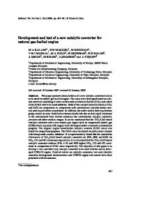
EXPERIMENTAL SETUP For this study, experiments were carried out on an engine test bench. A 4-cylinder 1.6 l SI engine was used, which meets the EU-III pollutant emission standards. The design of the exhaust system was chosen in a way that guarantees a highly uniform flow distribution in front of the catalytic converter. Therefore, the exhaust system was provided with a long straight pipe and a long inlet cone before the monolith as shown in Figure 1. A commercially available three-way catalyst was used, 3 containing 50 g/ft noble metal (Pt/Rh = 5:1) impregnated on a ceria stabilized γ-alumina washcoat. The washcoat was supported by a race-track shaped cordierit monolith with the dimensions 169.7 x 80.8 x 114.4 mm (6.68" x 2 3.18" x 4.5"), a cell density of 63 cells per cm (400cpsi) and a wall thickness of 0.165 mm (6.5 mil). The length of the catalytically active monolith was varied keeping the
total length constant. The results, presented in this study, were obtained with a catalytic converter of 57.2 mm (2.25") in length. The surface temperature was measured at 8 points and gas-phase temperature was measured at 3 points along the exhaust system. The gas temperature was measured by 1.5 mm K type thermocouple wires. The mass flow rate was determined at the intake and converted to the corresponding data in front of the catalytic converter. Samples of the gas composition were taken at two positions as shown in Figure 1. The gas samples were then led through heated pipes to an exhaust gas analysis system from HORIBA /19/. The gas components CO, CO2, NOx, O2, and THC were detected. The sampling rate of all data was 1 Hz.
gas phase temperature. Figure 4 shows not only the measured inlet and outlet gas temperature but also the corrected gas inlet temperature and the numerically predicted average gas-phase temperature at the catalyst exit. The species concentrations at the monolith inlet were chosen according to the experimental data measured 5 cm in front of the straight pipe (Figure 1). The unburnt hydrocarbons were distributed among C3H6 (95% C mol) and CH4 (5% C -mol), neglecting the fact that the composition of the exhaust gas is much more complex /20/. This real gas effect is studied in on-going research. Due to the fact that the model does not include oxygen storage effects (see also paragraph Outlook) and stoichiometric conditions were assumed, the oxygen concentration at the inlet was adjusted to unity redox ratio /5/. Thermal convection and radiation at the exterior walls was taken into account, when calculating the temperature distribution in the entire monolith. The emissivity of the external surface of the catalytic converter was assumed as 0.8. Convection was taken into account by a 2 heat transfer coefficient of 80 W/m K.
Figure 1 Sketch of the experimental set-up
The material properties were determined by experiments (thermal conductivity of the monolithic structure) or taken from the literature and product information from the manufacturers.
RESULTS AND DISCUSSION INLET AND BOUNDARY CONDITIONS As an example, the experimental and numerical study of the cold start-up phase of a commercial three-way catalyst will be discussed. In Figure 2, the recorded profiles of the engine power and the rotational speed are shown. The engine is started at cold state and then phases of full and partial load alternate. The corresponding mass flow rate was used to determine the axial inlet velocity at the front of the catalytic monolith, both shown in Figure 3. According to the experimental setup, the flow distribution was assumed to be spatially constant, even though the computational tool can handle spatially varying flow distributions at the monolith inlet. The inlet velocity was calculated on basis of the mass flow rate. Here, it was accounted for the density variation due to the higher gas temperatures and increase in volume by the combustion process. The gas temperature, measured in front of the catalytic converter, was chosen as inlet temperature for the simulation. However, due to the thermal mass and thereby slow thermal response of the chosen thermocouples, a reverse transformation was applied to the temperature signal in order to approximate the actual
Figure 2 Engine torque and rotational speed profiles
At the early stage of operation, the heat is primarily provided by the heat capacity of the incoming exhaust gas. Heat release due to chemical reactions does not play a significant role, which is also revealed by the conversion as shown in Figures 20 – 23. After the converter has reached its operating temperature, the exit gas temperature exceeds the incoming gas temperature (Figure 4) caused by exothermic reactions. In Figure 10 simulation results of the 2D and the 3D model are contrasted. As the presented cross-section of the 3D simulation result implies the maxim radius of the elliptic profile (maximum diameter: 169.7 mm), but the 2D model is based on the mean diameter of the monolith (mean diameter: 122.9mm), the radial ranges differ. The simulation results correspond very well. Figure 3 Mass flow rate at the inlet manifold and velocity magnitude before the catalytic converter
Figure 4 Measured and calculated temperature data: measured gas temperature before catalytic converter (o) measured gas temperature after catalytic converter (x) approximated actual inlet gas temperature (- ⋅ ⋅ -) calculated gas temperature after catalytic converter ()
TEMPERATURE PROFILES Using the computational tools and these inlet and boundary conditions, the transient behavior of the catalyst monolith was simulated for a cylindrical converter with elliptical cross-section as illustrated in Figure 5. MONOLITH_3D DETCHEM is also capable of modeling converters with more complex cross-section. Figures 6 – 9 reveal the solid phase temperature distribution of the monolith including insulation and canning at times of 10 and 41 seconds after start-up, respectively. The incoming hot exhaust gas heats up the monolithic structure. At the exterior wall, steep temperature gradients occur due to external heat loss. However, these gradients mainly occur inside the insulation and canning. Hence, the temperature of the catalytic channels vary only slightly over the cross-section.
Figure 5 The 3-dimensional calculation grid. The flow runs in the positive x-direction.
Figure 6 Temperature distribution in parallel slices, 10 seconds after start-up. The flow runs in the positive x-direction that is stretched by a factor of 3 for visual clarity; only the catalytic active part is shown
Figure 8 Temperature distribution in parallel slices, 41 seconds after start-up. The flow runs in the positive x-direction that is stretched by a factor of 3 for visual clarity; only the catalytic active part is shown
Figure 7 Temperature distribution in the monolith 10 seconds after start-up. Cross-section through the 3-dimensional temperature field in x-z-plane. x* is the normalized x-coordinate in the flow direction, r* is the normalized radial coordinate; only the catalytic active part is shown
Figure 9 Temperature distribution in the monolith 41 seconds after start-up. Cross-section through the 3-dimensional temperature field in x-z-plane. x* is the normalized x-coordinate in the flow direction, r* is the normalized radial coordinate; only the catalytic active part is shown
Figure 10: Comparison between the predicted temperature distributions in the monolith 41 seconds after start-up of the 3D (left hand-side) and the 2D simulation (right hand-side). The cross-section for the 3D simulation result is in the x-z-plane, z* is the normalized coordinate in flow direction; only the catalytic active part is shown
Figures 11 – 13 present the two-dimensional gas phase temperature profiles inside a channel located in the center of the monolith. 10 seconds after start-up, an axial temperature variation of approximately 230 K occurs. The hot exhaust gas is cooled down very quickly due to radial heat conduction upon entering the cold monolith. A few seconds later, the axial temperature profile flattens (Figures 8,9 and 12). Here, the monolith structure has almost reached the exhaust gas temperature. At that time, significant chemical conversion has started (Figures 20 – 23). The light–off temperature is already reached and due to the exothermical reactions the gas phase temperature in the channel increases in flow direction.
Figure 11 Temperature distribution in a single channel, 10 seconds after start-up
140 seconds after start-up, the catalyst temperature is sufficient for complete conversion. In the experiment as well as in the simulation (Figure 4), the exit gas temperature exceeds the incoming gas temperature. Here, chemical heat release leads to the temperature increase as the exhaust gas flows through the monolith channels. We are aware of the fact that the predicted temperature difference between the inlet and outlet gas phase temperature does not agree well with the measured temperature difference (Figure 4). Further experimental investigations shall answer the question whether the deviations are due to configuration of measurement or due to discrepancies in simulation parameters.
Figure 12 Temperature distribution in a single channel, 41 seconds after start-up
Figure 13 Temperature distribution in a single channel, 140 seconds after start-up.
Figure 14
C3H6 mass fraction in a single channel, 10s after start-up.
Figure 17
CO mass fraction in a single channel, 10s after start-up.
Figure 15 C3H6 mass fraction in a single channel, 41s after start-up.
Figure 18
CO mass fraction in a single channel, 41s after start-up.
Figure 16 C3H6 mass fraction in a single channel, 140s after start-up.
Figure 19
CO mass fraction in a single channel, 140s after start-up.
CHEMICAL SPECIES PROFILES
Even though, the general trend of the experimentally observed conversion as function of time could be well predicted by the numerical simulation, some deviations occur. The conversion behavior of NO during the first 70 seconds is well predicted, but then the quality of the correlation decreases. This is likely caused by the assumption of unity redox ratio.
The conversion is related to the monolith temperature and the composition of the inlet feed. 10 seconds after start-up, when the catalyst is still cold, almost no chemical reactions take place. Only in the first section of the catalyst, where the temperature is already above 500K, less than 1% of the chemical species are converted on the catalyst. Figures 14 – 19 show the species profiles for C3H6 and CO. Forty-one seconds after start-up, about 50% of the relevant emission species are converted, i.e. the reaction is lit off. A relatively good agreement between measured and calculated conversion is achieved. In Figures 20 – 23 results of the 2D simulation are presented. After light-off, almost complete conversion can be achieved. Now, the conversion is no longer kinetically limited but controlled by mass transport, i.e., diffusion of reactants to the wall and products back into the fluid. Larger radial gradients are developed (Figure 16 and Figure 19).
The experimentally determined decrease of the conversion rate of the hydrocarbon species at about 75 seconds is well matched, but the following increase is over-predicted. This might be a hint that the calculated temperature profile in the monolith is over-predicted, too. This might also be the reason for the over-predicted decrease of the CO conversion rate at 70 seconds and the over-predicted re-increase. The reaction mechanism has been primarily developed using laboratory steady-state experiments with a welldefined simulation gas, including only propane and propylene as unburned hydrocarbons /5, 7, 17/. Methane oxidation on Pt and Rh has already been extensively studied /13,14,21/. However, the complex exhaust gas mixture contains a much wider variety of hydrocarbons.
Figure 20 Measured (x) and numerically predicted () THC conversion.
Figure 23 Measured (x) and numerically predicted () NO conversion.
Their representation by only two simple species may be one source of deviations. The surface reaction mechanism also needs further validation. For instance, no storage model has been implemented yet, as already mentioned. On the experimental side, accurate measurements of the hydrocarbon concentration and composition have turned out to be a challenge.
Figure 21 Measured (x) and numerically predicted () CO conversion.
Figure 22 Measured (x) and numerically predicted () CO2 conversion.
2D VERSUS 3D MONOLITH SIMULATION MONOLITH
The DETCHEM software can be used for the simulation of three- and two-dimensional converter geometries. The computation is time-consuming, especially if a large number of single channels needs to be analyzed to represent the monolith behavior. A typical CPU-time needed for the 3D simulation of the case studied takes about 24 - 48 hours depending on the hardware, if the parallel version of the code is used, in which each channel is simulated on a single processor. Therefore, the question arises whether or not a twodimensional simulation is sufficiently accurate and how many channels need to be simulated. A comparison of a 2D and a 3D simulation concerning the exit exhaust gas temperature is shown in Figure 24. In the 2D simulation the two-dimensional elliptic crosssection was replaced by a single averaged spatial coordinate. In the 2D simulation 3 channels were simulated. A comparison with simulations with more channels showed no qualitative difference to the simulation results presented in this paper. In the 3D simulation only 2 channels were simulated. Over a wide range, the temporal temperature profiles do not show any difference and neither do the total species conversions (not shown here) (see also Figure 10). In case of a non-monotonic temperature profile in radial direction inside the monolith it seems to be necessary to consider a larger quantity of channels. Such intervals can be found at 45 – 55 seconds and 120 – 130 seconds. However for spatially varying inlet conditions, more channels have to be simulated. A two-dimensional model considering more than 2 channels is appropriate in the case discussed in this study, since spatially constant inlet conditions were assumed.
CONCLUSION The recently developed computational tool MONOLITH DETCHEM has been applied for the transient three-dimensional simulation of a cold start-up of an automotive three-way catalytic converter. The numerical code is based on a two-dimensional description (boundary-layer approximation) of the flow field in the single channels of the monolith coupled with a detailed multi-step surface reaction mechanism and a washcoat model. All the models were based on the physical and chemical processes occurring in the catalytic converter. To our knowledge, it is the first time that this detailed approach has been used for the transient numerical simulation of catalytic converters. The simulation describes the heat-up of the catalytic monolith and the onset of the chemical reactions. The predicted time-dependent exit temperature and conversion are compared with experimental data. The light-off behavior is described well, as well as the conversion behavior in general, while deficiencies still exist in the temperature prediction. In the model, major uncertainties still remain concerning the exhaust gas composition and its representation by a limited number of chemical species. Nevertheless, a computational tool is now available that allows predictive numerical simulations of the pollutant emissions during a driving cycle within a passable amount of time. This tool can be used for converter design and optimization. MONOLITH
The inlet conditions for DETCHEM can either be taken from CFD-simulations or experimental data, and thus, the influence of the exhaust system design can be examined. Furthermore, the impact of the velocity distribution in front of the catalytic converter on conversion can be studied. The interactions between the thermal and geometrical properties and the light-off behavior of the monolith can also be examined.
OUTLOOK We are currently working on the following aspects: • Reaction schemes of more complex hydrocarbon species. Detailed gas analyses showed that a wide variety of HC species is present in the exhaust gas /20/. The influence of some of these species on the reaction system in a 3-way catalytic converter will be examined. • Implementation of a model of oxygen storage effects into the numerical codes. Figure 24 Comparison of the outlet fluid temperature for a 2D (- ⋅ -) and a 3D () simulation; for the 3D simulation the coated part only was taken into account. Additionally the considered calculation inlet gas temperature is plotted (⋅⋅⋅⋅)
• Further tests of the surface reaction mechanism, also under transient conditions. • Further improvements of the numerical algorithms (speed-up).
REFERENCES /1/ S.-J. Jeong and W.-S. Kim, "Three-Dimensional Numerical Study on the Use of Warm-up Catalyst to Improve Light-Off Performance"; SAE 2000-01-0207, (2000) /2/ G.C. Koltsakis, P.A. Konstantinidis and A.M. Stamatelos, "Development and application range of mathematical models for 3-way catalytic converters"; Appl. Catal. B: 12, 161 - 191, (1997) /3/ T. Kirchner and G. Eigenberger, "On the dynamic behavior of automotive catalysts"; Catal. Today, 28, 3 (1997) /4/ A. Onorati, G. Ferrari and G. D'Errico, "1D Unsteady Flows with Chemical Reactions in the Exhaust DuctSystem of S.I. Engines: Predictions and Experiments"; SAE 2001-01-0939, (2001) /5/ J. Braun, T. Hauber, H. Többen, P. Zacke, D. Chatterjee, O. Deutschmann and J. Warnatz, "Influence of Physical and Chemical Parameters on the Conversion Rate of a Catalytic Converter: A Numerical Study"; SAE 2000-01-0211, (2000) /6/ S. Sriramulu, P. D. Moore, J.P. Mello and R. S. Weber, "Microkinetics Modeling of Catalytic Converters"; SAE 2001-01-0936, (2001) /7/ D. Chatterjee, O. Deutschmann, J. Warnatz, “Detailed surface reaction mechanism in a three-way catalyst”, Faraday Discussions119 (2001), in press /8/ FLUENT 5.5, Fluent Inc., Lebanon, NH (2001) /9/ S.Tischer and O.Deutschmann, “Modeling of catalytic partial oxidation reactors”, Chem. Eng. Sci.(submitted) /10/ S. Tischer, C. Correa, O. Deutschmann, “Transient three-dimensional simulations of a catalytic combustion monolith using detailed models for heterogeneous and homogeneous reactions”; Catalysis Today (in press) /11/ DETCHEM, Version 1.4.2, O. Deutschmann, C. Correa, S. Tischer, D. Chatterjee, S. Kleditzsch, J. Warnatz, IWR, Universität Heidelberg /12/ R. Jahn, D. Snita, M. Kubicek, M. Marek, “3-D modeling of monolith reactors”, Catalysis Today 38, 39 (1997) /13/ O. Deutschmann and L.D. Schmidt, “Modeling the Partial Oxidation of Methane in a Short-Contact-Time Reactor”, AIChE J. 44, 2465 (1998) /14/ L.L. Raja, R.J. Kee, O. Deutschmann, J. Warnatz and L.D. Schmidt, “A Critical Evaluation of NavierStokes, Boundary-Layer and Plug-Flow Models of the Flow and Chemistry in a Catalytic-Combustion Monolith”, Catalysis Today 59, 47 (2000) /15/ H. Schlichting and K. Gersten, “Boundary-Layer Theory”, 8th ed., Springer-Verlag, Heidelberg (1999) /16/ P. Deuflhardt, E. Hairer and J. Zugk, “One-Step and Extrapolation Methods for Differential-Algebraic Systems”, Num. Math. 51, 501 (1987)
/17/ D. Chatterjee, Modellierung von Autoabgaskatalysatoren, Dissertation (PhD thesis), Naturwissenschaftlich - Mathematische Gesamtfakultät der Ruprecht-Karls-Universität Heidelberg, 2001 /18/ A.C. Hindmarsh, "ODE pack, a systematized collection of ODE solvers", in: Scientific Computing, R.S. Stepleman et al. (eds.), North-Holland, Amsterdam, 1983, pp. 55-64 /19/ MEXA - 7000 - Serie Abgas-Analysesystem Bedienungsanleitung 4. Ausgabe, Version 1.2, HORIBA Europe GmbH, Steinbach / Ts., Germany 1996 /20/ W.O. Siegl, E.W. Kaiser, A.A. Adamczyk, M.T. Guenther, D.M. DiCicco and D. Lewis, "A Comparison of Conversion Efficiencies of Individual Hydrocarbon Species Across Pd- and Pt-Based Catalysts as a Function of Fuel-Air Ratio"; SAE 982549, (1998) /21/ O. Deutschmann, F. Behrendt, and J. Warnatz, „Modelling and Simulation of Heterogeneous Oxidation of Methane on a Platinum Foil“; Catalysis Today 21 (1994), 461
NOTATION cp,i hi h p q jir r T t u v Yi z λ µ ρ
specific heat at constant pressure of species i enthalpy of species i enthalpy of the mixture pressure heat flux diffusive flux radial spatial coordinate temperature time axial velocity radial velocity mass fraction of species i axial spatial coordinate thermal conductivity viscosity density