Section 8
Catalytic Converter Diagnosis
Front O2 Sensor
Sub O2 Sensor
O2 Sensor waveform with ordinary catalyst
Learning Objectives:
1. Determine the condition of the catalytic converter based on data and engine symptoms, and determine appropriate repair.
Engine Control Systems II - Course 874
Section 8
Catalytic Converter Diagnosis Catalytic Converter System
Wall Thickness
HC CO NOx O2
�
�
H2O CO2 N2
Fig. 8-1 TL874f801
Overview
Catalytic converter failures generally fall in the category of physical damage or catalyst failure. Physical damage usually can be visually identified-cracks, dents, etc. Internally, the structure can be cracked, broken, or melted. Where high heat may have lead to catalyst failure, the engine and related systems need to be thoroughly checked. Catalyst performance before OBD II was determined differently in many states by test equipment. OBD II systems can determine catalyst performance. Performance deteriorates in many cases when the catalyst becomes coated with foreign materials. Contaminated fuel, sealants, or coolant can all affect catalyst performance. The sub (S2) O2 sensor is used to adjust the oxygen level in the catalytic converter to achieve the best catalytic converter efficiency possible. As a catalytic converter deteriorates, its ability to store oxygen is also reduced. During conversion, the stored oxygen is rapidly depleted. The sub O2 sensor detects this and, within a very limited range, the ECM will reduce the amount of fuel injected providing more oxygen to converter. Oxygen levels build up, driving the O2 signal downward. At a predetermined point, fuel control will return to stoichiometric A/F Ratio. When this happens, oxygen again will be depleted driving the sub O2 signal upward, and the cycle will repeat itself. The rate at which this cycle repeats depends on how much of the catalyst has deteriorated, engine load, and the amount of correction as determined by the ECM's fuel control programming.
Engine Control Systems II - Course 874
8-1
Section 8
NOTE
• Fuel control by the sub O2 sensor is a very fine adjustment. Its affect on fuel trim and driveability is extremely limited. • The cycling of the sub O2 sensor signal is NOT to produce an averaging of exhaust gases to achieve stoichiometry. • The affect on the A/F sensor is practically impossible to see on the Diagnostic Tester because of the slow data rate, and the speed of fuel correction. The sub O2 response is slower because of the catalytic action and the fact it is an O2 sensor. • The ECM on an A/F sensor equipped engine does try hold the A/F sensor signal at a constant level, but with these sensors there is hysteresis taking place. In other words there is some variation in the signal. This should not be confused with the cycling action found with fuel control programs used with O2 sensor equipped engines. • The specification for the sub O2 sensor signal frequency to set a DTC is going to vary with the certification level of the vehicle- LEV, ULEV, SULEV. It is important to determine why the catalytic converter failed before replacing it.
NOTE
Catalytic Converter Monitor
Catalyst deterioration is determined by monitoring the amount of oxygen in the exhaust stream after the catalytic converter. The actual level of emission gases in the tailpipe is not monitored. The diagnostic system measures the oxygen storage capacity of the catalyst. This is based on the correlation between catalyst conversion efficiency and oxygen storage capacity. Catalyst efficiency is monitored by comparing the pre-catalyst O2 or A/F sensor output signal with the signal received from the post-catalyst O2 sensor. The ECM uses voltage variations between these sensors to measure the catalyst performance. When the converter is operating properly, the post-catalyst sensor is significantly less active than the pre-catalyst sensor. This is because the converter stores and releases oxygen as needed during its reduction and oxidation processes, thus the post-catalyst sensor is exposed to exhaust gases with very little variation in oxygen levels.
8-2
TOYOTA Technical Training
Catalytic Converter Diagnosis
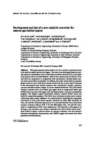
O2 Waveform Normal Operation Catalyst efficiency is monitored by comparing the pre-catalyst O2 or A/F sensor output signal with the signal received from the post-catalyst O2 sensor.
Front O2 Sensor
Sub O2 Sensor
O2 Sensor waveform with ordinary catalyst Fig. 8-2 TL874f802
Main O2 vs. Sub O2 Signal The sub-sensor signal will make slow transitions in voltage, however, they occur over long periods of time (several seconds). The sub-sensor signal from a catalytic converter that is not functioning properly will have a pattern with a frequency and amplitude similar to the main O2 sensor.
Fig. 8-3 TL874f803
Engine Control Systems II - Course 874
8-3
Section 8
A/F Sensor vs. Sub O2 Signal
Waveform of A/F Sensor
Catalyst efficiency is monitored by comparing the pre-catalyst A/F sensor output signal with the signal received from the post-catalyst O2 sensor. The A/F sensor signal does not switch in the same manner as the O2 sensor, therefore the signal will reflect less activity. When the vehicle is accelerated under load with a bad catalytic converter, there will be excess oxygen passing through the converter lowering the sub O2 sensor signal.
NOTE
8-4
Normal Catalyst
Waveform of Heated O2 Sensor behind Catalyst
Abnormal Catalyst
Fig. 8-4 TL874f804
After the engine and catalyst are warmed up and the conditions listed are met, the ECM will run the catalyst monitor. Catalyst warm-up is determined by a calculation in the ECM’s internal programming. Engine load, engine coolant temperature, and time are the primary factors used to determine catalyst temperature.
TOYOTA Technical Training
Catalytic Converter Diagnosis
Catalyst Monitor P0420, P0430
Fig. 8-5 TL874f805
Engine Control Systems II - Course 874
8-5
Section 8
Confirmation Engine Racing Pattern
The Repair Manual provides special driving or engine racing patterns to confirm the operation of a sensor or system. The Repair Manual lists a pattern to be used for an O2 sensor equipped vehicle and another for an A/F sensor equipped vehicle. Use of these patterns may not complete a monitor. The monitor must complete to assure that no malfunctions are present.
Confirmation Engine Racing Pattern for O2 Sensor Equipped Vehicles This pattern can be used to confirm catalyst operation, but does not complete the monitor. The monitor must complete to assure no malfunctions are present.
Fig. 8-6 TL874f806
8-6
TOYOTA Technical Training
Catalytic Converter Diagnosis
Confirmation Engine Racing Pattern for A/F Sensor Equipped Vehicles This pattern can be used to confirm catalyst operation, but does not complete the monitor. The monitor must complete to assure no malfunctions are present.
Fig. 8-7 TL874f807
Catalyst Efficiency DTC P0420: Catalyst System Efficiency Below Threshold
After the engine and catalyst are warmed up, and while vehicle is being driven within set vehicle and engine speed range, the waveform of the heated O2 sensor (bank 1 sensor 2) alternates in a like frequency with the (bank 1 sensor 1).
Engine Control Systems II - Course 874
8-7
Section 8
8-8
TOYOTA Technical Training
WORKSHEET 8-1 Catalytic Converter Monitor
(Instructors’Copy) Vehicle
Year/ Prod. Date
Engine
Transmission
Worksheet Objectives Determine the condition of the catalytic converter based on data and engine symptoms and determine appropriate repair.
Tools and Equipment • Vehicle • Vehicle Repair Manual, EWD, & NCF • Diagnostic Tester • Hand Tools, Fender Covers, Floor Mats, and Shop Towels
SECTION 1: Front O2/Sub O2 Equipped Vehicles 1. Connect Diagnostic Tester, go to DATA LIST and select O2 B1S1, O2 B2S1, O2 B1S2, O2 B2S2 sensors. 2. Start the engine, and with the engine warmed up and in closed loop observe O2 B1S1, O2 B2S1, O2 B1S2, O2 B2S2 sensors. Use the graphing function. 3. What is the frequency of the front O2 S1 sensor(s) compared with sub O2 S2 sensor(s)?
4. Momentarily perform a stall test. What happened to both sensors? Is it normal?
5. Would the sub O2 voltage signal go high or low with a misfiring cylinder?
6. Disconnect an injector. Note the result of the sub O2 sensor signal.
7. Would the sub O2 voltage signal go high or low with a rich mixture?
Go high because the rich mixture would consume more oxygen in the converter.
Engine Control Systems II - Course 874
8-9
Worksheet 8-1
8. Go to INJECTOR VOL ACTIVE TEST and richen the mixture. Note the result of the sub O2 sensor signal.
9. Complete the sentence. DTC P0420 is set when the sub O2 sensor signal frequency
is nearly the same as the front O2 sensor signal.
SECTION 2: Front AF Sensor(s)/Sub O2 Equipped Vehicles Front O2/Sub O2 equipped vehicles 1. Connect Diagnostic Tester, go to DATA LIST, A/F B1S1, A/F B2S1, O2 B1S2, O2 B2S2 sensors. 2. Start the engine, and with the engine warmed up and in closed loop observe A/F B1S1, A/F B2S1, A/F B1S2 sensors 3. What is the frequency of the front A/F S1 sensor(s) compared with sub O2 S2 sensor(s).
4. Momentarily perform a stall test. What happened to both sensors? Is it normal?
5. Would the sub O2 voltage signal go high or low with a misfiring cylinder?
6. Disconnect an injector. Note the result of the sub O2 sensor signal.
7. Would the sub O2 voltage signal go high or low with a rich mixture?
Goes high because the rich mixture would consume more oxygen in the converter. 8. Go to INJECTOR VOL ACTIVE TEST and richen the mixture. Note the result of the sub O2 sensor signal.
9. Complete the sentence: DTC P0420 is set when the sub O2 sensor signal
responds to the change in oxygen level at nearly the same time as the A/F sensor.
8-10
TOYOTA Technical Training
Catalytic Converter Monitor
10.How will you know if the catalytic converter monitor passed or failed in one trip?
Readiness Tests will show COMPL if the CAT is good. Readiness tests will show INCMPL and Mode 7 will show Fail. 11.How many trips will it take for P0420 to set?
Two trips 12.Will DTCs P0420 set a Freeze Frame?
Yes
Engine Control Systems II - Course 874
8-11
Catalytic Converter Monitor Name: __________________________________________________________ Date: _________________________ Review this sheet as you are doing the worksheet. Check each category after completing the worksheet and instructor presentation. Ask the instructor if you have questions. The comments section is for you to write where to find the information, questions, etc.
I have questions Topic
I know I can Comment
Determine the condition of the catalytic converter based on data and engine symptoms and determine appropriate repair
Engine Control Systems II - Course 874
8-13