EL displays
Inorganic EL Displays at the Crossroads A proven flat-panel technology for two decades, inorganic EL technology must now achieve multiple-provider commercialization of low-cost full-color displays – or resign itself to stagnant niche markets.
by Jason C. Heikenfeld and Andrew J. Steckl
T
HIN-FILM inorganic electroluminescent (EL) displays are shattering longstanding technological barriers in cost, scalability, and high-luminance full color. Recent advances might finally answer the continuing question of whether the technology will always be limited to high-performance niche markets. The general advance in flat-panel-display (FPD) technology has accelerated to the point that the bar for initial mass deployment has been raised to a daunting level for any novel or rapidly evolving display technology. Furthermore, the impressive breakthroughs in inorganic EL technology have been largely overshadowed by technologies that are not as Jason C. Heikenfeld is a display scientist leading the development of BDEL displays at Extreme Photonix LLC, 3130 Highland Ave., 3rd Floor, Suite 3225, Cincinnati, OH 452192374; telephone 513/475-6615, fax 513/2211891, e-mail: jheikenf.extremephotonix@ biostart.org. Andrew J. Steckl founded Extreme Photonix Corp. in 2001 and is now its president, as well as a professor at the University of Cincinnati; telephone 513/5564777, e-mail:
[email protected]. The authors thank R. Tuenge, J. Laney, and M. Bowen (Planar); P. Beatty (ViewPoint); X. Wu (iFire Technology); J. Zavada (Army Research Office); D. Morton and E. Forsythe (Army Research Laboratory); J. Wager and J. Bender (Oregon State University); A. Krasnov; and P. Rack (University of Tennessee) for support, encouragement, and many useful discussions. 20
ready for commercialization, but are more impressive to investors because they provide non-traditional attributes such as physical flexibility. Inorganic EL technology is clearly a dark horse in the display race, but it is in the race because of its increasingly rapid progress and undeniable advantages in image quality and manufacturing simplicity. There are many good reviews on the rich history of inorganic EL technology spanning the 1960s and 1970s (development of thinfilm EL technology), 1970s and 1980s (commercialization of ac thin-film EL displays), and 1990s (development of active-matrix EL and early thick-dielectric EL displays). Despite these productive R&D efforts, accompanied by various examples of commercialization, it is the early years of the current decade that are likely to establish the longterm prospects for inorganic EL technology. Of course, we have already seen the development of previous generations of inorganic EL displays with performance levels which have justified a significant expansion in the applicability of EL technology. For example, high-performance full-color active-matrix EL microdisplays were nearly commercialized by Planar Systems in the 1990s. Regardless of such past efforts, inorganic EL technology has not fundamentally changed since its inception in terms of the commercial markets served by small-to-medium monochrome displays for the medical, industrial, and military sectors. Some analysts argue that, barring a new paradigm that shifts the development of inorganic EL technology onto a significantly dif-
Information Display 12/03 0362-0972/03/1912-020$1.00 + .00 © SID 2003
ferent path, the technology will be confined to its current market niche of high-contrast rugged monochrome displays. However, inorganic EL technology is now generating full-color pixel formats that rival the performance of some of the best mainstream flatpanel technologies. If inorganic EL technology is to expand, the time is now.
Inorganic EL Technology The benefits and challenges of state-of-the-art inorganic EL technology stem directly from EL-device structure and operation. A common feature of all commercially viable EL devices is their double electrical-insulator (dielectric) structure. The basic thin-film EL (TFEL) panel structure consists of a self-healing metal row electrode (non-propagating breakdown at dielectric defects), two dielectrics sandwiching a light-emitting phosphor, a light-emitting phosphor that emits light via hot-electron impact excitation of luminescent dopants, and a transparent indium tin oxide (ITO) column electrode [Fig. 1(a)]. The dielectrics capacitively couple an ac voltage to the phosphor, allowing for the reversible electrical breakdown of the phosphor layer, commonly ZnS:Mn, which emits amber light. The contrast of TFEL displays can be enhanced using one of several clever techniques that nearly eliminate reflection from the rear thin dielectric and metal row electrode. In the early 1990s, Dr. Xingwei Wu of iFire Technology was able to replace the difficultto-implement thin-film dielectrics (which are
Fig. 1: These EL-display structures are suitable for passive-matrix displays: (a) thin-film EL (TFEL), (b) thick-dielectric EL (TDEL), and (c) black-dielectric EL (BDEL). about 0.2 µm thick) in a TFEL display with an easily manufactured screen-printed thick-filmdielectric layer which is about 20 µm thick and has an εr ~ 1000’s to 10,000’s [Fig. 1(b)]. This thick-dielectric EL (TDEL) display possesses higher capacitance and strong diffuseemission outcoupling, which substantially boost panel luminance and efficiency. These characteristics, along with parasitic-energyrecovery techniques, justify a projected power consumption of about 200 W for iFire’s 34-in. HDTV product that the company plans to produce in 2005. Recognizing the benefit of combining the low reflectivity of TFEL displays with the high luminance of TDEL displays, Extreme Photonix LLC has recently developed the black thick-dielectric EL (BDEL) display structure [Fig. 1(c)]. In commercial EL-display panels, the phosphor is excited by a bipolar pulse with a duration in the tens of microseconds and then emits radiatively within milliseconds, allowing for passive-matrix addressing and smearfree video images. Typical inorganic EL displays are biased at a refresh rate between 60 and 240 Hz. The Fig. 2: iFire Technology’s current 17-in. TDEL prototype exhibits higher luminance, resistance to differential aging, and greater manufacturing simplicity, thanks to the company’s Color-by-Blue approach.
EL emission normally exhibits a threshold voltage within the range of 120–180 V and an efficient modulation voltage in the 0–40-V range, or as high as 80 V, above threshold. Although not discussed here, it is worth not-
ing that several other high-performance inorganic EL-display variations have been extensively investigated, including edge-emitting TFEL, transparent TFEL, and active-matrix TFEL-on-silicon displays.
iFire Technology
Information Display 12/03
21
EL displays
Instability and Rapid Progress If a technology can seem to be heading in two directions at the same time, the 2002–2003 period seemed to suggest just that for inorganic EL technology. Several announcements disturbed the general perception of inorganic EL technology. It is a common mistake to perceive TFEL technology as the indicator for the health and future of all forms of inorganic EL technology, but it is understandable because only TFEL-based displays are sold commercially at present. • Beaverton, Oregon, August 2002. Planar Systems, Inc., the established leader in EL displays, announced consolidation of TFEL-display production to its Espoo, Finland, facility. • Tokyo, Japan, September 2002. TDK Corp. announced a color TDEL display with more than 200 cd/m2 that is based on technology licensed from iFire Technology. • Novato, California, November 2002. Global-Tech Appliances announced
Table 1: A Comparison of the Characteristics of Inorganic EL Structures TFEL TDEL BDEL Development Commencement
1970s
1990s
2000s
Monochrome Luminance
++
++++
+++
Full-Color Luminance
+
+++
++
Broad L-V (Gray Scale) or Sharp L-V (Dark Contrast)
++
+++
+++
++++
+++
++++
Contrast in Bright Lighting
++++
++
+++
Panel Efficiency
+
++
++
Ruggedness and Reliability
++++
+++
+++
Manufacturability
+++
++++
++++
++
++
Electronics Cost ++ (compared to PDP)
Key: + adequate; ++ good; +++ high performance; ++++ state of the art.
22
Information Display 12/03
Extreme Photonix LLC
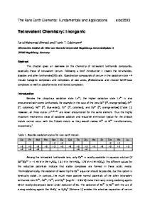
Fig. 3: Extreme Photonix’s BDEL small graphics prototype demonstrates the easy legibility of inorganic EL displays due to their high contrast. plans to sell the TFEL-display business sector of LiteArray, followed by a management buyout of that business to form ViewPoint Displays. • Toronto, Canada, April 2003. iFire Technology announced the Color-byBlue approach for EL technology, which led to the fabrication of a 600-cd/m2 prototype and could reduce capital requirements for manufacturing by 15%. • Baltimore, Maryland, May 2003. Extreme Photonix LLC demonstrated the first monochrome BDEL-display prototype with commercially viable luminance and pixel format and a reflectivity of less than 3%. Planar Systems described their move as part of a company-wide push to higher profitability by closing its U.S. manufacturing facilities – which produced significant numbers of custom TFEL products – and focusing on its line of more-profitable standard TFEL panels produced in Finland using an atomic-layer-epitaxy (ALE) process. During this same period, TDK Corp. resurfaced, after a fairly quiet R&D period, with a nearly product-ready fullcolor QVGA panel for automotive displays. The most impressive achievement of these turbulent 2 years is iFire’s 17-in. prototype TDEL panel, which now exhibits a maximum full-color luminance greater than 600 cd/m2 (Fig. 2). Such a luminance level was practically unimaginable in the mid-1990s, when much smaller full-color TFEL and TDEL displays could realize only 50 cd/m2 or so. In the aftermath of these developments, two conclusions are emerging: (1) monochrome TFEL technology remains viable and profitable and (2) the quest for significant expan-
sion of inorganic EL technology now depends on advances in variations of TDEL displays. Support for this argument could be found at the SID 2003 International Symposium held in Baltimore. For the first time in many years, not a single TFEL-technology paper was presented, nor a single product displayed; all of the papers and demonstrations on inorganic EL technology concerned the thick-dielectric type. The effect of thick dielectrics on the commercialization of EL technology has proven to be much more significant than the recent technical developments in other secondary display technologies, such as carbon nanotubes for field-emission displays (FEDs). Although efforts by ViewPoint Displays and other companies to increase the market share of TFEL displays through high-volume low-cost manufacturing are under way and may yet bear fruit, the fact remains that TFEL-technology R&D has diminished rapidly in just a few years, while TDEL approaches are attracting the majority of corporate R&D.
Meeting the Challenges In order to be successful in penetrating largescreen TV, automotive, or other lucrative high-volume markets, there are several challenges EL technology must overcome if it is to expand beyond the traditional niche markets served by monochrome TFEL panels (Table 1). The qualitative assessments in the table represent the full potential of TFEL, TDEL, and BDEL technologies based on present understanding. Sunlight-readable TFEL displays having a monochrome luminance of 50–300 cd/m2 and a low reflectivity of about 1% have long been commercialized. The luminous efficiency of
1–2 lm/W that has been achieved for ZnS:Mn phosphor used in TFEL panels is partly due to the high sensitivity of the eye to this phosphor’s yellow emission. The relative luminance penalty associated with red and blue phosphors, with efficiencies of less than 0.5 lm/W in TFEL displays, has prevented practical full-color products. Another challenge is that the TFEL dielectric capacitance – and, consequently, the power input coupled to the phosphor layer – is generally limited to less than 40 nF/cm2 because of the thickness requirement of thin-film dielectrics for high-voltage stability. Also, in TFEL devices, the dielectric/phosphor/dielectric stack must be free of high-field points, which in turn causes highly specular reflections and strong wave-guiding of the phosphorgenerated light. This limits the light outcoupling of high-contrast panels to just about 5%. In TDEL devices, on the other hand, the higher dielectric capacitance (up to hundreds of nF/cm2) and diffuse light-outcoupling (in the tens of percent) permit achievement of luminous efficiency approaching 10 lm/W for ZnS:Mn. The power consumption of inorganic EL panels, which is proportional to CV2, is dominated by parasitic capacitances
and only slightly increases with increasing dielectric capacitance. This and several other factors boost efficiency in TDEL and BDEL panels, including the ability to increase the thickness of the phosphor layer without an increase in operating voltage. TFEL and BDEL displays can be designed for superior dark contrast and an extremely steep luminance–voltage (L–V) slope. This is desirable for easy legibility (Fig. 3) and reduces much of the parasitic panel power consumption associated with modulation voltage. The very steep L–V slope necessary to achieve a modulation voltage less than 40 V requires that thin films be formed directly on smooth glass for a uniform electric field over the entire pixel area, which is necessary for simultaneous electrical breakdown of the phosphor layer. However, a more gradual L–V slope is required for ease of operation in gray-scale mode. The simplest way to achieve a gradual L–V slope is to use high- and low-field points to achieve varied electric-field distribution over the pixel area. However, a thick dielectric is generally required for this approach because high-field points cause “punch-through” of thin dielectrics, resulting in electrical shorts.
A gradual L–V slope is inherent in the TDEL device structure because of its non-planar thick/thin-film morphology, which can easily be implemented in a BDEL structure as well. A thick dielectric [Fig. 4(c)] provides tolerance to high-field points and other common thin-film defects (pinholes, particulates, scratches), which, in turn, results in strong manufacturing advantages over thin-film high-field EL technologies such as organic EL (OEL) technology [Fig. 4(a)] and TFEL technology [Fig. 4(b)]. This manufacturing advantage reduces capital-equipment investment for production, increases panel throughput and yield, and is one of the factors allowing inorganic EL technology to move closer to the production of affordable mass-marketable displays. Excellent dark-room contrast ratio is the starting point for high image fidelity and is easily achieved in all EL technologies. More difficult is maintaining that contrast in bright lighting conditions, which has long been a problem in plasma-display panels (PDPs) and cathode-ray tubes (CRTs) because they use diffusely reflecting powder phosphors. The thick dielectrics used in TDEL and BDEL devices are formed primarily from powder
Fig. 4: Surface or film irregularities can cause electrical shorts in OEL and TFEL pixel structures and dark-spot formation on OEL structures. These problems are avoided when thick/thin-film hybrid EL structures are used. Information Display 12/03
23
EL displays
formulations and produce a strong diffuse reflectivity as deposited. In TDEL devices, this problem can be solved. Extreme Photonix LLC has developed a black- or color-pigmentation method that turns a thick-film dielectric black (roughly 2–3% reflectivity), making TDEL displays legible at higher-ambient-light levels and in sunlight. The black thick dielectric separates BDEL displays from other thick-film displays by eliminating – and outperforming – external contrast-enhancement techniques such as neutral-density filters. Several promising variations of this blackor color-dielectric approach are discussed in the next section. One final issue is that of display reliability and lifetime. In general, inorganic EL technology is one of the most rugged technologies available, largely free from thermal sensitivity, shock, vibration, and other harsh-environment issues. And, with mono-
Fig. 5: (a) Shown is a high-contrast fullcolor EL-display structure using a blue phosphor, color-conversion media (CCM), and a blue filter. This sample structure of iFire Technology's Color-by-Blue approach includes an Extreme Photonix LLC blue dielectric for improved contrast. (b) Shown is the full mechanism for contrast enhancement and emission outcoupling. 24
Information Display 12/03
chrome displays exhibiting field-proven lifetimes exceeding 100,000 hours and full-color panels now exceeding lifetimes of 30,000 hours, EL technology has a clear lifetime advantage over other flat-panel emissive technologies such as PDP and OEL technologies.
The Future of Full-Color EL Displays To penetrate major display markets, inorganic EL displays clearly need a full-color technology that is competitive in both performance and cost of manufacturing. The conventional approach to efficient (minimum use of color filters) full-color integration is the sequential deposition and patterning of red-, green-, and blue-phosphor layers. An alternative approach is to use color-conversion media (CCM). Here, the output of a strong blue or violet/ultraviolet light source is absorbed in layers of fluorescent CCM materials, which then emit photons at longer wavelengths of light. This approach was first demonstrated with a luminance of a few cd/m2 by Y. Cho in 1997, using inorganic CCM layers and a UVemitting TFEL phosphor. Current full-color 17-in. iFire Technology panels use what the company calls its Color-by-Blue approach, in which a single blue-phosphor layer, red and green CCM, and a light-blue color filter are used to create the RGB subpixels (Fig. 5). These panels have a luminance of about 600 cd/m2 without neutral-density contrast enhancement and 200–300 cd/m2 with contrast enhancement. The CCM approach greatly simplifies fullcolor EL panels because it eliminates the need for patterning hydro-sensitive sulfide phosphors, allows a single phosphor anneal (different phosphors often require different annealing temperatures and durations), results in a single L–V slope characteristic and thereby simplifies column drivers for modulation of RGB subpixels, and alleviates differentialaging problems. The CCM approach would not be practical for inorganic EL displays if it were not for breakthroughs in the development of saturated blue EL phosphors in the late 1990s, the leading example of which is BaMgAlS:Eu (developed by Noboru Miura and his colleagues), which was recently reported to deliver a luminous efficiency exceeding 1 lm/W. The CCM approach is easily adaptable to inverted EL displays because organic CCM layers can be printed at the end of the fabrication process, which follows the high-temperature
annealing (550–750°C) of the EL phosphor. With quantum efficiencies of over 90%, CCM layers themselves can be very efficient, and can be made from simple combinations of inorganic powder phosphors or of organic fluorescent dyes in a PMMA (or other polymer) matrix. Despite the attractions of CCM, conventional color-integration approaches are still being pursued. For example, the most recent TDK Corp. 4.25-in. 240 × 180-pixel TDEL prototype uses a triple-patterned-phosphor process and produces bright displays at a power consumption of 10 W when displaying 100% white. The display produces 200 cd/m2 and exhibits a 3:1 contrast ratio in an ambient of 20,000 lux. There are several other possibilities for further increasing the luminance of full-color inorganic EL displays. One such concept, under development at Extreme Photonix LLC, uses existing black- and color-dielectric technology to boost the contrast-enhanced luminance of Color-by-Blue EL panels. This concept is incorporated in the structure shown in Fig. 5, and calls for the utilization of a highcontrast “blue” dielectric layer in a Color-byBlue EL panel. Preliminary results show a good blue reflective chromaticity of approximately x = 0.2 and y = 0.2 for high-capacitance blue thick dielectrics based on lead magnesium niobate and a blue-pigmentation dye compatible with the later patterning of CCM layers. The blue dielectric absorbs incident red and green ambient light without reducing the outcoupling efficiency of the blue-phosphor emission. Of course, approximately 50% of the red and green CCM emission is absorbed by the blue dielectric, so subpixel areas must be adjusted accordingly. Nonetheless, the theoretical improvement in luminance and contrast is significant. Assuming a panel white luminance of 1000 cd/m2 before contrast enhancement, 80% diffuse reflectivity from the rear thick dielectric, and the addition of a 40% neutral-density filter, the result is 13% diffuse luminous reflectivity and 400-cd/m2 luminance. By using a blue thick dielectric, a 9% luminous reflectivity and a luminance of 600 cd/m2 can be achieved. The most powerful embodiment would be a blue dielectric, with red and green color filters above the CCM, resulting in a reflectivity of about 2% and a luminance of 600 cd/m2 for a full-color contrast ratio of about 100:1 in a 1000-lux ambient, and 3:1 in a 50,000-lux ambient. This result would provide inorganic
EL displays with an advantage in very-highcontrast performance over PDPs.
Color-EL-Display Commercialization The prevalent model for monochrome TFEL production and sales is not applicable to the mass commercialization of inorganic color EL displays. Because of the extremely rugged specifications required by present TFELdisplay markets, product qualification adds a significant amount to the price tag for general consumers not requiring ruggedization. Resolution of this issue and several others is required for widespread acceptance of inorganic EL displays. Solutions for these problems exist conceptually. iFire Technology’s proposed price model for its 34-in. HDTV product is less than $2500 compared to the present cost of about $500 for a 5-in. monochrome TFEL graphics panel. Low manufacturing cost is essential, and this generally requires the development of color-EL-display manufacturing facilities in East Asia. Market entry fueled merely by costs lower than long-established technologies
is a tough sell, and EL technology will also have to convince investors and consumers that it offers higher performance than existing technologies. An additional momentum boost would be provided if difficulties in other emerging technologies, such as OEL technology, prove to be insurmountable.
as a leading candidate technology by major display powers. Time will tell if the hard-won technical breakthroughs translate into mass acceptance of inorganic EL displays. ■
At the Crossroads All the development and all the speculation support one clear conclusion: inorganic EL technology is at a crossroads. In the authors’ many discussions with those who know inorganic EL technology best – the longtime developers and users of the technology – the predictions of the future of EL technology can be split into two groups. The first group says that because of the late emergence of the majority of inorganic EL-technology breakthroughs it will be difficult for EL technology to make the leap, since it must now do so as an invasive technology. The second group says that inorganic EL technology is superior to existing technology in so many ways that it can no longer be ignored, and it should be pursued
SID ’04 Symposium, Seminar, and Exhibition
Seattle, Washington Washington State Convention and Trade Center May 23–28, 2004
Information Display 12/03
25