Structured P2P Networks in Mobile and Fixed Environments Jörg Eberspächer, Rüdiger Schollmeier, Stefan Zöls, Gerald Kunzmann Lehrstuhl für Kommunikationsnetze, Technische Universität München Arcisstr. 21, 80333 München, Germany, www.lkn.ei.tum.de {Joerg.Eberspaecher, Ruediger.Schollmeier, Stefan.Zoels, Gerald.Kunzmann}@tum.de
Abstract – Peer-to-Peer (P2P) networks and their applications gain increasing importance in today’s Internet, as already today the majority of IP traffic is caused by P2P applications. Since the upcoming of Napster a lot of research has been done in this area producing interesting and promising results. Still, growing demands like less data rate consumption, faster and more reliable search responses and the development of new applications engage many researchers worldwide. In this tutorial we therefore provide an overview about the area of P2P networking, its basic methods and a classification into unstructured and structured P2P networks. However the focus of this work is put on structured P2P networks, for which we explain in detail the most important routing algorithms. Based on this overview we can provide a discussion of the major advantages and disadvantages of the different P2P approaches, focusing especially on the applicability of P2P networks in heterogeneous environments. Index terms – Structured and Unstructured Peer-to-Peer, Distributed Hash tables, signaling efficiency, cross layer communication, heterogeneous networks.
I. INTRODUCTION Generally we can state that every P2P network establishes an overlay network, mostly based on TCP or on HTTP connections. Thus the overlay and the physical network can be separated completely from each other. The overlay connections thus do not reflect the physical connections, because of the abstraction layer of the TCP protocol stack, as indicated by Figure I-1.
Figure I-1 Schematic view of the physical and the virtual overlay network topology
T4/1
However by means of cross-layer communication the overlay network can be matched to the physical network if necessary. Such an adaptation is especially sensible if mobile networks are considered, as a significant reduction in the signaling traffic can be achieved (see section IV and [1-4]). The signaling traffic itself consists mainly of network maintenance and content requests and responses. In unstructured networks, network maintenance in this context means that the participants initiate in regular intervals keep-alive or neighborhood discovery messages to find the neighbors. Nodes receiving a neighborhood discovery message or a keep-alive request, reply with a keep-alive response. Thus every node knows at least a number of active participants in the overlay network, which are at least two hops in the overlay network away. To these nodes the node can connect if one of its direct neighbors fails. Further on, active peers issue in random intervals, determined by the user, content requests, to find the location of demanded content. As no knowledge about the topology of the network nor the location of the content is available in unstructured P2P networks, these requests have to be flooded through the network. In contrast in structured P2P networks these requests can be routed through the network (see section III). Responses, i.e. keep-alive responses or content responses are mainly routed through the network on the same path the fastest query was transferred through the network. Therefore every node stores the GUID of each request and the node where it received this response from for a certain time. Thus a P2P network can guarantee, that every response is routed on the shortest path in the overlay network regarding the transmission times. To be able to enter the virtual network, a new peer has to know at least one IP address of a node already participating in the overlay network. Otherwise a new node can not participate, as it is not able to establish any new connections in the overlay network. For the addresses of currently active nodes a new node may either rely on cached addresses of nodes which were active in a previous session or it may contact a bootstrap server. The bootstrap server is a well known host with a stable IP-address, which may itself participate in the overlay network, or which simply caches the IP addresses of nodes which used the bootstrap server to enter the network in a kind of FIFO memory. As nodes which just connected to the network are assumed to stay connected further on, the bootstrap server can thus provide IP addresses of active nodes with a high probability without actively participating in the overlay network. Other methods, like IP broadcasting or multicasting are hardly applicable, as they are mostly limited to small sub-networks. P2P networks are generally not used to transfer the content. The P2P network is only used for content lookup, i.e. to find out on which node a requested content is available. The transmission of the content is then done directly between the content provider and the requestor mostly via additional HTTP connections. HTTP is a standard data transmission protocol, which offers the possibility to transmit a file in several parts and from several sources in parallel or sequentially by using the content range header. Further on, using the overlay network only for signaling and to transfer the content out of band additionally reduces the load on the nodes participating in the overlay network, as they do not have to route the content. Only some P2P systems also transfer the content in the overlay e.g. to make the content source anonymous [5]. Further on, the problem of private IP realms, which can not be addressed from the outside, can be circumvented if the content is transferred within the overlay network. If no possibility to transfer the content inbound is available, at least the content provider or the requestor must have a public IP address, as the peer with the private IP address can address the public peer, but not vice versa. Thus if the node with private IP address provides the requested content, it also has to establish the connection to the requesting peer to transfer the content on this connection. Therefore Gnutella employs a PUSH message to signal the private IP address to transfer the requested content to the demanding peer, as no connection can be established from the public to the private peer. If both peers are located in private address realms this solution is not possible either. In this case the data can only be exchanged across the overlay, or via relays as described in [6]. As depicted by Table I-1 we distinguish throughout this work basically Client-Server and Peer-to-Peer systems. In Client-Server systems the server is the only provider of service or content, like e.g. a web server or a calendar server. The clients in this context only request content or a service as e.g. the contents of a web page or the set up of an appointment/meeting. Content in this context may be an mp3-compressed audio file, the profile of a person a user wants to establish a call to, or context information, like e.g. where the next taxi can be found. The clients do not provide any service or content, to run this system. Thus generally the clients are the lower performance systems and the server is the higher performance system. This does not exclude the fact that a server may be set up by a server farm, with one specified entry point for the clients, which may also redirect the clients e.g. for load balancing.
T4/2
In a Peer-to-Peer system, all available resources, i.e. the shared content and services, are provided by the peers. A peer in this context is simply an application running on a machine, which may be a common personal computer, a handheld or even a mobile phone. In contrast to a Client-Server network, we can generally not distinguish between a content requestor (client) and a content provider, as one application participating in the overlay in general offers content to other peers and requests content from other participants. This is best expressed by the expression "ServEnt", which is composed by the first syllable from the term Server and the second syllable of the term Client. Who provides what and which content is available where, is not managed by the network, as in P2P networks no central entity exists, which manages the content distribution. Only centralized Peer-to-Peer networks employ a central instance as a lookup table, or redirector, which responds to peer requests with a list of peers where the requested content is available. Therefore we categorize centralized P2P networks as unstructured P2P networks, as the overlay network and the content distribution are not managed. As depicted by Table I-1 we generally distinguish unstructured and structured P2P networks. In structured P2P networks the network topology and the location of content is determined by the employed P2P protocol. As content and the participating nodes share the same address space, any available object/peer can be reached in either case. In contrast to structured P2P networks, in unstructured P2P networks the random distribution of nodes and content may result in an undeterminable location of requested content. Thus the position of content can only be resolved in a local proximity of a node and only by flooding the request to a certain extent. However this alleviates unstructured P2P networks from the necessary signaling traffic to distribute the objects, or at least links to the shared objects, which is necessary in structured P2P networks.
Client-Server 1. Server is the central entity and only provider of service and content. Æ Network managed by the Server 2. Server as the higher performance system. 3. Clients as the lower performance system Example: WWW
Peer-to-Peer 1. Resources are shared between the peers 2. Resources can be accessed directly from other peers 3. Peer is provider and requestor (Servent concept)
Unstructured P2P
Structured P2P
Centralized P2P
Hybrid P2P
Pure P2P
DHT-Based
1. All features of Peerto-Peer included 2. Central entity is necessary to provide the service 3. Central entity is some kind of index/group database Example: Napster
1. All features of Peerto-Peer included 2. Any terminal entity can be removed without loss of functionality 3. Æ dynamic central entities Example: Gnutella 0.6, JXTA
1. All features of Peerto-Peer included 2. Any terminal entity can be removed without loss of functionality 3. Æ No central entities Examples: Gnutella 0.4, Freenet
1. All features of Peerto-Peer included 2. Any terminal entity can be removed without loss of functionality 3. Æ No central entities 4. Connections in the overlay are “fixed” Examples: Chord, CAN
Table I-1 Summary of the Characteristic Features of Client/Server and Peer-to-Peer networks
After this short introduction about the general characteristics of P2P networks, the remainder of this work is structured as follows. In section II we provide a short overview about unstructured P2P networks, which is followed in section III by a detailed description of the characteristics and the major protocols in the area of structured P2P networks. Based on this overview, we provide in section IV a short insight into problems and solutions when using P2P in heterogeneous networks. Section V finalizes this tutorial with a summary.
T4/3
II. UNSTRUCTURED P2P NETWORKS Generally we subdivide unstructured P2P networks, as depicted by Table I-1, into hybrid and pure P2P networks. They mainly differ in the routing behavior of queries and their search methods in the overlay network [7-10]. Hybrid P2P networks employ dynamic central entities, which establish a second routing hierarchy to optimize the routing behavior of flat overlay approaches. However in contrast to centralized P2P networks, any terminal entity can be removed from the network without any loss of the functionality of the overlay system. Pure P2P systems provide only one routing layer, and all nodes are equal, i.e. centralized instances are completely avoided in such a system. Despite to the bootstrap server, all connections in the overlay network are established randomly, as in general no further information is available to optimize the links in the overlay network. Further random behavior is added to the network because of the dynamics in P2P networks, as nodes frequently join and leave the overlay network, changing the topology permanently. Thus a meshed network establishes, with a large number of redundant paths and thus circles in the overlay. Due to the permanent change of the overlay network, unstructured P2P networks do not put any effort in the management or distribution of the shared content. Content added to the network by new joining nodes is also provided by these nodes, and can only be found on these nodes, as neither the content nor links, pointing to the offered content, are distributed in the network. Only in centralized and hybrid P2P networks, links providing information about the location of specific content is aggregated on a higher routing layer e.g. Superpeers or the Napster server. Thus in general requests have to be flooded in the network to reach nodes which can provide information where a specific content is available. Flooding in this context means that every incoming message is forwarded to all neighbors, except the neighbor in the overlay it received the message from. However some rules have to be established to prevent messages from being forwarded infinitely. Therefore a general message header is attached to every message, which includes a Time-to-Live (TTL) counter and a Global Unique Message ID (GUID). The Time-to-Live counter is decreased by every node which forwards a message, and as soon as the TTL counter reaches zero, the message is terminated without being forwarded any further. The same happens if a node receives a message with the same GUID twice within a certain time. The node terminates this message and does not forward it any further, as it must assume that it received this message twice due to a circle within the overlay network. Therefore, the second message must not be forwarded, as otherwise the message would circle infinitely. Circles within unstructured P2P networks can hardly be prevented, as not a single node has a complete overview about the network, and thus connections are established more or less randomly. Further on, the establishment of additional or new connections also depends on the connections a participant already has in the network. Due to the keep-alive algorithm, as described above, a node can only know nodes to which its neighbors are connected. If the bootstrap server is not well designed, e.g. as a LIFO, loops are established too, because a new node thus connects e.g. to the two nodes which connected beforehand it contacted the bootstrap server. As these two nodes are already connected to each other, a loop establishes as the new node connects to both nodes. That the overlay network structure is not determined by the protocol, is the main characteristic of unstructured P2P networks. Centralized P2P protocols certainly take a special role within unstructured P2P networks. In this case we can regard the centralized lookup server as the bootstrap server, to which the connection is never released. Thus one could also argue to categorize centralized P2P networks as structured P2P networks. However as the connections between the peers and the location of the content are not determined by an algorithm, centralized P2P networks do not fulfill the criteria to be classified as a structured P2P network. Napster [11] for example can be classified as a centralized P2P network, where a central entity is necessary to provide the service. In the Napster network a central database maintains an index of all files that are shared by the peers currently logged onto the Napster network. The database can be queried by all peers to lookup the IP addresses and ports of all peers sharing the requested file. In 2000 Napster offered the first P2P file-sharing application and with it a real P2P rush started. Today even more than 70% of the overall traffic in the German research network is caused by P2P applications [12]. The main disadvantage of a central architecture is its single point of failure. For this reason pure P2P networks like Gnutella 0.4 [13] have been developed. They are established and maintained completely without central entities. All peers in these overlay networks are homogeneous and provide the same functionality. Therefore, they are very fault resistant as any peer can be removed without loss of functionality. However, because of Gnutella’s unstructured network architecture, no guarantee can be given
T4/4
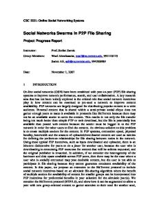
that content can be found. Besides, messages are coded in plain text and all queries have to be flooded through the network. This results in a significant signaling overhead and a comparable high network load [14-21]. Hybrid approaches, like Gnutella 0.6 [22] try to reduce network traffic by establishing a second routing hierarchy, i.e. the Superpeer layer [23]. By the differentiation of participating nodes in Superpeers and Leafnodes a significant reduction of the data rate consumption can be achieved, without loosing the network’s complete self organization. As we can observe from Figure II-1 which depicts a sub-part of the Gnutella 0.6 network measured in August 2002, the Superpeers among themselves are connected in a pure P2P way, while the Leafnodes use a Superpeer as a central entity. Thus Gnutella 0.6 can be classified as a hybrid unstructured P2P network. Other examples for unstructured P2P protocols and applications are AudioGalaxy (centralized) [24], eDonkey (hybrid) [25], FastTrack (hybrid) [26-29], JXTA (hybrid) [30], Freenet (pure) [31].
Figure II-1 Abstract network structure of a part of the Gnutella network (222 nodes measured on 2002-08-01)
Applying a geographical analysis on the Gnutella 0.6 network results in graphs shown in Figure II-2 and Figure II-3. Figure II-2 depicts the location of the Gnutella nodes from a measurement we took at the beginning of August 2002. Here we can clearly see that the majority of the nodes we reached during our measurements are located in Europe and in the USA. Only a few of them are located in other continents, like Australia or Africa. A reason therefore is, from our point of view, that most of the nodes are situated in bigger cities, and thus one dot in Figure II-2 can represent more than just one node.
Figure II-2 Location of the Gnutella nodes (3363 nodes until hop 7, measured on 2002-08-12)
T4/5
If we additionally visualize the overlay connections between the Gnutella nodes, the graph depicted by Figure II-3 results. The first astonishing result, which we can retrieve from this geographical analysis is the high number of connections established between P2P nodes located in Europe and P2P nodes located in the USA. This high number is represented by the broad black bar between Europe and the USA in Figure II-3. Applying a detailed analysis to the connectivity and location data, which is the basis for Figure II-3 reveals that more than 32% of all connections between Gnutella nodes are established between Europe and the USA. Additionally, we have to take into account that a significant number of connections from Europe to e.g. Australia or Asia are also routed via the USA. Thus this traffic is also transmitted across the Atlantic, although it is not shown in Figure II-3, because this figure only depicts the virtual connections of the overlay network and not the physical connections.
Figure II-3 Connections between the Gnutella nodes from Figure II-2 (2002-08-12)
Due to this inefficient connection establishment in the overlay, we propose in section IV methods to make P2P networks adapt itself automatically to the physical network during the runtime. Thus we can avoid zigzag routes, decrease the overall amount of signaling traffic significantly and decrease the average transmission delay. If we further on assume, as proved in [32], that close social groups have similar interests, and therefore geographically close groups have similar interests, we can thus additionally improve the performance of the network, as perceived by the user. The content is found faster, as the algorithm first searches for the content in a locally close proximity and additionally the content can also be downloaded faster, as the source and the sink are located closer to each other.
III. STRUCTURED P2P NETWORKS BASED ON DISTRIBUTED HASH TABLES A. Basic Concept Currently there exist a number of concepts which establish structured P2P networks. Chord [33], CAN [34] and PASTRY [35] are currently the most prominent P2P routing concepts which are based on distributed hash tables (DHT). The ID of each node and object may consist of several dimensions, i.e. several IDs for each object. An object in this context may be content or a description of content available in this network. Chord for example employs only one dimension, meaning that every node has to establish only one connection. Thus the nodes establish a ring structure. Content is described for example by the file name, keywords or other metadata. From these descriptions, hash values -so called keys- are calculated, using a hash function like SHA-1 [36]. Thus the nodes as well as the objects offered in this overlay are distributed in the same identifier space, which is illustrated by Figure III-1. Every node in such a network establishes a preconfigured number of TCP connections to nodes whose keys are the closest in any dimension. If a new node enters the network, it therefore first establishes a connection to a random node, which is already a member of the network, and is then redirected by the peer to those nodes which are the closest to the new node, concerning their key. Thus a certain number of connections must be reconfigured, to guarantee that every node is connected to its closest neighbors.
T4/6
node/peer-space
object-space
⊗
H()
identifier-space Figure III-1 Symbolic illustration of the distribution of peers and nodes by a hash function to the identifier space
The content brought into the network by every node is transferred to that active node whose key is the closest to the key of the object in any dimension, according to the used protocol. To further reduce the consumption of data rate, it is possible to transfer, instead of the content itself, a description of the content containing a link to the place where the content itself can be downloaded from. Thus any content can easily be found, as queries, containing hashed search keywords, must only be routed to that neighbor whose key is the closest to that of the search keywords. Resulting queries can be routed directly to those nodes, which are responsible for the content with the highest probability. An additionally benefit of structured P2P networks is that every query can be resolved, independent from the existence of the searched object in the network, as the location of the key of any object is predetermined by the used protocol. Thus flooding of query messages like in Gnutella 0.4 can be completely avoided, as requests can be routed directly to the node which is responsible for the key specified in the request. In the remainder of this section, we present four approaches for DHT-based P2P routing protocols, namely the CHORD protocol [33], the CAN protocol [34], Pastry [35] and Kademlia [37]. Furthermore a couple of other auspicious protocols exist, e.g., Tapestry [38], P-Grid [39], which are not described in further detail in this work. The basic routing approaches in these protocols are comparable to the routing approaches of the protocols described in this work. For further details we refer the reader to the above mentioned literature. B. CHORD CHORD is a structured peer-to-peer network protocol using a ring topology. The basic CHORD protocol is very simple and describes how nodes join the ring, how data is stored and how the ring recovers from node failures. Interfacing with applications, CHORD provides only one function: given a key, it maps the key onto a node. That node would typically be responsible for storing the data associated with that key, or it could store information about where that data can be found. In the following chapter, a short explanation of how the CHORD protocol works shall be given. 1) Consistent hashing A consistent hash function, such as SHA-1 [36], is used to generate an m-bit node identifier and an m-bit key-identifier. The node identifier is generated by hashing the node address (i.e. its port and IP address), while the key identifier is obtained by hashing the data that is supposed to be stored in the ring. The identifier length m should be chosen large enough to make the probability of hashing two node addresses or keys to the same value negligible. The node identifiers are arranged in a circle modulo 2m. This circle is called the CHORD ring. Every key k is assigned to the first node whose identifier n is equal to or larger than k. This node is called the successor node of key k. In a circular representation with identifiers increasing clockwise, keys are assigned to the first node that lies clockwise to them.
T4/7
Figure III-2 An identifier circle consisting of three nodes 0, 1 and 3. Key 6 is assigned to node 0, key 1 to node 1, and key 2 to node 3
Imagine a ring that consists of three nodes: 0, 1, and 3, and three keys: 1, 2 and 6, as shown in Figure III-2. Key 1 is assigned to node 1 as it is its responsible node. Key 2 is assigned to node 3, because node 2 does not exist and so node 3 is its successor. In the same way, key 6 is assigned to node 0. To maintain a consistent assignment of keys to nodes, certain keys have to be transferred to a newly entered node or from a leaving node. For example, if node 7 enters the ring, key 6 would have to be transferred from node 0 to node 7 as node 7 is now the successor of key 6. On the other hand, if node 1 leaves the ring, key 1 would have to be transferred to node 3. CHORD acts a distributed hash function. Using consistent functions will spread the keys evenly over the key space and therefore over the ring. All nodes receive roughly the same number of keys and so if a node joins or leaves the network, only an O(1/N) fraction of keys has to be moved to a different location. 2) Scalable key location Finding the node that maps to a key in the ring is very easy and needs almost no routing information. If every node knows its immediate successor node, queries can be routed throughout the ring by simply passing it from one node to the next node. If the query finally encounters a node n with n ≥ k, i.e. the node that succeeds key k, this is the node that the query maps to. However, resolving queries using this method is very inefficient, especially in large rings. In such a scenario, a query might require traversing the whole ring until it finally gets to the node that maps to the query. To accelerate queries, CHORD maintains additional routing information. This information is not required for correctness, which only depends on correct successor information. Let m be the number of identifier bits. Every node keeps a table of a maximum of m entries, called the finger table (Figure III-3). Each entry of index i points to the node s that succeeds n by at least 2i-1 on the identifier circle, i.e. s = successor(n + 2i-1). This node s is called the ith finger of node n. Note that the first finger of n is always its immediate successor. There are two important characteristics of the finger table: • Each node n has to keep information about only m other nodes in the ring. It knows more about nodes closely following it on the identifier circle than nodes farther away. • A node n usually does not have enough information about other nodes to directly determine the successor of a given key k
T4/8
Figure III-3 Finger tables and key locations for a ring with nodes 0, 1, and 3, and keys 1, 2 and 6. Fingers for node 0 are shown
Now, a node n looking for the successor of key k can use these "shortcuts" through the ring to determine the key's immediate predecessor. This node's successor is also the successor of k. To do this, n searches its finger table for a node j that most immediately precedes k. It will then ask j for the node it knows who is closest to k. By repeating this process, n learns about nodes closer and closer to k. This is called iterative routing (Figure III-4). Using this look-up mechanism, in a fully-intact ring, queries will take O(log N) hops to complete. Given this, one can see that CHORD scales very well with an increasing number of participating nodes N.
Figure III-4 Iterative routing
3) Stabilization As we have seen before, keeping successor pointers up to date is sufficient to guarantee correctness of lookups. These successor pointers are used to verify and correct finger tables, which allow lookups to be fast and correct. A stabilization scheme guarantees adding nodes to the CHORD ring while maintaining reach ability of existing nodes. This must be true even if there is a lot of nodes concurrently joining and leaving. By itself, stabilization will not repair a CHORD ring that has split to one or more disjoint cycles or cycles that wrap around the identifier space multiple times. These pathological cases are not discussed in this paper.
T4/9
Stabilize is run periodically on every node and aims at correcting wrong successor and predecessor entries, that occur due to joining and leaving nodes. When n runs stabilize, it asks its successor s for s's predecessor p. In most cases, this is node n. If a node recently joined the network and its ID is situated between n and n’s successor, then node n has to update its successor entry. Besides, its old successor is notified about the change and will update its predecessor pointer now. If p is located between n and s, p is a node that has recently joined, so n will now acquire p as its new successor. Finally, stabilize notifies n's successor of n's existence, so that its new successor p can change its predecessor to n. Although stabilization fixes successor pointers quite quickly, a lookup can occur before all pointers have been updated. We then can distinguish between three cases. The common case is that the change in the topology did not affect the lookup procedure, so the correct successor is found in O(log N) steps. If successor pointers are correct, but fingers are inaccurate, lookups yield correct results, but they may be slower. In the final case, the nodes in the affected region have incorrect successor pointers, or key have not yet been forwarded to newly joined nodes, and the lookup may fail. The higher-level software using CHORD has the option to retry the lookup after a short pause. On start-up, a joining node n contacts an arbitrary known CHORD node n' and ask n' to find its immediate successor s. This does not make the ring aware of n, but the periodic stabilize algorithm will fix successor pointers quickly. Suppose node n joins the system and its ID lies between nodes np and ns (Figure III-5). Using the join function, n knows of ns as its successor. n would now acquire ns as its successor. Node ns, when notified by n, would acquire n as its predecessor. When np next runs stabilize, it will ask ns for its predecessor (which is now n); np would then acquire n as its successor. Finally, np will notify n and n will acquire np as its predecessor. At this point, all predecessor and successor pointers are correct and the newly joined node is now part of the system and lookups will work.
Figure III-5 How nodes join the CHORD ring
The last operation that has to be performed when a node n joins the network is to move the keys, that n is now responsible for, from the neighbouring node to node n. As it can become the successor only for keys that were previously in the responsibility of the node immediately following n, it only needs to contact that one node to transfer the relevant keys.
T4/10
4) Failures and replication When a node n fails (i.e. power break, network problems, ...), all nodes whose finger tables include n must find n's successor. Furthermore, the failure of n must not disrupt queries that are in progress as the system is re-stabilizing. As pointed out above, the most important thing in a CHORD ring is to keep successor pointers correct. To do this, every node keeps a list of its r nearest successors on the ring. The stabilize routine would normally keep this list. r should be of O(log N). If node n notices that its successor s has failed, it discards s from its list of successors and tries to stabilize with the next live entry in the successor list, s'. At that point, n can direct lookups for keys for which the failed node s was the successor to the new successor s'. After a node has failed, it takes quite some time until all finger table entries and successor lists are corrected by the stabilize procedure. During this time, other nodes may try to send requests to or through the failed node. With the failed node not responding, after a time-out, another path can be chosen in most cases. This can be done for instance by using the finger table entry that precedes the failed node in the sending node's finger table. Nodes in the successor list may also be an alternative if the failed node is close to the sending node. But what happens to the keys that were associated to the failed node n? In many cases, we can assume that n did not have time to hand these keys over to its successor, so this data is lost. To address this problem, higher-level software can use the successor list. With stabilize automatically maintaining this list, replicas of the keys could be stored at succeeding nodes. Doing so, this data won't be lost if n failed, because its successor can now answer the query instead of n. The CHORD software can be used to inform higher-level software of successors coming and leaving and so enable this software to implement a replication system. CHORD is fully distributed, with no node being more important than another. In case of node failures, the system will still be intact and able to respond to queries. Even in a continuously changing system, CHORD will be able to find the node responsible for a key in a defined number of hops. Enhancements of the Chord protocol are presented in [37, 40-49]. C. CAN The term “CAN“ stands for “Content-Addressable Network”. It is, like CHORD, a P2P protocol based on the concept of DHTs. The main feature of CAN is the mapping of a key k onto a point P in a ddimensional Cartesian coordinate space. The coordinate space is partitioned among all nodes in the CAN so that each node is responsible for a zone. Figure III-6 shows a 2-dimensional 2-bit coordinate space partitioned between 5 CAN nodes. 00
01
10
11
11 Zone of node A
Zone of node B
(00-01, 10-11)
(10-11, 10-11)
10 y
Zone of node D Zone of node C
(10-11, 01)
01
(00-01, 00-01)
Zone of node E (10-11, 00)
00
x
Figure III-6 A 2-dimensional 2-bit coordinate space in CAN with 5 nodes
T4/11
To store a key k on the appropriate node, a d-dimensional hash function is used to map k onto the corresponding point P in the coordinate space. The key k is stored at that node in whose zone P lies. Each node maintains a routing table that holds all neighbors of the node. To route a query towards its destination, a node forwards it to its neighbor with coordinates closest to the query’s destination coordinates. For example, node D in Figure III-6 keeps nodes B, C and E in its routing table. A query for key (01, 11) is routed from node D to node B and onward to node A, which is the responsible node for this key. In case that one or more of a node’s neighbors fail, a query would be forwarded simply to the next best available neighbor. Even if all neighbors that are closer to the destination fail, a node can locate a node closer to the destination by means of an expanding ring search (stateless, controlled flooding over the unicast CAN overlay mesh). As shown in [34], the average routing path length in a CAN is (d/4)·(N1/d), where N is the total number of nodes in the CAN, and the number of neighbors an individual node must maintain is 2·d. Thus the number of nodes (and hence zones) in the network can grow without an increasing per-node-state, while the path length grows with O(n1/d). When a new node joins the CAN, it randomly chooses a point P in the coordinate space and sends a JOIN request for P to any known node in the network. The JOIN request is routed to that node in which zone P is located. This node splits its zone in two equal-sized parts and assigns one half (including all keys of that half zone) to the new node. The new node learns its coordinate neighbors from the previous occupant of its zone. Finally, all neighbors are notified to update their neighbor sets. Figure III-7 depicts the join procedure of a new node. A node leaving the CAN must hand over its zone (including all keys) to one of its neighbors. So either a valid single zone is produced (if zones can be merged) or the remaining node must handle both zones. In this case the neighbor with the smallest zone is chosen.
A
B
C
A
B
C
{B, D}
{A, C, D}
{B, E}
{B, D}
{A, C, N}
{B, E}
D {A, B, E}
PN
E
D
N
E
{C, D}
{A, N}
{B, D, E}
{C, N}
X {Y, Z}
Node owning the zone Neighboring nodes
Figure III-7 Example 2-dimensional coordinate space before and after node N joins the CAN
To be capable to deal with node failures, update messages are periodically sent to each neighbor of a node. Thus the failure of a neighboring node can be detected by a prolonged absence of an update message. Once a node decides that one of its neighbors has failed, it starts a takeover timer initialized in proportion to the volume of the node’s zone volume. This is done by all neighboring nodes that detect the failure. Finally, the failed node’s zone is taken over by that node which timer expires first. This timer mechanism ensures that the neighboring node with the smallest zone volume takes over the zone of the failed node. The common leaving procedure and the takeover algorithm can both result in nodes being responsible for multiple zones. In [34] the so-called background zone-reassignment algorithm is proposed that prevents further fragmentation of the coordinate space and makes the CAN tend back towards only one zone per node. The CAN protocol offers a variety of design improvements to reduce the latency of routing -which can be achieved by either reducing the path length (e.g. the average number of CAN hops) or the per-hop latency- and to add load balancing mechanisms. The following list gives a short introduction into these mechanisms. We refer the interested reader to [34] for a detailed description. 1. In CAN, the dimensionality of the coordinate space can be chosen arbitrarily. Increasing the dimensions of the coordinate space leads to a reduced number of CAN hops and therefore to a reduced routing latency. When the dimensionality increases, every node in the network has more neighbors, thus also the routing fault tolerance improves as a node has more potential next hop nodes to route a message towards its destination. A drawback is that the number of neighbors a CAN node must maintain is 2·d, so the per-node-state is increasing arithmetically with the dimensionality.
T4/12
2. Another possibility to reduce the average number of hops is the use of multiple coordinate spaces, socalled “realities”. Every node in the CAN is assigned to r zones, one on every reality, and therefore must maintain a neighbor set for every reality. Although this approach increases the per-node-state arithmetically with the number of realities, three great improvements of the CAN results from it: First, each pair is replicated on every reality, which leads to an improved data availability. Second, an improved routing fault tolerance results, because in case of a routing breakdown on one reality, the message can be routed via one of the remaining realities. Last but not least, using multiple realities greatly reduces the average path length, because a node forwards a message to that neighboring node on the reality with coordinates closest to the destination. 3. A possibility to decrease the per-hop-latency in a CAN is to measure the network-level round-trip-time (RTT) to each neighbor to better reflect the underlying IP topology of the network. When routing a message towards its destination, a node forwards the message to that neighbor with the maximum ratio of progress (i.e. how much the Cartesian distance towards the destination is decreased) compared to the RTT. A high number of dimensions, as explained above, still improves this concept as more nexthop choices are available. 4. The overloading of coordinate zones is another mechanism that offers some improvements to a CAN. Overloading a zone means that multiple nodes share one zone. By means of zone overloading the average routing path length decreases, because assigning one zone to multiple nodes has the same effect as reducing the total number of nodes in the system. As we stated above, the path length in a CAN grows as O(1/d). However, not only the path length but also the per-hop latency can be decreased. This can be done by measuring the RTT to every node in a neighboring zone and by forwarding a message to that node with the lowest RTT. Another advantage is the improved fault tolerance, because a zone is vacant only in case that all nodes of this zone fail. Negative aspects of zone overloading are the increasing per-node-state (every node must maintain a list with all other nodes in its zone), the network traffic generated by the RTT measurement and the increasing volume of the zones. 5. In case of using h different hash functions, a key k is mapped onto h points in the coordinate space. From this replication an improved data availability results, because a pair is available as long as only one of the h responsible nodes is available. In addition, a query will be accelerated if a node routes it to that responsible node with coordinates closest to its own. On the other hand, every node has to bear h times the number of keys it would have to bear when only a single hash function is used. A major problem of all structured P2P networks is the incongruence of the overlay network structure with the underlying IP topology. This can lead to inefficient routing scenarios, as depicted in Figure III-8. The CAN nodes A and C are located in Europe, while node B is located in the United States. Node B is the right neighbor of A and the left neighbor of C. A query routed from A to C therefore has to cross twice the distance between the two continents. An approach to adapt the CAN overlay structure to the underlying IP topology can be made as follows. A set of m well-known computers, e.g. DNS servers, act as landmarks on the Internet. Every CAN node in the network measures the RTT to each of these landmarks and sorts them in ascending order. With m landmarks, m! such orderings are possible. Accordingly the coordinate space is partitioned into m! equal sized portions, and each portion is corresponding to one possible ordering. When a new node joins the CAN chooses a random point in that portion of the coordinate space that is associated with its landmark ordering. As topologically close nodes have the same landmark ordering, they are located in the same portion of the coordinate space. Thus the neighbors of a node in the CAN overlay structure are likely to be topologically close on the underlying IP layer. This topologicallysensitive construction of the CAN overlay network can greatly improve the path latency, but on the other hand the coordinate space is not longer uniformly populated of course.
T4/13
A
B
C A
routing
C
B
Figure III-8 Inefficient routing in a CAN
6. All improvements of the CAN design mentioned above mainly aim at reducing the routing latency. Another possibility to improve the performance of a CAN is to add load balancing mechanisms which take care that all participating nodes have nearly the same number of pairs to store. Therefore, every node knows not only its own zone volume, but also the zone volume of all its neighbors. When a node receives a JOIN message, it compares the volume of its own zone with those of its neighbors and chooses the zone with the largest volume to be split whereas one half is assigned to the new node. As the volume of a zone is indicative of the number of assigned pairs, a uniform partitioning of the coordinate space is one possibility to achieve load balancing in a CAN. 7. Other load balancing mechanisms are the use of caching and replication techniques. As shown in [50], some pairs in a CAN are much more frequent than others, so the responsible nodes for these pairs have to bear a lot of data and must reply to a large number of queries. If every CAN node maintains a cache of data keys it recently accessed, it is able to directly reply to a query for such a key without forwarding the query any further. The replication of keys on neighboring nodes is a possibility for overloaded nodes to reduce the number of requests they have to handle. With this concept, some or all neighbors of the original storage node are able to reply to a query, and thus the number of queries the original storage node must reply to decreases. D. Pastry Pastry [35] follows two goals with its DHT based overlay routing approach. Firstly, just like in Chord, Pastry provides methods to be able to route to any shared object available and identifiable with a genuine key in the overlay network. Secondly, Pastry takes into account network locality. Thus Pastry minimizes the distance the message travels, according to a scalar metric, like the geographical distance, the distance within the IP network in terms of hops or delay. Like in Chord, in Pastry every node and every object is described uniquely by its node-ID or key, which is set up as 128 bit identifier. This identifier is for example computed as the SHA-1 [36] key from the MAC or IP address of a participating node or from the keyword describing a shared object in the Pastry overlay. Thus nodes and objects are hashed to the same identifier space, providing the ability to route to content objects as well as to nodes. Additionally, to minimize the routing distance, every link between two nodes is described by the distance between the two nodes, according to the scalar metric defined in the respective Pastry system. However these descriptions have to be computed always between two nodes establishing a connection or at least knowing about each other. The descriptions are only valid for every single connection, and therefore are determined locally on every single participating node. The Pastry system is in general characterized by two parameters, namely the base b and the length l of the IDs employed in Pastry. The parameter b determines the base 2b for the notation of the IDs and l determines the number of digits of every ID, which thus also determines the size of the ID space. The value range of l is determined thus by the following equation: 128 (1) 0≤l