On Cooperative Caching in Wireless P2P Networks ∗ Jing Zhao, Ping Zhang and Guohong Cao Department of Computer Science and Engineering Pennsylvania State University E-mail: {jizhao,pizhang,gcao}@cse.psu.edu Abstract Some recent studies have shown that cooperative cache can improve the system performance in wireless P2P networks such as ad hoc networks and mesh networks. However, all these studies are at a very high level, leaving many design and implementation issues unanswered. In this paper, we present our design and implementation of cooperative cache in wireless P2P networks. We propose a novel asymmetric cooperative cache approach, where the data requests are transmitted to the cache layer on every node, but the data replies are only transmitted to the cache layer at the intermediate nodes that need to cache the data. This solution not only reduces the overhead of copying data between the user space and the kernel space, it also allows data pipelines to reduce the end-to-end delay. We also study the effects of different MAC layers such as 802.11 based ad hoc networks and multi-interface multi-channel based mesh networks, on the performance of cooperative cache. Our results show that the asymmetric approach outperforms the symmetric approach in traditional 802.11 based ad hoc networks by removing most of the processing overhead. In mesh networks, the asymmetric approach can significantly reduce the data access delay compared to the symmetric approach due to data pipelines.
1. Introduction Wireless P2P networks such as ad hoc network, mesh networks, and sensor networks, have received considerable attention due to their potential applications in civilian and military environments. For example, in a battlefield, a wireless P2P network may consist of several commanding officers and a group of soldiers. Each officer has a relatively powerful data center, and the soldiers need to access the data centers to get various data such as the detailed geographic information, enemy information, and new commands. The neighboring soldiers tend to have similar missions and thus ∗ This work was supported in part by the National Science Foundation under grant CNS-0721479.
share common interests. If one soldier has accessed a data item from the data center, it is quite possible that nearby soldiers access the same data some time later. It will save a large amount of battery power, bandwidth, and time if later accesses to the same data are served by the nearby soldier who has the data instead of the faraway data center. As another example, people in the same residential area may access the Internet through a wireless P2P network, e.g., the Roofnet [2]. After one node downloads a MP3 audio or video file, other people can get the file from this node instead of the far away web server. Through these examples, we can see that if nodes are able to collaborate with each other, bandwidth and power can be saved, and delay can be reduced. Actually, cooperative caching [4, 14, 21, 22], which allows the sharing and coordination of cached data among multiple nodes, has been applied to improve the system performance in wireless P2P networks. However, these techniques [4, 14, 21, 22] are only evaluated by simulations and studied at a very high level, leaving many design and implementation issues unanswered. There have been several implementations of wireless ad hoc routing protocols. In [20], Royer and Perkins suggested modifications to the existing kernel code to implement AODV. By extending ARP, Desilva and Das [6] presented another kernel implementation of AODV. Dynamic Source Routing (DSR) [10] has been implemented by the Monarch project in FreeBSD. This implementation is entirely in-kernel and does extensive modifications in the kernel IP stack. In [1], Barr et al. addressed issues on systemlevel support for ad hoc routing protocols. In [11], the authors explored several system issues regarding the design and implementation of routing protocols for ad-hoc networks. They found that the current operating system was insufficient for supporting on-demand or reactive routing protocols, and presented a generic API to augment the current routing architecture. However, none of them has looked into cooperative caching in wireless P2P networks. Although cooperative cache has been implemented by many researchers [5, 8], these implementations are in the Web environment, and all these implementations are at the
system level. As a result, none of them deals with the multiple hop routing problem, and can not address the ondemand nature of the ad hoc routing protocols. To realize the benefit of cooperative cache, intermediate nodes along the routing path need to check every passing-by packet to see if the cached data match the data request. This certainly cannot be satisfied by the existing ad hoc routing protocols. In this paper, we present our design and implementation of cooperative cache in wireless P2P networks. Through real implementations, we identify important design issues and propose an asymmetric approach to reduce the overhead of copying data between the user space and the kernel space, and hence reduce the data processing delay. Another major contribution of this paper is to identify and address the effects of data pipeline and MAC layer interference on the performance of caching. Although some researchers have addressed the effects of MAC layer interference on the performance of TCP [9] and network capacity [15], this is the first work to study this problem in the context of cache management. We study the effects of different MAC layers such as 802.11 based ad hoc networks and multi-interface multi-channel based mesh networks, on the performance of caching. Our results show that the asymmetric approach outperforms the symmetric approach in traditional 802.11 based ad hoc networks by removing most of the processing overhead. In mesh networks, the asymmetric approach can significantly reduce the data access delay compared to the symmetric approach due to data pipelines. The rest of the paper is organized as follows. Section 2 presents our design and implementation of cooperative cache for wireless P2P networks. In Section 3, we present our prototype and experimental results. Section 4 extends our cooperative cache design to a large scale network and presents extensive simulation results based on various MAC layers. Section 5 concludes the paper.
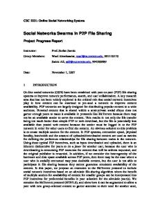
2. Design and Implementation of Cooperative Caching In this section, we first present the basic ideas of the three cooperative caching schemes proposed in [22]: CachePath, CacheData, and HybridCache. Then, we discuss some design issues, and present our design and implementation of cooperative cache in wireless P2P networks. N9
N0
N10 N8 N5 N3 N4 N6
N7
N2
Figure 1. A wireless P2P network
N1
2.1. Cooperative Caching Schemes Figure 1 illustrates the CachePath concept. Suppose node N1 requests a data item di from N0 . When N3 forwards di to N1 , N3 knows that N1 has a copy of the data. Later, if N2 requests di , N3 knows that the data source N0 is three hops away whereas N1 is only one hop away. Thus, N3 forwards the request to N1 instead of N4 . Many routing algorithms (such as AODV [18] and DSR [10]) provide the hop count information between the source and destination. Caching the data path for each data item reduces bandwidth and power because nodes can obtain the data using fewer hops. However, mapping data items and caching nodes increases routing overhead, and the following techniques are used to improve CachePath’s performance. In CachePath, a node need not record the path information of all passing data. Rather, it only records the data path when it is closer to the caching node than the data source. For example, when N0 forwards di to the destination node N1 along the path N5 −N4 −N3 , N4 and N5 won’t cache di path information because they are closer to the data source than the caching node N1 . In general, a node caches the data path only when the caching node is very close. The closeness can be defined as a function of the node’s distance to the data source, its distance to the caching node, route stability, and the data update rate. Intuitively, if the network is relatively stable, the data update rate is low, and its distance to the caching node is much shorter than its distance to the data source, the routing node should cache the data path. In CacheData, the intermediate node caches the data instead of the path when it finds that the data item is frequently accessed. For example, in Figure 1, if both N6 and N7 request di through N5 , N5 might think that di is popular and cache it locally. N5 can then serve N4 ’s future requests directly. Because the CacheData approach needs extra space to save the data, it should be used prudently. Suppose N3 forwards several requests for di to N0 . The nodes along the path N3 , N4 , and N5 might want to cache di as a frequently accessed item. However, they will waste a large amount of cache space if they all cache di . To avoid this, CacheData enforces another rule: A node does not cache the data if all requests for the data are from the same node. In this example, all the requests N5 received were from N4 , and those requests in turn came from N3 . With the new rule, N4 and N5 won’t cache di . If N3 receives requests from different nodes, for example, N1 and N2 , it caches the data. Certainly, if N5 later receives requests for di from N6 and N7 , it can also cache the data. CachePath and CacheData can significantly improve system performance. Analytical results [22] showed that CachePath performs better when the cache is small or the data update rate is low, while CacheData performs better in other situations. To further improve performance, we can use HybridCache, a hybrid scheme that exploits the
strengths of CacheData and CachePath while avoiding their weaknesses. Specifically, when a node forwards a data item, it caches the data or path based on several criteria discussed in [22].
2.2. Design Issues on Implementing Cooperative Cache To realize the benefit of cooperative cache, intermediate nodes along the routing path need to check every passingby packet to see if the cached data matches the data request. This certainly cannot be satisfied by the existing ad hoc routing protocols. Next, we look at two design options. 2.2.1 Integrated Design In this option, the cooperative cache functionalities are integrated into the network layer, so that the intermediate node can check each passing by packet to see if the requested data can be served. Although this design sounds straightforward, several major drawbacks make it impossible in real implementation. The network layer is usually implemented in kernel, and hence, the integrated design implies a kernel implementation of cooperative cache. However, it is well known kernel implementation is difficult to customize and then it is difficult for handling different application requirements. Secondly, kernel implementation will significantly increase the memory demand due to the use of CacheData. Finally, there is no de facto routing protocol for wireless P2P networks currently. Implementing cooperative cache at the network layer requires these cache and routing modules to be tightly coupled, and the routing module has to be modified to add caching functionalities. However, to integrate cooperative cache with different routing protocols will involve tremendous amount of work. 2.2.2 Layered Design The above discussions suggest that a feasible design should have a dedicated cooperative cache layer resided in the user space; i.e., cooperative cache is designed as a middleware lying right below the application layer and on top of the network layer (including the transport layer). There are two options for the layered design. One naive solution uses cross-layer information, where the application passes data request (search key) to the routing layer, which can be used to match the local cached data. However, this solution not only violates the layered design, but also adds significant complexity to the routing protocol which now needs to maintain a local cache table. Further, if an intermediate node needs to cache the data based on the cooperative cache protocol, it has to deal with fragmentation issues since some fragments of the data may not go through this node. Thus, this naive solution does not work in practice. Another solution is to strictly follow the layered approach, where the cooperative cache layer is on top of the
Request
CCache
CCache
CCache
CCache
CCache
CCache
Network and Transport
Network and Transport
Network and Transport
Network and Transport
Network and Transport
Network and Transport
N0 (Data Center)
N1
N2
N3
N4
N5 (Client)
(a) The request packet flow Reply
CCache
CCache
CCache
CCache
CCache
CCache
Network and Transport
Network and Transport
Network and Transport
Network and Transport
Network and Transport
Network and Transport
N0 (Data Center)
N1
N2
N3
N4
N5 (Client)
(b) The reply packet flow
Figure 2. Layered design network layer (TCP/IP). Figure 2 shows the message flow in dashed line in the layered design. As shown in the figure, suppose N5 sends a request to N0 . Based on the routing protocol, it knows that the next hop is N4 and sends the request to N4 encapsulating the original request message. After N4 receives the request, it passes the message to the cache layer which can check if the request can be served locally. This process continues until the request is served or reaches N0 . After N0 receives the request, it forwards the data back to N5 hop by hop, which is the reverse of the data request, as shown in Figure 2 (b). Note that the data have to go up to the cache layer in case some intermediate nodes need to cache the data. Although this solution can solve the problems of the naive solution, it has significant overhead. For example, to avoid caching corrupted data, reliable protocols such as TCP are needed. However, this will significantly increase the overhead, since the data have to move to the TCP layer at each hop. Note that the data only need to go to the routing layer if cooperative cache is not used. Further, this solution has a very high context switching overhead. At each intermediate node, the packet has to be copied from kernel to user space for cache operations, and then re-injected back to kernel to be routed to the next hop. The pipeline effect: Another problem of the layered design is the lack of data pipeline. Normally, the transport layer can fragment a large data packet into many small data packets, which are sent one by one to the next hop. If there are multi-hops between the sender and the receiver, these small packets can be pipelined and the end-to-end delay can be reduced. In cooperative cache, the caching granularity is at the data item level. Although a large data item is still fragmented by the transport layer, there is no pipeline due to the layered design. This is because the cache layer is on top of the transport layer, which will reassemble the fragmented
packets. Since all packets have to go up to the cache layer hop by hop, the network runs like “stop and wait” instead of “sliding window”. This will significantly increase the end-to-end delay, especially for data with large size.
2.3. The Asymmetric Cooperative Cache Approach To address the problem of the layered design, we propose an asymmetric approach. We first give the basic idea and then present the details of the scheme. 2.3.1 The Basic Idea In our solution, data requests and data replies are treated differently. The request message still follows the path shown in Figure 2 (a); however, the reply message follows a different path. If no intermediate node needs to cache the data, N0 sends the data directly to N5 without going up to the cache layer. Suppose N3 needs to cache the data based on the cooperative cache protocol, as shown in Figure 3. After N3 receives the request message, it modifies the message and notifies N0 that the data should be sent to N3 . As a result, the data are sent from N0 (or other intermediate node which needs to cache the data) to N3 through the cache layer, and then sent to N5 . Note that the data will not go to the cache layer in intermediate nodes such as N1 , N2 , and N4 in this example. In this way, the data only reach the routing layer for most intermediate nodes, and go up to the cache layer when the intermediate node needs to cache the data. Although the request message needs to go up to the cache layer, it has a small size, and the added overhead should be limited. Reply
CCache
CCache
CCache
CCache
CCache
CCache
Network and Transport
Network and Transport
Network and Transport
Network and Transport
Network and Transport
Network and Transport
N1
N2
N3
N4
N0 (Data Center)
N5 (Client)
Figure 3. In the asymmetric approach, the data reply only goes up to the cache layer at the intermediate nodes that need to cache the data. If the requested data item is large, this Asymmetric approach allows data pipeline between two caching nodes, and hence reduces the end-to-end delay. The cache layer processing overhead, especially data copying between kernel and user space, is also minimized because the data item will not be delivered to the cache layer at nodes that are unlikely to cache the data. Next, we discuss the details of our asymmetric approach. 2.3.2 The Asymmetric Approach Our asymmetric caching approach has three phases.
Phase 1: Forwarding the Request Message: After a request message is generated by the application, it is passed down to the cache layer. To send the request message to the next hop, the cache layer wraps the original request message with a new destination address which is the next hop to reach the data server (real destination). Here, we assume that the cache layer can access the routing table and find out the next hop to reach the data center. This can be easily accomplished if the routing protocol is based on DSR or AODV. In this way, the packet is received and processed hop by hop by all nodes on the path from the requester to the data server. For example, in Figure 2 (a), when N5 requests di from N0 , it adds a new header where the destination of the data request becomes N4 , although the real destination should be N0 . After N4 receives and processes the packet, it changes the destination to be N3 , and so on, until the request packet arrives at N1 . When an intermediate node receives the request message and delivers to the cache layer, the cache manager performs two tasks: First, it checks if it has the requested data in its local cache; if not, it then checks whether to cache the requested data based on the decision formula suggested in [22]. The decision considers its local statistics such as the access ratio of this data item, distance to the data center and route stability. If it decides to cache the requested data, its node id will be added to Cache List, which is a linked list encapsulated in the cache layer head. When the request message reaches the node who has the data, Cache List in the message will include all the intermediate nodes along the forwarding path which want to cache the requested data. Phase 2: Determining the Caching Nodes: When a request message reaches the data server (the real data center or the intermediate node that has cached the requested data), the cache manager examines the Cache List, and makes the final judgment on which ones in the Cache List will cache the data; it may remove some nodes if necessary. One advantage of letting the data server revise the caching decision is that the data server can use more parameters to refine the relevance of caching. For example, the data center can add update ratio as another parameter and re-evaluate the caching decision. If many intermediate nodes decide to cache the data based on the formula provided in [22], the data server can compare the relevance of each node, and select those with highest relevance into Cache List, to avoid generating too much unnecessary cache data. Also, if the geographic location or hop distance of the intermediate node in Cache List is attached, the data server can better determine the distribution of the caching nodes, e.g. to avoid too many data replicas in one area. Phase 3: Forwarding the Data Reply: Unlike the data request, the data reply only needs to be processed by those nodes that need to cache the data. To deliver the data only to
those that will cache the data, tunneling techniques [7] are used. The data reply is encapsulated by the cache manager, and tunneled only to those nodes appeared in Cache List. As shown in Figure 3, suppose the intermediate node N3 needs to cache data di . Then, N3 and N5 are the nodes to process the data at the cache layer. N0 includes N3 and N5 in the cache header of the data item di , and first sets the destination address of di to be N3 . When N3 receives any fragmented packet of di , the routing layer of N3 will deliver the packet upward to transport layer and then to the cache layer. After the whole data item di has been received by N3 , it caches the data item, sets the next destination using the next entry in Cache List, which is N5 , and then passes the data down to the routing layer. After N5 receives the data, it delivers it to the application layer.
2.4. System Implementation The cooperative cache middleware sits below the application layer and above the network layer. It consists of three parts: Cooperative Cache Agent (CCA), Cooperative Cache Daemon (CCD), and Cooperative Cache Supporting Library (CCSL). CCA is the module that maps application protocol messages to corresponding cooperative cache layer messages. CCD is the component that implements different cooperative cache mechanisms. CCSL is the core component to provide primitive operations of the cooperative cache, e.g. checking passing-by packets, recording data access history, and cache read/write/replacement primitives.
�� ��� � ��� � �� �
"
��� " � �
A��3 4 �2 � � ���3 4 � !���5 6789:;< " � � =>?@7; ���� /�� �/ /�1� ��, � �0� � � �/ � -� %&'%&'%&'% %&'%&'%&'% )*+& %&'%&'%&'( %&'%&'%&'$ )*+&
N4
N3 N1
N2 N5
Figure 5. Topology of the testbed
3. The Prototype and Experimental Results
����� ���
�� �� �� �� !��� "��� B�-�� C�DE� ���� � ���� ���� ���� ���� ### �� � � ### ### ### ###
duplicate, it will be passed to the Cooperative Cache Daemon (CCD). An interface is provided between CCSL and the routing daemon. It enables CCSL to get the routing information which is used for transmitting cooperative cache layer packets. CCSL encapsulates the complex mechanisms of the cooperative cache to provide simple interfaces to CCD. For example, when a data request is issued, CCD constructs a data request packet and calls send packet() to send it. send packet() reads the destination address of this packet, consults routing daemon for the next hop address, and sends a packet containing the received data request to the next hop. Another example is cache data(). When cache data() is called by CCD, it checks the data cache for some space and then saves the data item. If there is not enough space, cache replacement is used to find enough space.
� � � ���
��, -�./� % $
Figure 4. CCSL design Figure 4 illustrates the software architecture of CCSL. As shown in the figure, the Cache table is used to record data access. It is a hash table keyed by data id. Data items are cached in the data cache. Besides these two components, a list of recently received requests is maintained to detect duplicate data requests. If the data request is not a
To evaluate the performance of the cooperative cache implementation, we set up an ad hoc network as shown in Figure 5. Five nodes are Dell Pentium laptops with 1.6 GHz CPU, and 512MB memory. Each Laptop has a Dell TrueMobile 802.11 wireless cards configured in ad hoc mode. The dashed circle around each node indicates the transmission range. Any two nodes connected with a solid line are direct neighbors. The routing protocol is based on AODV [18]. The implementation is based on Linux kernel version 2.4.21.
3.1. Experimental Results In this section, we compare the performance of the symmetric and asymmetric cooperative cache approaches. In the symmetric approach, both data request and data reply will go up to the cache layer. As shown in Figure 5, N1 is the data center which stores 100 test files of sizes: 0.9KB, 1.3KB, 1.9KB, 3.2KB and 6.4KB. N4 and N5 randomly choose files and initiate data requests. Data from Table 1 shows that the Asymmetric approach reduces the data access latency by 20-23% compared to
Table 1. Data access delay (in milliseconds) SimpleCache Symmetric Asymmetric
0.9KB 28.56 24.87 22.56
1.3KB 31.19 27.13 24.21
1.9KB 42.12 36.97 32.36
3.2KB 60.64 49.30 46.09
6.4KB 118.26 102.38 93.70
non-cooperative cache (SimpleCache) and the symmetric approach reduces the data access latency by 12-18% compared to SimpleCache. This is due to the reason that cooperative cache helps the requester to get data from nearby nodes when the data are not locally cached by the requester. For these two cooperative cache approaches, the asymmetric approach experiences 10% less data access delay compared to the symmetric approach on average. This delay reduction is achieved by reducing the number of times that the data item is passed from the network layer to the cooperative cache layer. In the symmetric approach, for any intermediate node, the received data item has to be passed to the cooperative cache layer which is in the user space. If this intermediate node does not need to cache the data, this context switch is not necessary. The asymmetric approach reduces the access delay by removing these unnecessary context switches. 1.0
Cache hit ratio
0.8
Remote cache hit Local cache hit
ficult to test the pipeline effect identified in Section 2.2.2. This also explains why the difference between symmetric and asymmetric approaches is relatively small, as the asymmetric approach only saves the processing delay at N3 . Although our prototype has some limitations, it can be used to verify our simulation testbed which will be shown in the next section. Further, it verifies one important delay factor: the data processing delay. To better evaluate the system performance such as the pipeline effect, we collect real data from the prototype, and use the data to tune the simulation testbed to better simulate the real system performance. Table 2. Packet processing time at the cache layer Packet type Request Reply
0.9KB 0.217 1.483
Packet processing time (ms) 1.3KB 1.9KB 3.2KB 6.4KB 0.218 0.215 0.217 0.219 1.514 1.836 2.294 3.132
In order to accurately evaluate the processing delay at the cache layer, we use results from our prototype, which are shown in Table 2. The cache layer processing delay of our simulator is strictly tuned to follow these values. The data processing delay is generally not considered in most network simulators, but it is a very important factor in our system design.
4. Performance Evaluations To evaluate our design and implementation in a large scale network, and to evaluate how different factors affect the system performance, we perform extensive simulations. We also compare our approach with various design options.
0.6 0.4 0.2
Sim Sy As Sim Sy As Sim Sy As ple mme ymm ple mme ymm ple mme ymm Ca Ca Ca che tric etric che tric etric che tric etric 0.9 KB
1.9 KB Data size (KB)
6.4 KB
Figure 6. Cache hit ratio of the three approaches at different data sizes. The small scale prototype has several limitations which make in-depth performance evaluation hard to perform. First, due to the small scale, the distance between the source and the destination is short, and hence the advantage of cooperative caching is not as much as that shown in [22]. Second, N4 and N5 are the only two requesters in the network, and N3 is the only node selected by the algorithm to do cooperative caching. A data item will be put into the cache of N3 after it is accessed by either N4 or N5 (let’s say N4 ), and the cached data can only help N5 once. Later both N4 and N5 can access this data from their local caches. All the cached data at N3 at most serve one request, thus the utilization of the cooperative cache is very low in this prototype. Figure 6 shows the cache hit ratio in our experiment, which confirms the above findings. Third, since each node only has one wireless interface, due to interference, it is dif-
4.1. Simulation Model The simulation is based on ns-2 [16] with the CMU wireless extension. The implementation of the cooperative cache layer is ported from the real system implementation, but simplified to fit the simulator. The MAC layer: we simulate several MAC and physical layer options, and compare the performance of various cache designs. Table 3 shows the complete list of MAC and physical layer options. The basic wireless interface follows 802.11b standard. The radio transmission range is 250m, and the interference range is 550m. We use the existing 802.11 MAC implementation included in the original ns-2 package as our single-interface single-channel MAC layer. Table 3. Wireless interface setup Wireless Interface Channel Bandwidth single-interface single-channel 2 Mbps 5Mbps multi-interface multi-channel 2M bps 5Mbps For the multi-interface multi-channel MAC protocol, we assume each node is equipped with multiple 802.11b compatible interfaces. These interfaces can be tuned to multiple
orthogonal channels [12, 13, 17, 19]. In this way, it is possible for a single node simultaneously sending and receiving packets using two independent radios, whereas neighboring nodes can also simultaneously transmit packets at other non-interfering channels. Since it is difficult to find a general MAC protocol for multi-interface multi-channel mesh network, we simulate it based on the mesh network architecture proposed by Raniwala et al. [19]. This is achieved by modifying the existed 802.11 MAC protocol in ns-2; i.e., increasing the concurrent transmissions and carefully tuning the collision ratio to generate a virtual multi-interface multi-channel MAC layer which is comparable to the goodput achieved in [19]. The client query model: The client query model is similar to what has been used in previous studies [22]. Each node generates a single stream of read-only queries. The query generate time follows exponential distribution with mean value Tquery . After a query is sent out, the node does not generate new query until the query is served. The access pattern is based on Zipf −like distribution, which has been frequently used [3] to model non-uniform distribution. In the Zipf-like distribution, the access probability of the ith (1 ≤ i ≤ n) data item is represented as follows. Pai =
iθ
1 Pn
1 k=1 kθ
where 0 ≤ θ ≤ 1. When θ = 1, it follows the strict Zipf distribution. When θ = 0, it follows the uniform distribution. Larger θ results in more “skewed” access distribution. We choose θ to be 0.8 according to studies on real Web traces [3]. The server model: Two data servers: server0 and server1 are placed at the opposite corners of the rectangle area. There are n data items at the server side and each server maintains half of the data. Data items with even ids are saved at server0 and the rests are at server1. The data size is uniformly distributed between smin and smax . The data are updated only by the server. The servers serve the requests on FCFS (first-come-first-service) basis. Most system parameters are listed in Table 4. Table 4. Simulation Parameters Parameter Value Simulation area 4500m × 600m Number of nodes 100 Communication range 250m Interference range 550m Query generate interval Tquery = 5s MTU size 500B Client cache size 800KB Database size 1000 items Data item size smin = 100B, smax = 7KB We first verify our simulation testbed by configuring it with our experimental topology. As shown in Table 5, the
simulation results match that in the prototype experiment. Next we increase the scale of our network using parameters listed in Table 4 to collect more results. Table 5. Simulated data access delay using the five-node topology SimpleCache Symmetric Asymmetric
0.9KB 27.21 23.82 11.78
1.3KB 30.51 26.46 24.03
1.9KB 41.77 36.05 32.01
3.2KB 59.92 48.67 45.09
6.4KB 117.67 101.90 94.24
4.2. Simulation Results In this section, we compare the performance of the SimpleCache approach, the Symmetric Cooperative Cache (SCC) approach, and the Asymmetric Cooperative Cache (ACC) approach in various network environments. SimpleCache is the traditional cache scheme that only caches the received data at the query node. We also compare these schemes to an Ideal Cooperative Cache (ICC) approach, which does not have processing delay at the cache layer. Further, Upon receiving each packet, the cache manager makes a copy of the packet and buffers it, and then forwards the original one immediately. Thus, an intermediate node can immediately forward the packet without waiting until the whole data item is received, which can maximize the pipeline effect. It is easy to see that ICC sets up a performance upper bound that any cooperative cache scheme can achieve. 4.2.1 Comparisons in Traditional 802.11 Networks Figure 7(a) shows the average data access delay of different designs in transitional 802.11 ad hoc networks. The benefit of cooperative caching is easy to see when the channel bandwidth is low (2Mbps) regardless of the cache design options. Cooperative cache increases the chance of getting data with less number of hops, and hence can reduce the access delay compared to the SimpleCache approach no matter how they are designed. Figure 8 provides a closer view to compare the performance of these three cooperative cache schemes (SCC, ACC, and ICC). As shown in the figure, the ACC approach is quite close to the performance of the ICC approach. The advantage of ACC and ICC over SCC is about 10%-25%.0 Based on the results of Section 3, most of this performance gain comes from the processing delay, but not from the pipeline effect. This is because the spacial channel reuse of 802.11 is extremely limited. In a 802.11 ad hoc network, all the nodes use the same channel. When a node is transmitting a packet, the interference range can be over twice of its transmission range, forcing any other packet transmission within this distance to back-off . It has been found in [9, 15] that the best achievable spatial reuse in general 802.11 ad hoc networks is just 1/4 of the flow hop length.
Delay (ms)
3000
Delay (ms)
SimpleCache ICC SCC ACC
3500
2500 2000 1500 1000 500 0 0
0.5
1
1.5 2 2.5 Data Size (KB)
(a) 2M Bandwidth
3
3.5
4
550 500 450 400 350 300 250 200 150 100 50 0
SimpleCache ICC SCC ACC
0
1
2
Delay (ms)
4000
3 4 5 Data Size (KB)
6
7
(b) 5M Bandwidth
Figure 7. The data access delay comparison in 802.11 networks From Figure 7(a), we can also see that the average data access delay increases linearly to the data size. The data access delay of the SimpleCache approach significantly increases when the data size is larger than 3.5KB. This is due to network congestion. In the SimpleCache approach, each data request needs to travel more hops to be served compared to that in the cooperative cache schemes. As a result, each data request will use more network bandwidth, and the chance of network congestion is higher. In case of network congestion, the data access delay significantly increases. By increasing the transmission rate to 5Mbps, as shown in Figure 7(b), the network capacity increases, and there is no network congestion in SimpleCache even when the data size increases to 7KB. From Figure 7(b), we can also see that the SCC approach does not have too much advantage over the SimpleCache approach. There are two reasons. First, as the data transmission rate increases, the processing overhead of the SCC approach becomes significant. Second, as the data transmission rate increases, there starts to have some pipelines, but the SCC approach does not allow any pipelines. The ACC approach does not have these disadvantages, and hence still has much better performance compared to the SimpleCache approach. The Ideal Cooperative Cache (ICC) approach allows pipeline and has no processing overhead, and hence it has the lowest data access delay. The delay of the ACC approach is quite close to optimal, which verifies that the asymmetric approach is quite effective on mitigating the cache layer overhead. It has almost the same delay as the ideal cooperative cache approach when the data size is not much larger than MTU, and there are normally not enough packets to fill in the “pipe” along the forwarding path. As the data size increases, the ACC approach has a little bit longer delay than the ICC approach, since the caching nodes stops the pipeline, but it is still much better than the SCC approach. 4.2.2 Comparisons in Wireless Mesh Networks Multi-interface multi-channel wireless mesh network is designed to increase the bandwidth utilization and allow neighbor nodes communicate concurrently. As a result, it is easier for the nodes to take advantage of the pipeline effect.
400 350 ICC 300 ACC 250 SCC 200 150 100 50 0 0.5
1 2 Data Size (KB)
4
Figure 8. A close view of query latency for different cooperative cache schemes in single-interface-singlechannel 802.11 2M ad hoc networks
When a large data item is transmitted in network, it is fragmented into small packets. These packets can be pipelined along the forwarding path to maximize the throughput and reduce the data access delay. As shown in Figure 9, due to data pipeline, the SimpleCache approach may outperform the SCC approach. This is because, as discussed in the last section, the SCC approach has high processing overhead and it is lack of pipeline. In Figure 9(a), when the data size is larger than 6KB, the SimpleCache approach still runs into severe congestion, due to excessive packets injected to the network. As shown in Figure 9(b), the performance improvement of ACC over ICC drops as the data size increases. This can be explained as follows. The major benefit of cooperative caching is to reduce the hop distance of data access. This will translate to the reduction of data access delay in 802.11 based network. However, this is not exactly true in high bandwidth multichannel mesh networks. In such networks, as long as the data item is large enough for a fully pipeline, the hop distance becomes less important to the data access delay. Although caching in the intermediate node can reduce the hop distance for future data access, this delay reduction is less important. Further, it is at the cost of shorten the pipeline due to caching in the intermediate node. Even considering these constraints, the ACC approach outperforms the SimpleCache approach, and very close to the ideal cooperative cache approach. From Figure 9(b), we can see that the delay advantage of the cooperative cache approaches is not that significant in high bandwidth multi-channel mesh networks. This is because the network has enough bandwidth to support all the nodes. However, as the wireless nodes increase the query rate or access large size data, the delay of the SimpleCache will be much higher. Similar results have been shown in Figure 9(a). Although the pipeline can reduce the delay, the SimpleCache approach still generates more traffic, which may result in a network congestion and longer delay. As shown in Figure 10, the cooperative cache schemes (ICC, SCC, ACC) generate 30-50% less data traffic than the SimpleCache approach because cooperative cache can reduce the number of hops to get the data.
Data traffic generated (KB/sec)
300 SimpleCache ICC SCC ACC
SimpleCache ICC SCC ACC
250 Delay (ms)
Delay (ms)
1100 1000 900 800 700 600 500 400 300 200 100 0
200 150 100 50 0
0
1
2
3 4 5 Data Size (KB)
(a) 2M Bandwidth
6
7
0
1
2
3 4 5 Data Size (KB)
6
7
(b) 5M Bandwidth
Figure 9. Comparison of the data access delay in wireless mesh networks
5. Conclusions In this paper, we presented our design and implementation of cooperative cache in wireless P2P networks. In our asymmetric approach, data request packets are transmitted to the cache layer on every node; however, the data reply packets are only transmitted to the cache layer on the intermediate nodes which need to cache the data. This solution not only reduces the overhead of copying data between the user-space and the kernel space, but also allows data pipeline to reduce the end-to-end delay. We have developed a prototype to demonstrate the advantage of the asymmetric approach. Since our prototype is at a small scale, we evaluate our design for a large scale network through simulations. Our simulation results show that the asymmetric approach outperforms the symmetric approach in traditional 802.11 based ad hoc networks by removing most of the processing overhead. In mesh networks, the asymmetric approach can significantly reduce the data access delay compared to the symmetric approach due to data pipelines. To the best of our knowledge, this is the first work on implementing cooperative cache in wireless P2P networks, and the first work on identifying and addressing the effects of data pipeline and MAC layer interference on cache management. We believe many of these findings will be valuable for making design choices.
References [1] B. Barr, J. Bicket, D. Dantas, B. Du, T. Kim, B. Zhou, and E. Sirer. On the Need for System-Level Suppport for Ad Hoc and Sensor Networks. ACM operating system review, 36(2):1–5, April 2002. [2] J. Bicket, D. Aguayo, S. Biswas, and R. Morris. Architecture and Evaluation of an Unplanned 802.11b Mesh Network. ACM MobiCom, 2005. [3] L. Breslau, P. Cao, L. Fan, G. Phillips, and S. Shenker. Web Caching and Zipf-like Distributions: Evidence and Implications. IEEE INFOCOM, 1999. [4] G. Cao, L. Yin, and C. Das. Cooperative Cache-Based Data Access in Ad Hoc Networks. IEEE Computer, Feb. 2004. [5] M. Cieslak, D. Foster, G. Tiwana, and R. Wilson. Web Cache Coordination Protocol v2.0. IETF Internet draft, 2000.
250 SimpleCache ICC SCC ACC
200 150 100 50 0 0
1
2
3 4 5 Data Size (KB)
6
7
Figure 10. Comparison of the data traffic generated in 5M mesh networks
[6] S. Desilva and S. Das. Experimental Evaluation of a Wireless Ad Hoc Network. Proc. of the 9th Int’l Conf. on Computer Communications and networks, 2000. [7] H. Eriksson. MBONE: the multicast backbone. Communications of the ACM, 37(8):54–60, 1994. [8] L. Fan, P. Cao, J. Almeida, and A. Broder. Summary Cache: A Scalable Wide Area Web CAche Sharing Protocol. ACM SIGCOMM, pages 254–265, 1998. [9] Z. Fu, P. Zerfos, H. Luo, S. Lu, L. Zhang, and M. Gerla. The Impact of Multihop Wireless Channel on TCP Throughput and Loss. In Proceedings of INFOCOM’03, 2003. [10] D. Johnson and D. Maltz. Dynamic Source Routing in Ad Hoc Wireless Network. Mobile Computing, pages 153–181, 1996. [11] V. Kawadia, Y. Zhang, and B. Gupta. System Services for Ad-Hoc Routing: Architecture, Implementation and Experiences. MobiSys, 2003. [12] M. Kodialam and T. Nandagopal. Characterizing the Capacity Region in Multi-Radio, Multi-Channel Wireless Mesh Networks. ACM MobiCom, 2005. [13] P. Kyasanur and N. H. Vaidya. Routing and Link-layer Protocols for Multi-Channel Multi-Interface Ad Hoc Wireless Networks. SIGMOBILE Mobile Computing and Communications Review, 10(1):31–43, 2006. [14] W. Lau, M. Kumar, and S. Venkatesh. A Cooperative Cache Architecture in Supporting Caching Multimedia Objects in MANETs. The Fifth International Workshop on Wireless Mobile Multimedia, 2002. [15] J. Li, C. Blake, D. S. D. Couto, H. I. Lee, and R. Morris. Capacity of Ad Hoc wireless networks. In MobiCom, 2001. [16] ns Notes and Documentation. http://www.isi.edu/nsnam/ns/. 2002. [17] J. Padhye, R. Draves, and B. Zill. Routing in multi-radio, multi-hop wireless mesh networks. ACM MobiCom, 2004. [18] C. Perkins, E. Belding-Royer, and I. Chakeres. Ad Hoc On Demand Distance Vector (AODV) Routing. IETF Internet draft, draft-perkins-manet-aodvbis-00.txt, Oct. 2003. [19] A. Raniwala and T. Chiueh. Architecture and Algorithms for an IEEE 802.11-based Multi-channel Wireless Mesh Network. In Proceedings of INFOCOM ’05, 2005. [20] E. Royer and C. Perkins. An Implemenatation Study of the AODV Routing Protocol. IEEE Wireless Communications and Networking Conference, 2000. [21] B. Tang, H. Gupta, and S. Das. Benefit-based Data Caching in Ad Hoc Networks. In IEEE ICNP, pages 208–217, 2006. [22] L. Yin and G. Cao. Supporting Cooperative Caching in Ad Hoc Networks. IEEE Transactions on Mobile Computing, 5(1), January 2006.