Best Paper Award
Stable Image Acquisition for Mobile Image Processing Applications Kai-Fabian Henning, Alexander Fritze, Eugen Gillich, Uwe M¨onks and Volker Lohweg InIT - Institute of Industrial IT, Ostwestfalen-Lippe University of Applied Science, D-32657 Lemgo, Germany
ABSTRACT Today, mobile devices (smartphones, tablets, etc.) are widespread and of high importance for their users. Their performance as well as versatility increases over time. This leads to the opportunity to use such devices for more specific tasks like image processing in an industrial context. For the analysis of images requirements like image quality (blur, illumination, etc.) as well as a defined relative position of the object to be inspected are crucial. Since mobile devices are handheld and used in constantly changing environments the challenge is to fulfill these requirements. We present an approach to overcome the obstacles and stabilize the image capturing process such that image analysis becomes significantly improved on mobile devices. Therefore, image processing methods are combined with sensor fusion concepts. The approach consists of three main parts. First, pose estimation methods are used to guide a user moving the device to a defined position. Second, the sensors data and the pose information are combined for relative motion estimation. Finally, the image capturing process is automated. It is triggered depending on the alignment of the device and the object as well as the image quality that can be achieved under consideration of motion and environmental effects. Keywords: Mobile Imaging, Image Acquisition, Object Detection, Motion Estimation, Sensor Fusion
1. INTRODUCTION In todays world, mobile devices in form of smartphones and tablets are widespread and of high importance for their users. They not only enable communication, but also allow for daily planning (calendar, timer, notices, etc.) as well as use of multimedia contents (music, images, etc.) or games. People rely on their devices and immerse them into their daily life. Hence, the market of mobile devices is still growing. Over time, versatility and performance of such devices increase. Accordingly, the number and quality of embedded sensors increase. This leads to the opportunity of using mobile devices for more specific tasks like image processing for mobile health1 or in an industrial context, e.g. banknote authentication.2 For the analysis of images, meeting certain requirements is crucial. On the one hand, a proper image quality (blur, contrast, illumination, etc.) is important, on the other hand, the device has to be appropriately aligned to the object to be inspected. In order to fulfill these requirements using a mobile device, some obstacles have to be taken into account. First, the image sensors are low-cost and prone to a certain amount of image noise. Second, contrary to conventional image processing applications, a mobile device is handheld and not fixed in its position (cf. Fig. 2a). This leads to motion blur artifacts. Third, mobile devices are used in constantly changing environments implying that different ambient illuminations have to be considered. These obstacles have to be overcome to enable a proper image acquisition in the context of image processing on mobile devices. We present a new approach for handheld stabilized image acquisition of an arbitrary planar object. Therefore, methods of object detection and motion estimation are combined with a sensor fusion concept. Our goal is to guide the user moving the device to a defined position and to automate the image capture process. The latter is triggered depending on the alignment of the device and the object. Furthermore, an Image Acquisition State that depends on the current motion of the device is considered for triggering. The paper is organized as follows: Subsequently to the introduction, the approach is presented in section two, comprising a description of the methods for pose estimation, the concept for motion estimation, and the sensor fusion framework. Preliminary results are presented in section four before the paper is concluded in section five. Further author information: (Send correspondence to Kai-Fabian Henning) E-mail: {kai.henning, alexander.fritze, eugen.gillich, uwe.moenks, volker.lohweg}@hs-owl.de Digital Photography XI, edited by Nitin Sampat, Radka Tezaur, Dietmar Wüller, Proc. of SPIE-IS&T Electronic Imaging SPIE Vol. 9404, 94040N · © 2015 SPIE-IS&T · CCC code: 0277-786X/15/$18 · doi: 10.1117/12.2076146
Proc. of SPIE-IS&T Vol. 9404 94040N-1
sensor information
mobile device frame stream frame grabber
frame
pose estimation
image acquisition state
sensor fusion
pose
stabilization
object position
decision making
trigger command
image acquisition
image
object position ROI
motion estimation
Figure 1: Overview of the presented approach.
2. APPROACH The presented approach combines concepts of image processing and information fusion to enable for automated and stable image acquisition of planar objects. The particular use case for the application is banknote authentication using mobile devices.2 To authenticate banknotes based on image processing algorithms, the captured banknote has to be correctly aligned to the camera concerning the distance and rotation. Currently, only a mask of the object is superimposed with the camera view of the user and has to be manually aligned to the object. The alignment as well as the subsequent manual triggering of the image acquisition is not an intuitive process and leads to a miss alignment of the device and the object or effects like motion blur in the resulting image. Therefore, our goal is to automate the capturing process and design a user-friendly application that guides the user for stable image acquisition. The schematic procedure for stable image acquisition is depicted in Fig. 1. Starting point is the mobile device that delivers a frame (image) stream coming from its embedded camera as well as sensor information coming from the embedded sensors. Single frames are grabbed from the frame stream and transferred to the pose estimation process. The pose estimation carries out object detection and computes the 3-dimensional (3D) pose of the object if it is present in the current frame (cf. Fig. 2). Subsequently, a stabilization is applied that suppresses counter intuitive pose estimation results in order to give a fluently feeling feedback to the user. The feedback in this case is the framed object that is displayed to the user (cf. Fig. 2b). The resulting object position in the actual frame is on the one hand used for motion estimation that predicts the Region of Interest (ROI) of the object in the next frame and on the other hand a criterion to decide about the triggering for image acquisition. Additionally, information of embedded sensors that state about the motion of the device are incorporated. A fusion concept is applied that combines the information of all available sources and generates a single score value for one proposition, the Image Acquisition State. This is used as second criterion for the decision about image capturing. If the object is in correct position relative to the device and the Image Acquisition State is in an appropriate range, the capturing process is automatically triggered. After triggering, an image is captured. The embedded camera requires some processing time to capture the image. During this time the state of the device could change, resulting in improper images. To suppress these images the acquisition state is requested again at the actual acquisition time. Finally, if all requirements are fulfilled, an appropriate photography of the object is available for subsequent image processing applications. In the following, the individual steps of the approach are described, starting with the pose estimation.
2.1 Pose Estimation In the first step the object has to be localized and its position relative to the mobile device has to be estimated (cf. Fig. 2). Basically our method relies on a marker-less feature detection approach that enables for robust object detection. Robustness in this case describes the invariance against changes in scale, rotation as well as contrast. The general procedure is as follows: At runtime, feature points are extracted from the current gray scale frame. Feature points are distinctive points of the image like corners or blobs. These points are described by their surrounding pixels. Information about the intensity distribution around the feature points are extracted, resulting in a descriptor for each. Subsequently, the descriptors are matched to the reference descriptors that are
Proc. of SPIE-IS&T Vol. 9404 94040N-2
zD
xD
yD zO
xO
yO
(a) (b) Figure 2: 3D pose estimation on mobile devices. (a) The general set-up for the 3D-pose estimation. (b) Example for an estimated 3D-pose. The object is framed by the projection of the estimated 3D-contour of the object.
generated from one or more reference images during a training phase. For matching a similarity measure is used that depends on the representation of the descriptor (binary, numerical, etc.). With the resulting correspondences of feature points the 3-dimensional (3D) pose of the reference object in the current frame is computed comprising the information of the relative position of the object to the mobile device (cf. Fig. 2b). In this case the approach presented by Taylor, Rosten and Drummond3 is used because it fulfills the requirement of robustness. Planar objects can be detected for different scales, rotations and contrast. As mentioned before, this is crucial since mobile devices are used in varying environments. In addition, low computational efforts are required at runtime, what is especially important when using mobile devices. The approach consists of a training phase that describes the object to be detected, here a planar banknote. Initially, a reference image of the object has to be available. This is used to artificially generate a set of training images by applying geometric transformations for rotation, scaling, and sheering as well as image blurring.3 The training images are arranged in different viewpoint bins 3 that differ in small changes in scale and rotation. The reference image is reduced in scale s times and rotated around the image center r times. Thus, b = s · r viewpoint bins are generated. In each viewpoint bin further transformations and blurring are applied, resulting in a set of training images for each bin.3 The large set of training images is required in order to fulfill the claim of robustness. Once the training images are generated, the training procedure is applied. It describes every viewpoint bin separately. Therefore, features are extracted in every image using the feature detector referred to as features from accelerated segment test (FAST).4 The m most frequently and thus most repeatable features of one viewpoint bin are described by statistical analysis and quantized to binary values.3 Thus, the descriptor is of binary representation. At runtime features are detected from the actual frame using FAST and descriptors equivalent to the training descriptors are extracted. Therefore, the matching is carried out using logic operations and is of low computational cost.3 If a certain amount of corresponding point pairs is matched, the approach presented by Lepetit, MorenoNoguer and Fua5 is used to estimate a (3 × 3) rotation matrix and (3 × 1) translation vector. Rotation and translation define a 3D transformation of the reference object to the real object position relative to the device (cf. Fig. 2a). We apply the transformation to the reference object boundaries to receive a 3D contour representing the real object position. This contour is projected into the 2-dimensional (2D) camera frame to give the user a visual feedback (Fig. 2b). Note that the object is detected even if object and background have similar texture and contrast (cf. Fig. 2a). Therefore, our approach is applicable to a wide range of planar objects on arbitrary backgrounds. As already mentioned, mobile devices offer limited computational power compared to standard desktop PC’s implying that computational efforts are an important aspect for the usability of applications. The goal is to fulfill real-time requirements what in case of object detection and tracking means that the applications feels fluently to the user. Due to the limited computational power, we cannot evaluated every frame. Instead, at runtime, the detection thread grabs a frame from the preview frame stream and converts it into gray scale. Consequently, the pose estimation is applied. When it is done, the pose and the object contour are updated, the detection thread grabs a new frame, and the pose estimation is executed again.
Proc. of SPIE-IS&T Vol. 9404 94040N-3
2.2 Pose Stabilization and Motion Estimation In order to stabilize the object position and to bear down the impact of erroneous poses, the estimated object corners are applied to a Kalman filter .6 Next, the filtered object corners are applied to an acceleration model to extrapolate the object position. The derived suspect position of the object in the next frame allows for the definition of a ROI, i.e. a detail of the image where the object is suspected to be. Since only the ROI needs to be evaluated, the computational effort of the pose estimation process is reduced. Further more, the prediction of the ROI enables a more robust tracking of moving objects. Position Stabilization using a Kalman Filter The Kalman filter is set of mathematical equations to estimate the state of a linear, time-discrete system from noisy measurement data.7 For example, the linear state of a moving 2D point pk = (xk , yk ) is described by its coordinates and their derivatives, e.g. state xk = (xk , yk , x˙ k , y˙ k ). The filter estimates the optimal states in case of normally distributed noise, i.e. the estimated states have the smallest error to the real states.8 Furthermore, the filter works recursive, which allows for online application.7 Once the filter is initialized with the first measurement, the filter process at each time-step k consists of a Prediction Step and a Correction Step.8 In the first step, a linear transition model is used to predict the next state ahead based on all previous measurements. In the Correction Step, if a new measurement is available, the predicted state is corrected with the weighted measurement. The weight depends on the differences between the predictions and measurements in the previous iterations. At each time-step k the filter provides two states, the current state xk and the predicted state x ˆk .7 The current state xk refers to the position in the evaluated frame, while the predicted state x ˆk refers to the predicted position at the next time step k + 1 . However, due to the underlying linear filter model, the predicted position has a certain latency when the moving direction and velocity changes abruptly. This cannot be avoided at all when dealing with handheld device and/or object. Thus, the Kalman filter states are not suitable to predict a ROI. Instead, the Constant Acceleration Model is implemented. Motion Estimation using a Constant Acceleration Model Based on the stabilized object corners, we compute the objects velocity and acceleration to predict its position in future frames, which is used to compute a ROI to seek for the object. The position is predicted using the Constant Acceleration Model : a(t) = ¨r(t) = a0 (const) Z v(t) = a(t) = r˙ (t) = v0 + a0 · t Z 1 r(t) = v(t) = r0 + v0 · t + · a0 · t2 2 The model assumes a constant acceleration a(t) = const, which corresponds to the second derivative of the location r(t) at time t. Analogues, the velocity v(t) is the integral of a(t) over t and corresponds to the first derivative of the location. To apply this model to discrete time data, the continuous derivatives have to be approximated with discrete ones. Let Pk be the set of stabilized object corners {pi,k }, i = 0 . . . 3 at time tk , i.e. the k-th Kalman filter state. The velocity vi,k and the acceleration ai,k can be approximated by the first and second discrete derivatives: pi,k+1 − pk,i tk+1 − tk vi,k+1 − vk,i = tvk+1 − tvk
vi,k = ai,k
tk + tk+1 2 tk + 2 · tk+1 + tk+2 a , at time tk = 4 , at time tvk =
Although the stabilized corners pi,k are used to calculate vi,k and ai,k , the discrete derivatives are still prone to noise and local extrema through fitful movement. However, we assume that the velocity and acceleration are
Proc. of SPIE-IS&T Vol. 9404 94040N-4
constant for a certain time interval and do not change rapidly. Therefore, we also apply each vi,k and ai,k to a Kalman filter for stabilization. Consequently, the predicted position p ˆ i (t) of a point pi,k+2 is extrapolated at time t using the following equation: p ˆ i (t) = pi,k+2 + vi,k+1 · (t − tk+2 ) +
1 · ai,k · (t − tk+2 )2 2
Note, that we assume the velocity at tk+2 is still the same velocity vk+1 derived at tvk . Analogous goes for the acceleration. The described extrapolation process is used in two ways in our approach: First, in case of a missed frame, i.e. a frame in which the object could not be detected, the object corners are extrapolated in order to provide a smooth moving object contour to the user. Second, the center of the object contour is computed and applied to the acceleration model. The ROI center is then extrapolated to that time t, when the next frame for evaluation is grabbed. The center point is the weighted average of the object corners and thus even more reliable than a single corner point. The size of the ROI corresponds to a bounding box around the latest object corners Pk+2 .
2.3 Sensor Fusion Mobile devices, in this case of-the-shelf smartphones, are equipped with sensors like the accelerometer or gyroscope that deliver information about the motion of the device (cf. Fig. 2a). Therefore, we apply a sensor fusion concept and combine the available information in order to automate the triggering for image acquisition. For example, if the accelerometer delivers continuously and rapidly changing values this implies that a capture without motion blur is not possible. To integrate this kind of knowledge into the application, sensor information are aggregated to a final score value. The score value is referred to as Image Acquisition State. The state describes the current motion of the device and is used to prevent motion blur effects in captured images. The general structure of the fusion concept is depicted in Fig. 3. A set of n sensors Si , i = {1, . . . , n} is incorporated to compute the Image Acquisition State. First, sensor data is captured and features are extracted. Subsequently, the fuzzified balanced two-layer conflict solving (µBalTLCS)9, 10 is applied to fuse available information. The approach comprises methods of Evidence Theory 11 and is related to human decision making.12 µBalTLCS enables to aggregate information of different sources that measure different physical units, resulting in an overall score value for one proposition (opinion, statement), here the Image Acquisition State. In the following, the procedure is explained in detail. Image3Acquisition3State
μBalTLCS3Fusion ... Acquisition,3Synchronisation,3 Feature3Extraction,3Transformation
S1
S2
S3
S4
...
Sn
Figure 3: The Fusion-Framework.
In order to state about the current motion of the device three senors are incorporated, namely the accelerometer, the gyroscope, and the magnetometer. The accelerometer measures the acceleration in x-, y-, and z-direction. The gyroscope measures the rotation around the three axis and the magnetometer states about magnetic field for the tree axis. The first derivative of the sensor signals describes their changes over time. Since the capturing process should only be triggered if no significant motion is present (constant sensor signals), the first derivative is approximated from the last two sensor observations and used as feature for the fusion process. First, in order to represent available sensor information, the modified fuzzy pattern classifier (MFPC) training is applied.13
Proc. of SPIE-IS&T Vol. 9404 94040N-5
1
0.004
+µ(x ) i
xi(t)
1 -+µ(xi)
0.8
θi
0.002 0.6 0 0.4 -0.002
-0.004
0.2
0 0
1
2
t/s→
3
4
5
-0.008
-0.006
-0.004
-0.002
0 xi→
0.002
0.004
0.006
0.008
(a) (b) Figure 4: The training process for fuzzy membership functions. (a) Collected feature values xi for the sensor Si . (b) The generated fuzzy membership function +µ(xi ) and its complement −µ(xi ). θi represents a specific feature value.
The training maps the information of every sensor Si to a unit-less space [0, 1], resulting in fuzzy membership functions 14 µSi : xi → [0, 1] for each. A membership function describes the degree of membership of a feature to a defined class. For the Image Acquisition State only two classes are required. Either an image should be captured or not. The class that supports the Image Acquisition State is referred to as positive capture condition + C and the complement, the class that do not support the Image Acquisition State, is referred to as negative capture condition −C. Therefore, the proposition set is P = {+C, −C}. Fig. 4 shows the training process for one sensor Si . Feature values are collected (cf. Fig. 4a) and used to generate the fuzzy membership function for the sensor (cf. Fig. 4b). The membership function for the positive capture condition is denoted by +µ(xi ) and for the negative capture condition by −µ(xi ) = 1 −+ µ(xi ) (cf. Fig. 4b). At runtime, the features xi are extracted for every sensor and fuzzy membership values µSi (xi ) are computed. The membership values can be directly mapped to evidential masses 11 mi (θi ) for specific feature values θi (cf. Fig. 4b).9, 10 Thus, masses for single feature values are obtained as follows10, 15 +
mi (θi ) = +µSi (θi ),
−
mi (θi ) = −µSi (θi ),
−
mi (θi ) = 1 − +µSi (θi ).
The variable +mi (θi ) is the mass assigned to the positive capture condition (+C) and −mi (θi ) is the mass assigned to the negative capture condition (−C). In order to aggregate the information and compute the Image Acquisition State, the balanced two-layer conflict solving (BalTLCS)9 concept is used. It aggregates masses by additively combining two separate parts, namely the non-conflicting and the conflicting part.9 The combination of this aggregation method and masses derived from fuzzy memberships is referred to as µBalTLCS.9 In the case under consideration the combined mass for the positive capture condition m(+C) is computed, which represents the Image Acquisition State. For the non-conflicting part all sensor combinations that support the Image Acquisition State have to be considered. That are all pairwise combinations of masses +mi (θi ) and +mj (θj ). Having only the two propositions +C and −C, the non-conflicting mass mnc (+C) is computed by the following equation:15 mnc (+C) =
n−1 n X X 2 + mi (θi ) · +mj (θj ). n · (n − 1) i=1 j=i+1
Here, only n sensor information of the mobile device are used for fusion but also experts knowledge or other information sources could be incorporated. The conflicting mass for the proposition +C is15 n
0 mc (+C) = kcm ·
n
1 X+ 2 X+ 0 mi (θi ), with kcm = mi (θi ) − 2 · mnc (+C). n i=1 n i=1
0 The conflicting coefficient kcm describes the conflict between every two information sources.9 Finally, the nonconflicting and the conflicting masses are additively combined to obtain the fused mass for the positive capture condition (+C), which represents the Image Acquisition State:15
m(+C) = mnc (+C) + mc (+C).
Proc. of SPIE-IS&T Vol. 9404 94040N-6
The maximum value m(+C) = 1 states that under current circumstances the capturing process can be triggered (the device is in resting position) while a value m(+C) = 0 contains the information that the capturing process should not be triggered (the device is in motion). This is combined with the current position of the object to decide about image capturing.
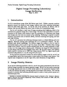
3. PRELIMINARY RESULTS In this section the findings of the approach are discussed. We have implemented the acquisition procedure (cf. Fig. 1) for the Android operating system,16 using the Samsung Galaxy S417 for testing. Furthermore, the OpenCV library was incorporated.18 In the following, the advantages resulting from our approach of automated and stable image acquisition as well as problems and optimization capabilities are outlined. As mentioned at the beginning, the use case for the presented image acquisition concept is banknote authentication using mobile devices.2 To make a statement on the authenticity of a banknote, features are extracted from a photography of a banknote, which subsequently are used for classification. To fulfill the requirement of consistent and reproducible results the object has to be captured under defined circumstances. One significant factor is the alignment of the mobile device and the object to be analyzed. Currently, the alignment as well as the triggering for image acquisition have to be performed manually by the user. The user is not capable for an exact and reproducible alignment such that captured images differ in scale and rotation and exhibit perspective distortions, caused by a non-parallel orientation of the device. In addition, while pressing the capture button, the device shakes slightly what leads to motion blurred images. These do strongly effect the subsequent authentication algorithms. Our approach overcomes this obstacles by supporting the user moving the device in correct position relative to the object and an automated triggering for image acquisition, depending on the motion of the device. This is not only useful in terms of banknote authentication but can be applied to other mobile image processing applications. The resulting advantages of an automated capturing process are versatile. One benefit is the significant improvement of user-friendliness to carry out image acquisition of a specific object. If the object is present in the cameras field of view, a continuous feedback in form of a framed object is given (cf. Fig. 2b), i.e. the user is aware of the ROI that has to be captured. In addition, the three Euler Angles (yaw, pitch and roll) representing the objects orientation are displayed. This simplifies and accelerates the complete procedure for handheld image acquisition. Another improvement for user-friendliness is the automated decision making for triggering the capturing process. Summarized, the boundary conditions for stable and consistent image acquisition become fulfilled with minimum expense for the user. Another improvement is concerning the image processing applications that are executed after image acquisition. Our approach enables to capture reproducible images with respect to the dimension and orientation of the object to be inspected. Therefore, the downstream algorithms obtain input images of consistent extent that only contain the required object information. For testing and to show the capabilities of our approach, we defined a target position for the object (cf. Fig. 4a). This is not a requirement since the general goal is to capture an image containing the complete object in a specific distance without an offset of rotation between the x- and yand z-axis relative to the device (parallel alignment). Therefore, the translational offset is not important for the subsequent object analysis. The results are depicted in Fig. 5, with respect to banknote authentication. The banknote (here a specimen) has to be completely visible in the camera view without geometric distortion caused by a misalignment of the mobile device. In Fig. 5b - d images captured using the presented approach are depicted. The black frame shows the target position for the object. In all three images the specimen nearly fits into the frame so that the subsequent authentication process can be applied to object images of consistent dimension and content. Note, the approach is capable to detect and capture an image of the object for varying backgrounds. In addition, non of the depicted images shows motion blur effects. This is because of the incorporated sensor fusion. Images are only captured if the Image Acquisition State is above a certain threshold (the device is in resting position). For that reason blurred images are avoided. Besides the benefits, also problems are present in our approach. One is apparent from Fig. 5c. The object does not entirely fit into the frame because of a translational offset. This is caused by the processing time the device needs to capture the image. The capturing process can not be influenced since it is an internal and nonaccessible Android-routine. Due to the time-frame between the trigger decision and the actual capturing, the
Proc. of SPIE-IS&T Vol. 9404 94040N-7
(a)
(b)
(c) (d) Figure 5: Resulting images of the presented acquisition concept. (a) The target position for the object in the camera view. (b) - (d) Images captured using the presented approach.
user possibly moves the device slightly, resulting in a offset for the object position or motion blur. In addition, the Image Acquisition State is currently not sensitive to constant velocity of the device because the available sensor information only states about the acceleration of the device that tends to zero for that case. Therefore, the capturing is may triggered while the device is moving, what also results in translational offset or motion blur. Another drawback is the focusing. It is executed during the capturing process, also handled by an internal Android-routine. Different focus modes exist like a continues adaption of the focus while the application is running or an autofocus-mode that focuses on a specific area of the image after image acquisition is triggered. We have observed that the focusing is not reliable and consistent. Thus, captured images might be blurred. This case we cannot avoid, since it is part of the devices firmware. As mentioned in Section 2.2, the Kalman filter is based on a linear model. Consequently, when the moving direction of the object changes abruptly, the filtered pose has a certain latency and tend to overshoot. However, if the relative velocity between the device and the object is nearly constant or small, these effects are small too and the Kalman filter enables a smooth object tracking. The complete process takes in average 72 ms per frame, i.e. the object position is updated 13.9 times per second, while the camera preview runs independently at 30 frames per second. The detailed times are given in Table 1.
4. CONCLUSION AND OUTLOOK 4.1 Conclusion We have presented new approach for stable image acquisition with mobile devices in the context of image processing applications. Arbitrary planar objects in a predefined position can be captured automatically with minimum effort for the user. Thus, it is applicable to a broad field of applications. By combining methods for pose and motion estimation the user is guided to move the device in correct position to the object. Because of the robust object detection approach by Taylor, Rosten and Drummond3 the object pose can be estimated
Proc. of SPIE-IS&T Vol. 9404 94040N-8
Process
Time [ms]
Grabbing frame from the Android camera interface Color convert Scaling Feature detection, description and matching Pose estimation Kalman filtering Miscellaneous
8 10 4 12 9 5 24
Total
72 Table 1: Average computation times per frame
in different environments (illumination, etc.) and for different object backgrounds. This is crucial since mobile devices are used in versatile environments. Additionally, pose stabilization and motion estimation are applied that enables for a fluently feeling feedback in form of a framed object to the user. Furthermore, the embedded sensors of the device are incorporated to state about its current motion and support the image acquisition. The latter is triggered automatically depending on the alignment of the device and the object as well as the Image Acquisition State, i.e. the aggregated sensor information. Since mobile devices are handheld, this is crucial and improves the acquisition procedure significantly. Effects like motion blur are suppressed and images of consistent dimension and content are captured. Therefore, subsequent image processing applications (e.g. banknote authentication using mobile devices) receive an appropriate input for further analysis.
4.2 Outlook As mentioned in Sec. 3, problems concerning the duration of the internal capturing process are present, resulting in blurred images or an offset for the object position. Additionally, the Image Acquisition State is not sensitive to constant motion of the device. In future work, concepts to overcome this problems will be investigated. The goal is to stabilize and improve the acquisition procedure further and capture consistent images in terms of image processing applications. Moreover, the integration of image quality metrics will be examined. On the one hand, to extend the fusion framework, on the other hand, to analyze images directly after capturing an reject those that do not fulfill the requirements of the application.
REFERENCES [1] Perera, C. and Chakrabarti, R., “The utility of mhealth in medical imaging,” Journal of Mobile Technology in Medicine 2(3), 4–6 (2013). [2] Lohweg, V., D¨ orksen, H., Hoffmann, J. L., Hildebrand, R., Gillich, E., Schaede, J., and Hofmann, J., “Banknote authentication with mobile devices,” in [Media Watermarking, Security, and Forensics], IST/SPIE Electronic Imaging 2013, San Francisco, USA (Feb 2013). [3] Taylor, S., Rosten, E., and Drummond, T., “Robust feature matching in 2.3µs,” in [IEEE CVPR Workshop on Feature Detectors and Descriptors: The State Of The Art and Beyond], (2009). [4] Rosten, E. and Drummond, T., “Machine learning for high-speed corner detection,” in [European Conference on Computer Vision ], 1, 430–443 (May 2006). [5] Lepetit, V., Moreno-Noguer, F., and Fua, P., “Epnp: An accurate O(n) solution to the pnp problem,” International Journal of Computer Vision 81(2), 155–166 (2009). [6] Kalman, R. E., “A new approach to linear filtering and prediction problems,” Transactions of the ASME– Journal of Basic Engineering 82(Series D), 35–45 (1960). [7] Welch, G. and Bishop, G., “An introduction to the kalman filter,” tech. rep., University of North Carolina at Chapel Hill, Chapel Hill, NC, USA (1995). [8] Brown, R. G. and Hwang, P. Y. C., [Introduction to random signals and applied Kalman filtering ], J. Wiley, New York (1992).
Proc. of SPIE-IS&T Vol. 9404 94040N-9
[9] Lohweg, V. and M¨ onks, U., “Sensor fusion by two-layer conflict solving,” in [The 2nd International Workshop on Cognitive Information Processing (CIP 2010) ], 370–375, IEEE, Elba Island (Tuscany), Italy (Jun 2010). [10] M¨ onks, U., Voth, K., and Lohweg, V., “An extended perspective on evidential aggregation rules in machine conditioning,” in [The 3rd International Workshop on Cognitive Information Processing (CIP 2012)], IEEE, Parador de Baiona, Spain (May 2012). [11] Shafer, G., [A mathematical theory of evidence], Princeton University Press, Princeton and N.J (1976). [12] Ahlawat, S. S., “Order effects and memory for evidence in individual versus group decision making in auditing,” Journal of Behavioral Decision Making 12(1), 71–88 (1999). [13] Lohweg, V., Diederichs, C., and M¨ uller, D., “Algorithms for hardware-based pattern recognition,” EURASIP Journal on Applied Signal Processing 2004(12), 1912–1920 (2004). [14] Zadeh, L. A., “Fuzzy sets,” Information and Control 8(3), 338–353 (1965). [15] M¨ onks, U. and Lohweg, V., “Machine conditioning by importance controlled information fusion,” in [18th IEEE International Conference on Emerging Technologies and Factory Automation (ETFA 2013)], 1–8, IEEE, Cagliari, Italy (Sep 2013). [16] Android, “Android development area,” https://developer.android.com/index.html (as-of 20 Dec 2014). [17] Samsung, “Samsung Galaxy S4 features,” http://www.samsung.com/uk/business/businessproducts/mobile-devices/smartphone/GT-I9505ZKABTU (as-of 20 Dec 2014). [18] OpenCV, “Opencv - open source computer vision library,” http://www.opencv.org (as-of 20 Dec 2014).
Proc. of SPIE-IS&T Vol. 9404 94040N-10