SPIE-IPv6: Single IPv6 Packet Traceback∗ W. Timothy Strayer, Senior Member, IEEE, Christine E. Jones, Fabrice Tchakountio, Member, IEEE, and Regina Rosales Hain BBN Technologies 10 Moulton Street, Cambridge, MA 02138 {strayer, cej, ftchakou, rrhain}@bbn.com Abstract The Source Path Isolation Engine (SPIE), developed at BBN, provides accurate tracing of single IP packets through a network. The SPIE system calculates several small hash values for each packet as it traverses a router, then stores these values in a data structure called a Bloom filter. Given a packet and an approximate time that packet was in the network, the SPIE system queries routers along the potential reverse path; a packet was “seen” at a router if the Bloom filter has stored the packet’s hash values. The SPIE system has been proven to work effectively and efficiently for IP version 4, largely because an IPv4 packet has sufficient entropy in the first 28 bytes to allow the hash functions to “uniquely” identify each packet. In this paper, we extend the traceback architecture to IP version 6, with the interesting result that the packet structure of IPv6 does not provide as much entropy in the field values as IPv4.
1. Introduction BBN Technologies developed the Source Path Isolation Engine (SPIE), a hash-based technique for IP traceback that generates audit trails for traffic within a network. The audit trails are used to trace the origin of any single IP packet delivered by the network in the recent past. The goal of SPIE, which was successfully attained, was to demonstrate that the system is effective, space efficient and implementable in current or next-generation routing hardware. The SPIE system was initially developed for IP version 4 [10] because of that version’s ubiquity in the Internet. Results of this development are reported in Snoeren et al. [11] and in various architecture and design documents available on the public SPIE web site.1 However, with the increasing deployment of IP version 6 [5], we have undertaken a study to determine the changes required of the IPv4-based SPIE system such that SPIE provides the same single packet traceback functionality in an IPv6 network environment. Also, the goals that SPIE be both effective and efficient still apply. This paper is the result of that study. ∗ 1
BBN is grateful to Matsushita Electric Works for its support of this work. http://www.ir.bbn.com/SPIE
2. Source Path Isolation Engine The Source Path Isolation Engine (SPIE) is a log-based traceback system that uses efficient auditing techniques at network routers to support the traceback of individual IP packets. Traffic auditing is accomplished by computing and compactly storing packet digests rather than storing the packets themselves. Every packet traversing a SPIE-enhanced router is recorded in a digest table; digest tables are paged at a specified rate and are representative of the traffic forwarded by the router during a particular time interval. A cache of digest tables is maintained for recently forwarded traffic. If a packet is determined to be offensive by some intrusion detection system (or judged interesting by some other metric), a trace request is dispatched to the SPIE system which in turn queries routers for packet digests of the relevant time periods. The results of this query are used in a simulated reverse-path flooding algorithm to build an attack graph that indicates the packet’s source(s). Historically, tracing individual packets has required prohibitive amounts of memory; one of SPIE’s key innovations is to reduce the memory requirement (down to 0.5% of link bandwidth per unit time) through the use of Bloom filters [1]. By storing only packet digests, and not the packets themselves, SPIE also does not increase a network’s vulnerability to eavesdropping. Therefore, SPIE’s hash-based traffic auditing allows routers to efficiently determine if they forwarded a particular packet within a specified time interval while maintaining the privacy of unrelated traffic.
2.1. Bloom Filters One of the fundamental functions performed by the SPIE system is recording evidence that a particular packet passed through a particular router. This evidence is collected in the form of a digest, or hash, over certain parts of the packet to uniquely identify that packet. The result of the digest function is a hash value. This hash value is stored in a Bloom filter [1], as shown in Figure 1. To be more precise, the Bloom filter is a single-bit array, and the hash value is an index into the array; setting the bit position in the array indexed by the hash value indicates that a packet whose hash value is that index was seen. To reduce false positives that occur when two different packets hash to the same value, the Bloom filter specifies using k independent hash functions, where each n-bit hash value becomes an index into a 2n single-bit ar-
H1 (P) 1 H2 (P)
DGA
DGA
Router
1
Router Router
Router Router
2n
H3 (P)
bits
. . .
1
Hk (P)
1
SCAR
Router
ISP's Network DGA
Router
STM
Router
n bits
Figure 2. The SPIE Architecture
Figure 1. SPIE use of a Bloom Filter
ray. The array is initialized to all zeros, and bits are set as packets are received. To check if a particular packet has been seen, that packet is hashed using each of the hash functions, and if all of the bit positions in the array indexed by these hash values is set to one, then the packet is declared to have been seen. An independent Bloom filter is constructed at or near each router so it can record all of the packets for the corresponding router. Eventually, a certain density is reached in the Bloom filter, and it is paged out and a new Bloom filter is inserted as the digest table. A paged-out digest table represents the set of traffic forwarded by the router for a particular interval of time. Each digest table is annotated with the time interval and the set of hash functions used to compute the packet digests over that interval.2
2.2. Hash Functions SPIE places three major restrictions on hash functions used as digesting functions in its Bloom filters. First, each function must distribute a highly correlated set of input values (i.e., packet prefixes) as uniformly as possible over the hash’s result space. SPIE further requires that packet collisions in one hash function be independent of collisions in any other function; intuitively, this implies that false positives at one router are independent of false positives at neighboring routers. Finally, hash functions must be straightforward to compute at high link speeds, which is not impractical because SPIE hash functions are not required to be cryptographically “hard”. The generation of a valid input packet given a particular hash value does not need to be difficult. The ability to create a packet with a particular hash value enables three classes of attacks, each of which is fairly benign. One attack ensures that all attack packets have the same fingerprint in the Bloom filters at some router (which is very difficult since there are multiple, independent hashes at each router), but this achievement is of little use, 2
For additional information about Bloom filters usage in the context of SPIE, please refer [11],section 4.B.
as the packet fingerprints would be distinct at neighboring routers (due to the independent hash functions at each router).3 Another attack is to ensure all attack packets have different fingerprints, but that is the common case already. The third, and most difficult attack, is to create an attack packet with the same fingerprint as another, non-attack packet. In general, this attack simply adds one additional false positive to the attack graph.
2.3. SPIE Architecture The tasks of packet auditing, query processing, and attack graph generation are dispersed among separate components in the SPIE system. Figure 2 shows the three major architectural components of the SPIE system. Each SPIE-enhanced router has a Data Generation Agent (DGA) associated with it. The DGA produces packet digests of each packet as it is forwarded through the router, and stores the digests in time-stamped digest tables. The digest tables are stored locally at the DGA for some period of time, depending on the resource constraints of the router. SCARs—SPIE Collection and Reduction Agents—are responsible for a particular region of the network, serving as data concentration points for several routers and facilitating traceback of any packets that traverse the region. When a trace is requested, each SCAR produces an attack graph for its particular region. The attack graphs from each SCAR are grafted together to form a complete attack graph by the SPIE Traceback Manager (STM). The STM controls the whole SPIE system. The STM is the interface to the intrusion detection system or other entity requesting a packet trace. When a request is presented to the STM, it verifies the authenticity of the request, dispatches the request to the appropriate SCARs, gathers the resulting attack graphs, and assembles them into a complete attack graph. Upon completion of the traceback process, the STM replies to the intrusion detection system with the final attack graph.
3
An attacker would be smart to avoid generating attack packets that collide because such behavior only strengthens SPIE’s traceback results.
2.4. Transformations It is important to note that packets may be modified during the forwarding process. In addition to the standard decrementing of the time to live (TTL) field and checksum recomputation, IP packets may be further transformed by intermediate routers. Such transformation includes: • Use of the source route option, where the destination IP address gets changed at each hop • IP tunneling, where one packet is encapsulated at one router and de-encapsulated at another • IP fragmentation, where one packet becomes several if the maximum transmission unit size for an interface is smaller than the size of the packet • ICMP query messages, where a request packet causes a router to generate a response • ICMP error messages, where a normal but undeliverable packet causes the router to generate a report explaining why the packet was dropped (for example, insufficient TTL, which is the trick traceroute uses) SPIE is capable of tracing through valid packet transformations by reconstructing the original packet from the transformed packet during the traceback process. Unfortunately, many transformations are not invertible without additional information due to the stateless nature of IP networks. Consequently, some additional packet data must be recorded by SPIE in an ancillary data structure (called the transform lookup table) at the time of transformation so that a sufficient amount of the original packet is able to be reconstructed. Some transformations may be reversible or predictable, such as Type 0 routing header changes, and not require additional data to be stored by SPIE. However, reconstructing the original packet requires more exceptional processing than SPIE desires.
2.5. Traceback Processing Before the traceback process can begin, an attack packet must be identified. Most likely, an intrusion detection system will determine that an exceptional event has occurred and provide the STM with a packet, P, victim V , and time of attack, T . SPIE places two constraints on the intrusion detection system: The victim must be expressed in terms of the last-hop router, not the end host itself, and the attack packet must be identified in a timely fashion. The first requirement provides the query process with a starting point; the latter stems from the fact that traceback must be initiated before the appropriate digest tables are overwritten by the DGAs. This time constraint is directly related to the amount of resources dedicated to the storage of traffic digests. Upon receipt of a traceback request, the STM dispatches the query to the relevant SCARs for processing. Beginning at the SCAR responsible for the victim’s region of the network, the STM sends a query messages containing P, V , and T as provided by the intrusion detection system. The SCAR polls its DGAs and responds with a partial attack graph, the time T 0 the packet entered the region, and the entering packet itself P 0 (it may have been transformed, possibly multiple times, within the region).
The attack graph either terminates within the region managed by the SCAR, in which case a source has been identified, or it contains nodes at the edge of the SCAR’s network region. In the latter case the STM sends a new query for the transformed packet P 0 to the SCAR for the abutting network region. This query uses the border router between the two network regions as its victim V 0 , and T 0 as the time of attack. This process continues until all branches of the attack graph terminate, either at a source within the network, or at the edge of the SPIE system. The STM then constructs a composite attack graph which it returns to the intrusion detection system.
2.6. Implementation Issues The SPIE architecture, although designed with IPv4 in mind, is actually protocol independent. In fact, SPIE does not even depend on the IP protocol—the SPIE architecture and traceback processing, including the SPIE traceback protocol, are sufficiently generic to trace any type of packet. The reason is that the high-level concepts of packet digesting and transformation recording are not protocol specific. However, the design specifics and implementation of the packet digesting and transformation recording functions are very much dependent on the actual protocol involved. SPIE was originally developed for IPv4 only because of IPv4’s ubiquity. Implementing SPIE for another type of packet—in this case, IPv6 packets— requires understanding the IPv6 packet structure, the mutability of the field values, and how IPv6 packets are processed at a router. Following the same design logic as we did with IPv4, we are able to determine the manner in which digesting and transformations are to be handled for IPv6, including the practicality and efficiency of SPIE in the IPv6 environment. The next section looks packet digesting, first through the design analysis for IPv4, then through a similar analysis for IPv6.
3. Digest Input Analysis The effectiveness of the SPIE system hinges on storing the very least amount of information necessary to determine with a high degree of certainty that a given packet passed through this router. Three somewhat disparate requirements must be considered in determining the optimal digest input of a packet. 1. Unique packet representation: To decrease digest collisions, the digest input must uniquely represent every packet. Two different packets should not produce identical digest input. 2. Identical digest input: The digest input of a packet must be identical at all hops along the forwarding path to produce a trail of identical digests for traceback. 3. Limited digest input size: It is desirable to limit the size of the digest input both for performance and for reducing the amount of data needing to be stored in the case of transforms. This section reviews how SPIE performs a digest over IPv4 packets, then specifies how a similar function should be performed for IPv6 packets.
3 4
7 8
Version IHL
15 16
19 20
31
1
Total Length
TOS
. . . . . . . . . IP ID . . . . . . . . . Flag TTL
23 24
Protocol
Checksum
Source Address Destination Address .. .
Options
WAN LAN
0.1
Fragment Offset
Fraction of Collided Packets
0
.. .
0.01
0.001
0.0001
1e-05
1e-06 20
22
24
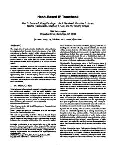
3.1. IPv4 Digesting The IPv4 packet structure, shown in Figure 3, specifies the Version (4, for IPv4), the length of the IPv4 header (IHL, typically 20 bytes, but may be longer if options are included), Type of Service (ToS), the Total Length of the IP packet, a unique packet identifier for use in fragmentation (IP ID), Flags to describe the type of packet, additional fragmentation information (Fragment Offset), a time-to-live counter (TTL), a Protocol identifier to specify the format of the next header in this packet), a header Checksum, and the Source and Destination Addresses. Additionally there may be some Options included that make the IPv4 header length longer than 20 bytes. SPIE computes packet digests over a subset of the IPv4 header fields and the first 8 bytes of the packet payload as part of the process for keeping unique evidence that a particular packet has been seen. Mutable fields—those that have the possibility of being changed at a router along the path—are masked prior to digesting, shown as shaded fields in Figure 3. In order to assure that a packet appears identical at each hop along its traversed route, it is necessary to mask out mutable fields. The type of service (ToS), total length, flags, fragment offset, time to live (TTL), checksum, and IP option header fields are masked out for all packets. (The IP ID field will also be masked when the packet is an ICMP echo.) If the packet is source routed, then the ultimate destination address is digested in place of the destination address in the packet. If the payload contains an ICMP timestamp or ICMP address mask request then the ICMP checksum must also be masked out. It is important to ensure that the input into the digest function provide sufficient entropy—that is, changes in input values from packet to packet—for the resulting hash value to uniquely identify a packet. Our research indicates that the first 28 bytes of a packet (20-byte IPv4 header plus the first 8 bytes of payload) are sufficient to differentiate almost all non-identical packets. Figure 4 presents the rate of packet collisions for an increasing prefix length
28
30
32
34
36
38
40
Prefix Length (in bytes)
64 bits of Payload
Figure 3. IPv4 header format
26
Figure 4. The fraction of packets that collide (with mutable fields masked out) as a function of prefix length
for two representative traces: a WAN trace from an OC-3 gateway router, and a LAN trace from an active 100Mb Ethernet segment. (Results were similar for traces across a number of sites.) Two unique packets which are identical up to the specified prefix length are termed a collision. A 28-byte prefix results in a collision rate of approximately 0.00092% in the wide area and 0.139% on the LAN.
3.2. IPv6 Digesting Porting SPIE to an IPv6 network environment requires analysis similar to that conducted for IPv4: The IPv6 header must be analyzed for mutable fields and for sufficient entropy. It is necessary to find the set of fields that do not change (that is, are immutable) from the source to the destination. These immutable fields will form part of the input to digest function. Once the set of immutable fields is determined, the amount of entropy must then be determined. This suggests how far into the packet the digest function must look for input so that the resulting hash value is sufficiently unique. 3.2.1. The IPv6 Header The IPv6 header format is slightly simpler but longer. The 40-byte header, shown in Figure 5, includes just eight fields: Version The Version field carries semantics identical to the IPv4 Version field. It contains the value 6 and is immutable. Traffic Class The Traffic Class field is an 8-bit field similar to IPv4 Type of Service (ToS) field. Traffic Class tags the packet with a value representing a class of traffic that can be used in Differentiated Services. The Traffic Class field, therefore, is intended to allow functionality similar to that in IPv4. It remains generally unchanged along the path to the destination, but may be mutable in certain situations. Indeed, RFC 2460 [5], states that routers that support a specific use of some or all the Traffic Class bits are permitted to
0
3 4
11 12
Version Traffic Class
Payload Length
16
31
24
Flow Label Next Header
Hop Limit
Source Address
16 bytes
Destination Address
16 bytes
Figure 5. IPv6 header format
change the value of those bits in packets they forward as required for that specific use. Consequently, the Traffic Class field can not be considered immutable. Flow Label The Flow Label field is used to tag packets of a specific flow to differentiate the packets at the network layer. With this label, the router need not check deep into the packet to identify characteristics that would suggest a particular flow. Routers must not change Flow Label as packets travel to the destination. Payload Length The Payload Length field is similar to IPv4 Total Length field. Payload Length indicates the total length of the data portion of the packet. For a regular packet, it does not change along the path to the destination. The SPIE architecture for IPv4 requires the Total Length field to be masked out in order to make fragmentation transparent to the SPIE system. In IPv6, fragmentation is no longer performed by routers. Consequently, Payload Length need not be masked out. Next Header The Next Header field is similar to the IPv4 Protocol field. The value of Next Header determines the type of information following the IPv6 header. The type of information can be either a transport layer header (TCP, UDP) or an Extension Header. The Next Header value is immutable along the path to the destination. Hop Limit The Hop Limit field is similar to IPv4 Time-toLive (TTL) field in that it specifies the maximum number of routers that an IPv6 packet can traverse before the packet is considered invalid. The Hop Limit value is typically decremented by one at each router, so the field does not remain immutable over the whole path of the packet.
Source and Destination Addresses The Source and Destination Address fields are similar to the same fields in IPv4 except that they are 128 bits in length rather than 32. The Source Address field is an immutable field over the whole path of the packet. The Destination Address field is similar to the Destination Address field of IPv4 in that, in general, it is an immutable field, but there is one exception. In case of Type 0 Routing Header (the IPv6 equivalent of Source Route option from IPv4), the Destination Address field carries the address of a next hop, which may not be the ultimate destination. In this case, the ultimate destination’s address as contained in the Routing Header must be extracted and used for digesting rather than Destination Address. This is precisely what is done in SPIE for IPv4 Source Routing. Header fields that have the possibility of being changed at a router along the path are masked prior to digesting, shown as shaded fields in Figure 5. For the IPv6 header, the two header fields are the Traffic Class and the Hop Limit. 3.2.2. IPv6 Extension Headers To compensate for the lack of flexibility in the IPv6 header, the IPv6 protocol specification allows for an arbitrary number of extension headers to follow the IPv6 header adding information that, to a large extent, is to be conveyed from the source to the destination. A full implementation of IPv6 includes implementation of the following extension headers: • Hop-by-Hop Options Header • Type 0 Routing Header • Fragment Header • Destination Options Header • Authentication Header • Encapsulating Security Payload With the exception of the Hop-by-Hop Options header, extension headers are not examined or processed by any node along the packet’s path, until the packet reaches the node identified in the destination address specified in the IPv6 header. Following is a brief description of each extension header and a determination of which bytes of which headers will be used as part of the input for the digest function: Hop-by-Hop Options Header The Hop-by-Hop Options Header is used to carry optional information that must be examined by every node along a packet’s delivery path. Since it is possible to be changed on a hop-by-hop basis, no bytes from it will be used as input for digest. Type 0 Routing Header The Type 0 Routing Header is used by an IPv6 source to list one or more intermediate nodes to be “visited” on the way to a packet’s destination. This function is very similar to the IPv4’s Loose Source and Record Route option. For SPIE IPv6, the ultimate packet destination specified in this header will be used as the destination address for input in the digest function. All other bytes in this header will be ignored and not considered as input for digest. All other Routing Header types, if there are any others, will not be considered as input for digest.
3.3. IPv6 Digesting Algorithm and Analysis The digesting algorithm for IPv6 packets starts with the 40 bytes of the IPv6 header with the Traffic Class and the Hop Limit fields masked out. Our experience with digesting IPv4 headers suggests that the IPv6 header fields themselves do not provide enough entropy, so the extension headers must also be included as input. Since we cannot know when a sufficient number of extension headers have been included as input to the digest algorithm, the algorithm simply includes all appropriate ones, masking out the mutable portions as described above. Whole extension headers that will not be included in the digest input are the Hop-by-Hop Options Header and the Destination Options Header. Only the final destination field of the Type 0 Routing Header will be included in the digest input. If a Type 0 Routing Header is included in the packet, the final destination in the header substitutes for the IPv6 destination address. All of the Fragment Header, Authentication Header, and the unencrypted part of the Encapsulation Security Payload Header will be used as part of the digest. The encrypted part of the Encapsulation Security Payload Header is considered as the IPv6 payload data. To ensure sufficient entropy like in IPv4, our research indicates that, along with the IPv6 header and various bytes from the extension headers, including the first 20 bytes of payload is sufficient to differentiate almost all non-identical packets. Figure 6 presents the rate of packet collisions for an increasing prefix length, starting at the payload data, for traces taken on the 6-bone. As in the IPv4 study, two unique packets which are identical up to the specified prefix length are termed a collision. Different from the IPv4 study is that in the IPv6 study, the prefix length refers to the start of payload data. Each IPv6 packet is likely to have extension headers and the length of extension headers from packet to packet is likely to vary. To uniformly identify the notion of prefix length, the IPv6 study uses the beginning of payload data. Packets hashed
1
Fraction of Collided Packets
Destination Options Header The Destination Options Header is used to carry optional information that need be examined only by a packet’s destination node. Since it is possible to be changed on a hop-by-hop basis if combined with a Type 0 Routing Header, no bytes from it will be used as input for digest. Fragment Header The Fragment Header is used by an IPv6 source to send a packet larger than would fit in the path MTU to its destination. All 8 bytes of the header will be used as input for the digest. Authentication Header The IP Authentication Header (AH) is used to provide connectionless integrity and data origin authentication for IP datagrams, and to provide protection against replays. All the bytes in the IP AH will be used as input for the digest. The length of the header is calculated based on the payload length field that is contained within the header. Encapsulating Security Payload The Encapsulating Security Payload (ESP) is designed to provide a mix of security services for IPv6, such as confidentiality, data origin authentication, connectionless integrity, an anti-replay service, and limited traffic flow confidentiality. Only the first 8 bytes of ESP will be used as input for the digest.
0.1
0.01
0.001 0
5
10
15
20
25
Prefix Length (in bytes)
Figure 6. The fraction of packets on the BBN 6bone segment that collide as a function of prefix length
to 20 bytes of payload data results in a collision rate of approximately 0.1964%. We want to include the destination address in the digest algorithm, but the destination address may change if the Type 0 Routing Header is present. Unfortunately, we cannot know this until we have processed all of the extension headers. As an optimization to the digesting algorithm, the destination address will be the last 16 bytes given to be digested. This is done to allow pipelining of the digest function input even in the event that a Type 0 Routing header is encountered in the packet. If a Type 0 Routing header is encountered, the destination address will be the final destination specified in the Type 0 Routing header instead of the original destination address specified in the IPv6 header. The maximum number of bytes from the IPv6 packet to be used as input to the digest function is determined somewhat by the inversion of certain transforms, in particular, the ICMPv6 error messages. An ICMPv6 error message returns in its payload as much of the offending packet as possible. Since the minimum MTU for IPv6 is 1280, the largest amount of an offending packet that can be included in an ICMPv6 error message is 1232 bytes: 1280 bytes minus the IPv6 header (40 bytes) minus the ICMPv6 header (8 bytes). Consequently, the digest algorithm will take no more than 1232 bytes of input, including the IPv6 header, the extension headers, and up to 20 bytes of payload. SPIE’s performance is often characterized by the amount of false routers (false positives) included in an attack graph. False positives in an attack graph are directly related to the rate of false positives incurred by a router’s digest table (see [11], Section 4). The false positive rate of the digest table depends on several factors including the “uniqueness” of the packet. Indeed, if a chosen digest input for a packet results in lots of collisions, then the false positive rate of the digest table will increase. Fortunately for SPIE, the difference in digest input between IPv4 and IPv6 does not cause a significant rise in collision rates with IPv6. In fact,
the collision rates are so low (< 0.2%) for IPv6 that one can say that the uniqueness of the packet is preserved. If the amount of resources (that is, memory) dedicated to the digest tables remains the same as in IPv4, then the false positive rates generated in IPv6’s attack graphs will be identical to those of IPv4 in the worst-case scenario. That is, any true attack graph of n routers will have at most np/(1 − p) extra routers in expectation if the false positive rate of the digest table is at most P = p/d; where 0 ≤ p/d ≤ 1, p is an arbitrary tuning factor and d is the router’s degree.
4. Transformations As in IPv4, IPv6 packets may be modified during the forwarding process. In addition to the standard modifications discussed in Section 3.2, IPv6 packets may be further transformed by intermediate routers. Packet transformation inversion, whether IPv4 or IPv6, consists of creating the original packet from the resulting packet (since the trace is going backwards in time). The SPIE system must glean as much information as possible from the resulting packet in order to reconstruct the original packet, but sometimes some additional information must be stored at the point of transformation (the router that did the transforming). Packet transforms for IPv6 include the transforms described below. For each transform, the process used and the ancillary packet data, if any, required by SPIE for packet inversion is given. Type 0 Routing Header This is the equivalent of the IPv4 Source Route option. Like the IPv4 source route option, the presence of this header results in the modification of the destination address field of the IPv6 header. Like IPv4, the final destination is identifiable in this extension header. During the digesting process, the final destination address in the header should replace the destination address field of the IPv6 header prior to the digesting process. ICMPv6 Messages As in IPv4, SPIE must support the transforms associated with ICMPv6 messages, both error and informational (echo request/reply) [4]. Like IPv4, SPIE traces ICMPv6 error and echo request and reply messages generated by routers to the source of the original packet. Error Messages There is a notable difference between ICMP error messages and ICMPv6 error messages. Recall that ICMP error messages are generated when a packet causes a processing error in a router. While ICMP errors are required by RFC792 to include a portion of the original packet comprising the IPv4 header and at least the first 8 bytes of the payload, ICMPv6 errors are required to contain an original portion comprising the IPv6 header and as much of the data next to the header as fits without making the resulting ICMPv6 packet to exceed the minimum MTU. This means that the original packet contained in the ICMPv6 error message could be as long as 1232 bytes. (This accounts for the limit of how many input bytes are allowed for the IPv6 digesting function.) The traceback of the ICMPv6 error starts from the victim to the point where the ICMPv6 error message was created. Upon packet inversion, the original packet is extracted from the error message, with the destination field updated in the Routing Header case. At this point, the traceback continues with the extracted packet until the source.
Informational Messages The two ICMPv6 informational messages (echo and echo reply) maintain semantics and functionality similar to ICMP echo and echo reply. An ICMPv6 echo reply message is traced to the source of the original ICMPv6 echo request. The echo reply is a modified version of the corresponding request. The checksum field of the ICMPv6 header is recoverable, as fields that are updated (e.g., type field) within the entire ICMPv6 payload are deterministic. Thus, no ancillary data need be kept at the associate DGA of the transforming router. Upon traceback query, a DGA receives an ICMPv6 echo reply packet. The DGA reconstructs a version of the original ICMPv6 echo request and continues the trace with the packet carrying the request packet. IPv6 Tunneling Like IPv4, IPv6 tunneling [3] represents two packet transformations, encapsulation and de-encapsulation. At the encapsulating router, an outer IPv6 header is prepended to the unmodified original packet. Thus, the fact that encapsulation occurred need only be recorded by the DGA. No ancillary packet data is required for inversion. At the de-encapsulating router, the tunneled packet has its outer IPv6 header removed, at which point the original packet continues its journey toward the destination. Reconstruction of the tunneled packet upon traceback requires an IPv6 header to be prepended to the original packet. The entire IPv6 header of the original packet does not need to be recorded by the de-encapsulating DGA; instead, non-deterministic fields of the header such as Flow Label (20 bits), Source Address (128 bits), and Destination Address (128 bits) need to be stored to reconstruct the tunneled packet. IPsec Tunneling IPsec is a set of security specifications [9] originally written as part of the IPv6 specification. Due to an urgent need of security in IPv4, IPsec was also adapted for IPv4. Although IPsec is mandatory in IPv6 but optional in IPv4, IPsec functionality in IPv6 is identical to that in IPv4. IPv4/IPv6 Transforms Because there are often bridges between IPv4 and IPv6 networks, we consider transformations that convert from one protocol to the other or use tunnels to traverse one protocol’s enclave. Network Address and Port Translation NAT [7] has been designed originally as a short-term solution to the depletion of IPv4 addresses. For IPv6, one may assume that NAT is not required since IPv6 already solves the addressing problem. This assumption is true for IPv6-only domains. However, IPv6 is not yet ubiquitous, and some organizations rely sometimes on a NAT variant like NAT-PT [13] to ease the migration of their networks from IPv4 to IPv6. NAT-PT enables a node in an IPv6 domain to communicate with a node in an IPv4 domain (and vice-versa). To achieve this, NAT-PT uses a Protocol Translator (PT) to translate IPv6 packets to IPv4 packets (and vice-versa). NAT-PT uses a pool of IPv4 addresses for assignment to IPv6 nodes dynamically as sessions are initiated across IPv4-IPv6 boundaries. IP headers are mapped from one protocol to another using the address association and simple copying and adjustment of header field (e.g., TTL to Hop Limit). Checksum updates are performed on TCP/UDP/ICMP packets during the transformation. Further, NAT-PT may translate transport layer identifiers such as TCP/UDP ports. Applications, such
as FTP, may embed an IP address and TCP ports into packets that may be modified by the NAT-PT router. All the original and non-deterministic information replaced during NAT-PT transformation is unrecoverable, and must be available for packet inversion. The transforming DGA should store the non-deterministic data of the original packet, although this could prove to be costly in terms of memory resources. IPv6-over-IPv4 Tunneling A variety of tunneling mechanisms are available for deploying IPv6 over IPv4 tunnels [8, 6, 2]. In general, these mechanisms are either manual or automatic. Manual tunnel mechanisms include configured tunnels, and IPv6-overIPv4 GRE tunnels, while automatic tunnel mechanisms include IPv4-compatible tunnels, tunnel broker services [6], and 6to4 tunnels [2]. All these tunneling mechanisms have a behavior similar to native IPv6 tunneling in that they represent two forms of packet transformations, encapsulation and de-encapsulation. At the encapsulating router, an outer IPv4 header is prepended to the original IPv6 packet. The fact that an IPv6-over-IPv4 encapsulation occurred need only be recorded by the DGA. No ancillary packet data is required for inversion. Unlike IPv6 tunneling, the digesting algorithm applied to the tunneled packet follows the rules of IPv4 processing (see [12]), that is, it uses a subset of the IPv4 header fields and the first 8 bytes of IPv4 payload for digesting. At the de-encapsulating router, the tunneled packet has its outer IPv4 header removed, at which point the original IPv6 packet continues its journey toward the destination. Reconstruction of the tunneled packet upon traceback requires an IPv4 header to be prepended to the original IPv6 packet. The entire IPv4 header of the original packet does not need to be recorded by the deencapsulating DGA; instead, non-deterministic fields of the IPv4 header need to be stored to accurately reproduce the encapsulating header. These fields are: Header Length (16 bits), Identification (16 bits), and Source Address (32 bits). Destination Address (32 bits) needs to be recorded only for manual tunnels. IPv4-over-IPv6 Tunneling Currently standard specifications about IPv4-over-IPv6 tunneling issues are not yet available but will probably be when the IPv6’s presence on the Internet reaches significant proportions. Nonetheless, SPIE handling of IPv4-overIPv6 tunnels should be very similar to IPv6-over-IPv4 tunneling. Upon packet transformation, encapsulating IPv4-over-IPv6 routers should not require any storage of ancillary IPv4 packet data, and de-encapsulating IPv4-over-IPv6 routers should store only the non-deterministic information of the tunnel IPv6 header.
Unneeded IPv6 Transform Considerations There are some transforms that SPIE supports in IPv4 that are no longer relevant for IPv6, specifically, fragmentation and fragment reassembly. Unlike IPv4, fragmentation in IPv6 is preformed only by source nodes. Routers along a packet’s delivery path are not allowed to perform fragmentation. Fragment reassembly is done only at the IPv6 destination. If a Routing Extension Header is included in the IPv6 packet, the destination address is defined to be the final destination in the Routing Header. SPIE is not responsible for recoding traffic at the destination host.
5. Conclusion The Source Path Isolation Engine is a powerful traceback technique for IPv4 networks. Interest in IPv6 networks is increasing, so we undertook a study to design the SPIE system for IPv6. There were two key challenges—ensuring that the IPv6 packet input to the SPIE digest algorithm would provide enough entropy, and constructing an inversion strategy for each possible transformation a packet may encounter within a router. SPIE in an IPv4 environment requires only 28 bytes of input from an IPv4 packet to achieve the necessary entropy for the hashing algorithms to uniquely describe a seen packet. Interestingly, this is not the case for IPv6. An IPv6 header is much simpler (although larger) than the IPv4 header, with most of the sources of entropy have been moved to the extension headers. Consequently, the SPIE digesting algorithm for IPv6 must include as input all of the extension headers. Even so, we cannot be certain that this has provided enough entropy, so (as our experiment shows) we must include the first 20 bytes of the payload as well. Since IPv6 has a minimum MTU of 1280, this bounds the size of the digest input to the smaller of 1232 (1280 minus 40 minus 8) and the sum of the IPv6 header, the extension headers, and the first 20 bytes of payload. This sounds like a lot of digest input, especially compared to the 28 bytes of IPv4, but in practice the number of extension headers will likely be small.
References [1] B. H. Bloom. Space/time trade-offs in hash coding with allowable errors. Communications of ACM, 13(7):422–426, July 1970. [2] B. Carpenter and K. Moore. Connection of IPv6 domains via IPv4 clouds. RFC 3056, IETF, Feb. 2001. [3] A. Conta and S. Deering. General packet tunneling in IPv6 specification. RFC 2473, IETF, Dec. 1998. [4] A. Conta and S. Deering. Internet Control Message Protocol (ICMPv6) for the Internet Protocol version 6 (IPv6) specification. RFC 2463, IETF, Dec. 1998. [5] S. Deering and R. Hinden. Internet Protocol, version 6 (IPv6). RFC 2409, IETF, Nov. 1998. [6] A. Durand, P. Fasano, and D. Lento. IPv6 tunnel broker. RFC 3053, IETF, Jan. 2001. [7] K. Egevang and P. Francis. The IP Network Address Translator (NAT). RFC 1631, IETF, May 1994. [8] R. Gilligan and R. Nordmark. Transition mechanisms for IPv6 hosts and routers. RFC 2893, IETF, Aug. 2000. [9] S. T. Kent and R. Atkinson. Security architecture for the Internet Protocol. RFC 2401, IETF, Nov. 1998. [10] J. Postel. Internet Protocol. RFC 791, IETF, Sept. 1981. [11] A. Snoeren, C. Partridge, L. Sanchez, C. Jones, F. Tchakountio, B. Schwartz, S. Kent, and W. Strayer. Single-packet IP traceback. ACM/IEEE Transactions on Networking, Dec. 2002. [12] T. Strayer, C. Jones, F. Tchakountio, A. Snoeren, and C. Partridge. Source Path Isolation Engine Architecture. http://www.ir.bbn.com/projects/SPIE. [13] G. Tsirtsis and P. Srisuresh. Network Address Translation Protocol Translation (NAT-PT). RFC 2766, IETF, Feb. 2000.