TR-IIS-08-010
Smart Medication Dispenser: Design, Architecture and Implementation
P. H. Tsai, C. Y. Yu, C. S. Shih, Member, IEEE, and J. W. S. Liu, Fellow, IEEE
October 3, 2008
||
Technical Report No. TR-IIS-08-010
http://www.iis.sinica.edu.tw/page/library/LIB/TechReport/tr2008/tr08.html
Institute of Information Science, Academia Sinica Technical Report TR-IIS-08-010
Smart Medication Dispenser: Design, Architecture and Implementation P. H. Tsai, C. Y. Yu, C. S. Shih, Member, IEEE, and J. W. S. Liu, Fellow, IEEE Abstract This paper presents the architecture and implementation of an automatic medication dispenser specifically for users who take medications without close professional supervision. By relieving the users from the error-prone tasks of interpreting medication directions and administrating medications accordingly, the device can improve rigor in compliance and prevent serious medication errors. By taking advantage of scheduling flexibility provided by medication directions, the device makes the user’s medication schedule easy to adhere and tolerant to tardiness whenever possible. This work is done collaborative by the medication scheduler and dispenser controller in an action-oriented manner. An advantage of the action-oriented interface between the components is extensibility, as new functions can be added and existing ones removed with little or no need to modify the dispenser control structure. The paper first describes the action-oriented design, major components and hardware and software structures of the smart device. It then provides an overview of the heuristic algorithms used by the medication scheduler and their relative merits.
Copy right @ October 2008
P. H. Tsai and C. Y. Yu are affiliated with Department of Computer Science, National Tsing Hua University, Hsinchu, Taiwan. Their email addresses are
[email protected] and
[email protected]. C. S. Shih is affiliated with Department of Computer Science and Information Engineering, National Taiwan University. His email address is
[email protected]. J. W. S. Liu is affiliated with Institute of Information Science, Academia Sinica, Nankang, Taipei, Taiwan. Her email address is
[email protected]
1
Table of Contents ABSTRACT .................................................................................................................................................................1 1 INTRODUCTION ....................................................................................................................................................3 2 RELATED WORKS .................................................................................................................................................5 3 BACKGROUND AND ASSUMPTIONS ................................................................................................................7 3.1 A USE SCENARIO .................................................................................................................................................7 3.2 MEDICATION SCHEDULE SPECIFICATION ..............................................................................................................9 4 DISPENSER ARCHITECTURE...........................................................................................................................12 4.1 MAJOR SOFTWARE COMPONENTS ......................................................................................................................12 4.2 HARDWARE COMPONENTS AND DRIVER INTERFACE ..........................................................................................13 5 ACTION-ORIENTED COLLABORATION .......................................................................................................15 5.1 DECISION MAKER INTERFACE ............................................................................................................................16 5.2 COMMUNICATION FLOW ....................................................................................................................................18 6 CONTROLLER AND SCHEDULER COLLABORATION ..............................................................................19 6.1 CONTROLLER SOFTWARE STRUCTURE ...............................................................................................................19 6.2 ILLUSTRATIVE EXAMPLE ....................................................................................................................................22 7 HEURISTIC SCHEDULING ALGORITHMS....................................................................................................25 7.1 UNDERLYING MODEL.........................................................................................................................................25 7.2 ALGORITHM DESCRIPTIONS ...............................................................................................................................27 7.3 RELATIVE MERITS..............................................................................................................................................29 8 SUMMARY AND FUTURE WORK ....................................................................................................................35 ACKNOWLEDGEMENTS ......................................................................................................................................36 REFERENCES ..........................................................................................................................................................36
2
1 Introduction Thanks to years of advances in medical and pharmaceutical technologies, more and more drugs can cure or control previously fatal diseases and help people live actively for decades longer. The benefits of the drugs would be even more wondrous were it not for the high rate of preventable medication errors [1-5]. Medication errors are known to occur throughout the medication use process of ordering, transcription, dispensing, and administration. They lead to many hundred thousands of serious adverse drug events, thousands of deaths and billions of dollars in hospital cost each year in US alone. These alarming statistics have motivated numerous efforts in research, development and deployment of information technology systems and tools for prevention of medication errors (e.g., [6-25]). We now witness increasingly wider use of computerized physician order entry (CPOE) systems [6-11] in hospitals and clinics for prevention of prescription errors, which account for more than 50% of all errors. Data available to date show that together with clinical decision support [6] and electronic patient health and medication records (ePHR and eMAR) [7], CPOE systems can help prevent up to 80% of prescription errors, i.e., 40% of all errors. Next to prescription errors, administration errors (i.e., errors due to failures to compliant to medication directions) are the most prevalent: They contribute 25 – 40% of all preventable errors and are the cause of 25% of admissions to nursing homes [5]. The smart medication dispenser described in this paper is designed to prevent this type of errors. It is primarily for the growing population of users who are elderly or have chronicle conditions but are well enough to live independently. Such a user may be on many prescribed and over the counter (OTC) medications for months and years without close professional supervision. Specifically, our smart dispenser is designed to eliminate two most common causes of administration error: misunderstanding of medication directions and inconvenience of rigid medication schedules. Being almost fully automatic, the dispenser schedules individual doses of 3
the user’s medications under its care based a machine readable medication schedule specification (MSS) extracted from the user’s prescriptions and directions. (We will discuss in Sections 2 and 3 the content and generation of the specification.) It then reminds the user at the times when some doses should be taken, monitors user’s response to reminders, adjusts the medication schedule as needed when the user is tardy, and when non-compliant becomes unavoidable, sends notification in ways specified by the user. In this way, the dispenser helps its user follow directions and stay compliant without having to understand the directions. This work is done collaboratively by the dispenser controller and medication scheduler in an action-oriented manner. An advantage of this design is generality and extensibility: As it will become evident in later sections that actions and action handlers can be added or removed to configure the device or to build a different device with little or no need for modification of the control structure of the dispenser controller. By taking advantage of scheduling flexibility provided by directions of most modern medications, the dispenser makes the user’s medication schedule as easy to adhere and tolerate to user’s tardiness as possible. It uses two families of heuristic scheduling algorithms for this purpose [26, 27]. One-Medication-at-a-Time (OMAT) algorithms produce a full schedule for each of the medications listed in the MSS in turn, while One-Dose-at-a-Time (ODAT) algorithms schedule the individual doses of the medications one at a time. Performance data obtained via simulation show that OMAT algorithms are more likely to succeed in finding schedules that meet the constraints defined by the MSS. The dispenser scheduler uses one of these algorithms to generate a complete schedule initially. Being on-line, ODAT algorithms offer good alternatives when the schedule needs to be adjusted to compensate for user’s tardiness. The remainder of the paper is organized as follows: Section 2 presents an overview of tools that provide support for smart dispensers and compare our dispenser with other medication usage assistance devices. Section 3 presents key assumptions that must be valid for our dispenser to work, illustrates its operations by a user scenario and describes the timing and dosage constraints
4
parameters defined by MSS. Section 4 presents the architecture and hardware and software components of the dispenser. The prototype software of the dispenser has an action-oriented structure. Section 5 describes the structure in general, together with the interface and communication flow for action-oriented collaboration. Section 6 describes the software control structure of the dispenser controller designed to support its action-oriented collaboration with the medication scheduler and illustrates their collaboration with an example. Sections 7 provides an overview of the OMAT and ODAT algorithms and their relative performance. Section 8 summarizes the paper and discusses future work. 2 Related Works Figure 1 shows an integrated chain of information systems and tools that complements each other to prevent medication errors throughout the medication use process (e.g., [12-14]). CPOE systems [6-11] are at the start of the chain. Like other medication administration assistance tools, our smart dispenser sits at the end-user end of the chain. Transcription and dispensing stage tools, as exemplified by the prescription authoring tool shown in the figure, link dispensers and integrate them into the chain.
CPOE1
CPOE 2
CPOE n
Clinical Decision Support
Prescription 1
Prescriptioni 1 Prescription
Drug Library
ETL (Extract, Transform and Load) ePHR Standard Prescriptions
Compiler
Verifier
User’s eMAR
Prescription Authoring Tool
Medication Schedule Specification (MSS)
Figure 1 Tools for prevention of medication errors
A typical user is likely to be cared by multiple physicians and given prescriptions ordered via 5
independent CPOE systems. While each of the user’s prescriptions is error free, it may fail to account for interactions between medications ordered by different prescriptions. A major function of the prescription authoring tool described in [17] is to help user’s pharmacist detect and eliminate this kind of error. Another important function of the tool is the generation of medication schedule specifications that guide the operations of the dispensers. The tool first merges all of user’s prescriptions and OTC medication directions and then translates the merged directions thus generated into a MSS, written in XML language, for the user’s dispenser. The tool also makes sure that all the constraints defined by MSS for each medication are feasible, i.e., there is at least a schedule meeting the constraints if the medication were to be scheduled alone. The demand-versus-supply test (DST) described in [18] is for this purpose. There are a large variety of medication administration assistance devices for non-professional users. Unlike our dispenser, most stand-alone devices (e.g., [19-22]) available today are manual: A disadvantage of a manual device is that the user must load the individual doses of medication into the device, understand their directions and program the device to send reminders accordingly. This manual process frequently introduces errors. Like schedules used by our dispenser, medication schedules used by automatic devices and scheduling tools such as MEDICATE Tele-assistance System [23, 24] and Magic Medicine Cabinet [25] can be adjusted to compensate for user tardiness and condition changes. The adjustments are by care providers who monitor and supervise the user via Internet, however. Those devices are better suited for users who need close professional supervision and fully integrated health care services. In contrast, our dispenser is a stand-alone tool, capable of making schedule adjustments permitted by existing prescriptions. It is for individuals who are well and hence do not want to incur the cost of continuous monitoring and care and consequent loss of privacy and independence.
6
3 Background and Assumptions For any automatic medication dispenser serving a single user at home and work to be effective in prevention of medication errors, the following restrictive assumptions must be valid: (1) The tool manages all prescribed and OTC medications of the user. (2) The medication schedule specification (MSS) used to guide the operations of the dispenser is generated based on a complete and current medication record of the user. These are our assumptions. Although the dispenser does not handle food, it must schedule meals and snacks along with medications when food interferes with some of the user’s medications. 3.1 A Use Scenario A possible scenario for the above mentioned assumptions to be valid is that the user acquires all of his/her medication supplies from a single pharmacy, and the pharmacist serving the user has access to all of user’s medication-related information (e.g., current prescriptions and allergies). When the user comes to fill a new prescription or purchase some OTC drugs and health supplements, the pharmacist uses a prescription authoring tool [17] or a similar tool to process the user’s new and existing prescriptions and generate a MSS for the user’s dispenser. The pharmacist provides the MSS to the user, along with new supplies of medications in containers. Each container holds the medication identified by the RFID tag attached to the container. Figure 2 shows the dispenser parts that interact with the user. The MSS is stored in a flash disk. The dispenser has on its base a number of sockets, an indicator light around each socket, a reminder (i.e., an audio alarm, or a flashing light, or a phone, etc.), a text display, a LED display, a Push-To-Dispense (PTD) button, verification boxes, a dispensing drawer and a USB port. The RFID reader for reading tags on containers sits inside the base. Containers holding medications taken by the user are plugged in sockets. There is a switch inside the base for each socket. The switch is closed when a container is plugged in the socket; otherwise it is open. 1) Set up In order to put new supplies under the care of the dispenser, the user plugs the MSS 7
disk into a USB port of the dispenser and all the new containers into empty sockets in any order. The dispenser picks up from the MSS disk the updated medication list and constraints for scheduling the new medications along with existing ones. Whenever the dispenser controller senses that the state of the switch for a socket (say socket number k) changes from open to close, it commands the RFID reader to read the tags on all containers in sockets. Upon discovering a new id (say M), it creates and starts to maintain the id-location mapping (M, k) for the new medication and locks the container in socket. Containers RFID tag MSS
MSS flash disk Indicator light
Reminder LED display
Socket
Text display Verification box PTD
Dispensing drawer
Dispenser base
Figure 2 Parts of a smart dispenser
The controller can correctly locate the container for every medication under its care only if it disallows multiple containers being plugged in at the same time. In the rare event when it senses that the user has plugged in more than one container, the dispenser prompts the user to remove the containers involved and plug them back again one at a time. 2) Normal Operations Set up completes and normal operations commence when the dispenser base holds a container and has the id-location mapping for every medication listed in the MSS. The dispenser first computes a medication schedule, which specifies the time instants and dose sizes of medications to be taken. We will refer to these time instants as dose times hereafter. Shortly before each dose time, the dispenser uses the reminder to tell the user to come to take medication(s). In response, the user reports to the dispenser by pushing the PTD button. 8
Because the time the user takes to respond to a reminder may vary widely, the dispenser updates the dose size of each medication due to be taken whenever the PTD button is pushed. For each medication due to be taken, the dispenser lights up the indicator light around the socket holding the container for the medication and unlocks the socket to allow the removal of the container. When the user picks up the container, the LED display shows the dose size to be taken at the time. After the user retrieves the indicated dose from the container and puts the container back to the socket, the dispenser locks the container in place again. The dispenser and the user repeat this collaborative process if there is more medication(s) scheduled to be taken at the time. A dispenser with the verification capability is equipped with a camera to capture the image of objects placed in verification boxes. The user needs to put each retrieved dose in a verification box. Once there, the dispenser checks visually whether the retrieved dose size is correct. It uses the text display to instruct the user when correction is necessary, and when there is no error, locks the returned container in place and drops the medication into the dispensing drawer. 3.2 Medication Schedule Specification As we will see in later sections, user’s medication schedule is computed and adjusted by the medication scheduler based on the firm and hard timing and dose size constraints given by the MSS of the user. Whenever possible, the normal medication schedule is such that all firm constraints are met if every dose is indeed retrieved by the user as scheduled. Deviations from normal schedule may occur, mostly due to user’s tardiness, and some may lead to violations of hard constraints. The dispenser treats each violation of a hard constraint as a non-compliance event and is required to take some specified action(s) (e.g., contact a care taker). Specifications on the actions required to handle each type of non-compliance events are included in the MSS. This aspect is out of the scope here. A smart dispenser may accept user input on preferred times and frequencies for taking medications and treats user preferences as soft constraints to be met on a best effort basis. Due to space limitation, we do not consider soft constraints here. 9
Details on the XML-language medication schedule specification [12, 26, 27] are unimportant. It suffices to note that the MSS contains a section for each medication. Table 1 summarizes the key elements in the section for a medication. We note that the section has three parts. The first part gives information the dispenser needs to administrate the medication, including the name or id (say it is M) of the medication and the duration for the user is to be on the medication. The medication comes in granules of size g (granularity); dose size parameters of the medication are given in terms of integer multiples of g. The part also provides other relevant attributes such as a picture image of the medication for verification purpose. The dispenser uses the same time resolution for all medications. All separation parameters expressed are in terms of multiples of dispenser time resolution. We use one hour hereafter unless stated otherwise. Table 1 Section of MSS for medication M
M: Name of the medication g: Granularity [Tmin, Tmax ]: Minimum and maximum durations Other relevant attributes Dosage Parameters (DP) 1. [dmin, dmax ]: Nominal minimum and maximum dose sizes 2. [smin, smax ]: Nominal minimum and maximum separations 3. (B, R): Maximum intake over a specified time interval given by budget B and replenishment delay R 4. (L, P): Minimum intake over a specified time interval given by lower bound L and interval length P 5. [Dmin, Dmax ]: Absolute minimum and maximum dose sizes 6. [Smin, Smax ]: Absolute minimum and maximum separations 7. Non-compliance event types and corresponding actions.
Special Instructions (SI) 1. N: Name of an interferer a. Change list b. σmin (M, N): Minimum separation from M to N c. σmin (N, M): Minimum separation from N to M 2. L: Name of another interferer
… 1) Dosage Parameters (DP) The dosage parameters part specifies constraints on dose size and separation (i.e., the length of time interval between any two consecutive doses) for scheduling the medication when the medication is taken alone. Specifically, lines labeled 1 and 2 give nominal dose size range [dmin, dmax] and nominal separation range [smin, smax]. Take the direction of Advil for example: Part of it reads “Take 1 gel caplet every 4 to 6 hours. If pain or fever does not respond to 1 caplet, 2 caplets may be used.” So, its nominal dose size and 10
separation ranges are [1, 2] and [4, 6], respectively. The line labeled 3 specifies the supply rate (B, R): It says that the intake (i.e., the total size of all doses) within any time interval of length R must be no more than B. For example, the supply rate of Advil is (6, 24) because its direction also says “Do not exceed 6 gel caplets in 24 hours.” The line labeled 4 specifies the demand rate (L, P) of M: The intake within any interval of length P must be at least equal to L. Many medications (e.g., antibiotic and insulin) have demand rate constraint to ensure that at least the minimum required amount is at work. The DP part may also include absolute dose size range [Dmin, Dmax] and absolute separation range [Smin, Smax]. These constraints are hard. By making the ranges wider than the corresponding nominal ranges, the direction allows some flexibility in scheduling. 2) Special Instructions (SI) We refer to a medication (or food) that interacts with M to the extent as to require some changes in how M is to be administered as an interferer of M. The SI part of M has an entry for each of its interferers. The change list in the entry for an interferer (say N) specifies changes in one or more dosage parameters of M: The constraints specified by parameters given by the change list must be met as long as the user is on both M and N. The entry of an interferer N may also define additional separation constraints, each of which specifies a required time separations between each dose of M and any dose of the interferer N. Table 1 lists only the minimum separation σmin (M, N) from the medication to interferer for each dose M scheduled before any dose of N and the minimum separationσmin (N, M) from the interferer to the medication for each dose of N scheduled before some dose of M. Take Fosamax as an example. This medication for prevention and treatment of brittle bone decease must be taken on empty stomach, and the user should not take anything within 30 minutes after taking the medication. Hence the minimum separation parameters to and from any interferer of Fosamax are half an hour and 6 hours, respectively. As we will see in Section 7, the required separations between doses of interferers make scheduling more difficult.
11
Table 1 leaves off additional constraints due to medication interaction, including precedence constraints that restrict the order in which doses of some interacting medications are taken, and maximum separation constraints that ensure interferers are taken sufficiently close together. These constraints are discussed and illustrated in [28]. 4 Dispenser Architecture Figure 3 shows the architecture of the smart dispenser. The dotted box at the bottom encircles its hardware components. We have already mentioned them in passing earlier where we described set up and normal operations. We will return shortly to provide further details on them.
MSS Medication Record Network Interface Device Drivers
User Preferences
Dispenser Controller
Compliance Monitor
Medication Scheduler
Microcontroller Reminder
Container
Container
Display Units
PTD Button
RFID Tag
RFID Tag
MSS Socket
RFID Reader
Binary Sensor array
Verification Device
Figure 3 Dispenser Architecture
4.1 Major Software Components The dotted box on the top encircles software components, including the dispenser controller (or controller for short) and the medication scheduler (or scheduler). The controller extracts from the MSS file the information needed for scheduling, dispensing and compliance monitoring and puts the information in a structure convenient for internal use. The scheduler is the only component in the dispenser with full knowledge and use of the information in the MSS. In addition to computing an initial medication schedule immediately after set up, the component is also 12
responsible for adjusting the schedule when the user is tardy to prevent non-compliance and for determining the actions to carry out when a non-compliant event occurs. The dispenser controller is also an important component. While the medication scheduler has full knowledge of what medication administration related actions should be done at what instants of time, it has no knowledge of time. In contrast, the controller is responsible for keeping track of time, informing the scheduler the arrivals of time instants for such actions, and overseeing the execution of actions requested by the scheduler. We will elaborate in subsequent sections this division of labor during action-oriented collaborations between the scheduler and the controller. The controller is also responsible for monitoring conditions of all components and handling corresponding events indicating the occurrences of the conditions (e.g., insufficient medication supply) that warrant actions. In this way, it controls the state of the dispenser. The top dotted box also shows compliance monitor, network interface, user preferences, and medication (administration) record. Due to space limitation, we will not elaborate further about them. For sake of discussion here, it suffices to note that the compliance monitor is responsible for generating and sending notifications in specified manners when invoked by the controller to do so. The basic version of the dispenser implemented to date relies on a local alarm and a dial-up connection for this purpose. An enhanced dispenser can be configured to use Internet and to capture user preference and record user behavior in order to better serve the user. The current version of the prototype is implemented in C programming language and is available under GPL license at http://of.openfoundry.org/projects/dispenser. It is multi-threaded and event driven and runs as an application on a desk top PC running Microsoft Windows XP. It can be easily ported to an embedded platform like Windows CE and, in general, to any operating system that supports threads and allows threads to wait for events and timer expiration. 4.2 Hardware Components and Driver Interface From hardware perspective, the dispenser requires a platform that supports USB and RS232 13
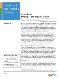
interfaces. The former is for the MSS flash disk, and the latter is for connecting other hardware components. The design of host to hardware device interconnection is based on two rationales. First, in a device like our smart dispenser, the data rate between the host and each hardware device is very low. For this reason, we make all hardware devices, except the MSS disk, share the same RS232 connection. Second, hardware devices in the dispenser do not support RS232 interface. An agent that supports RS232 is needed to facilitate communication for all devices and manage their data transmissions to and from the host. The agent is the microcontroller unit as shown in Figure 3. The microcontroller forwards commands issued by the device driver of each hardware device to the device, and the device driver abstracts low-level instructions of the device into general driver functions. In general, drivers of hardware components provide the dispenser controller with two kinds of facilities: hardware control and event notification. The former consists of commands which the controller can call to request services from hardware components. The latter is the primary means of communication from hardware to controller. As an example, Part (a) of Figure 4 shows the logic diagram of a binary sensor array (BSA), which in the case of the dispenser, implements the array of switches illustrated by part (b) of the figure. The BSA driver provides a command to reset all switches and clear the array, as well as the bit map used to indicate the current states of all switches. It communicates with the dispenser controller via three event objects: OBJECT_IN, OBJECT_OUT and STATE_CHANGE. The driver sets the event OBJECT_IN (or OBJECT_OUT)
when the switch in a socket changes state from 0 to 1 (or 1 to 0) indicating that a container is just plugged in (or removed from) the socket. In response the controller calls the handler GetPluggedInSocket() (or GetPluggedOutSocket()) to get the index (i.e., location) and current
state of the socket. The driver sets STATE_CHANGE event when more than one switch change state. The controller can determine the switches involves and their current states by invoking the function GetSensorStates (char* Buffer) to get the bit map.
14
Similarly, the controller can command the RFID reader to read tags on the containers by calling Event ReadTags (char* Buffer, &Status, Timeout). When invoked, the function returns a completion event immediately while the device driver commands the RFID reader to read in non-addressed mode. When read completes, the driver sets the completion event. The controller usually goes to wait for the completion event soon after it issues a read-tag command. When it wakes up by the event, it can determine from the returned status whether the read operation succeeded and, if the operation succeeded, the ids of tags read and returned by the reader driver. Switch (binary sensor)
Microcontroller int
Socket
ack
data Bit map
Serialize Output IC Output 1
2
RFID Reader FF
FF
FF
15
PTD
Binary sensors FF = D Flip-Flop
(b) (a) Figure 4 Binary Sensor Array
The reminder used by the dispenser may be a sophisticated device or a simple one. The prototype uses an audio device capable of playing different tones or voice messages to indicate the urgency of the reminder. Its driver provides control functions ReminderOn (int urgency) and ReminderOff () for turning the device on and off, and when turned on, play different tones (or
voice messages) depending on the urgency of the reminder. Finally, the driver of the PTD button provides no command function. It communicates with the controller via two event objects, one for pressing down the button and the other for releasing the button. 5 Action-Oriented Collaboration As stated earlier, the controller and the scheduler collaborate in an action-oriented manner. By an action, we mean an atomic unit of work carried out by an action handler function (or simply, 15
action handler). Actions may be prioritized. Their action handlers are executed as work items by worker threads at the priorities of the actions. Figure 5 shows the operation cycle of a collaborative process based on the action-oriented model in general. Each of the collaborative entities plays one of two roles: decision maker or action executor. There may be more than one action executor. For obvious reasons, there should be either only one decision maker, or a group of entities jointly serves as one decision maker. In our smart dispenser prototype, the dispenser controller is the one and only action executor, the medication scheduler is the decision maker. Decision maker (Medication Scheduler) Request
Query
Report
action(s) Specify NHST
next action(s) action complete
NHST arrives or Action completed Workers carrying out actions
Work dispatcher
Action Executor (Dispenser Controller)
Figure 5 Action-oriented collaboration
5.1 Decision Maker Interface We adopt here the variant of the model where the executor plays a purely passive role. It is only time keeper in the system. While it is aware of the time, it relies completely on the decision maker to specify the time instants for it to query for actions, the actions it is to execute at those instants, and so on. We call the nearest future time instant at which the decision maker requests the executor to query for actions the next hand shake time (NHST). When given a NHST, the executor sets a timer to expire at that time, waits until then to query the decision maker for action. In response, the decision maker may request new action(s) to be executed, provides the executor with a new NHST, and thus enables the repetition of the operation cycle. 16
Table 2 lists the basic API functions provided by the interface of the component serving as the decision maker, which is referred to as the DM in the table to save space. The functions SetInformation ( ) and GetInformation ( ) allow the caller to deliver and get various types of
information to and from the decision maker. Table 2 Decision-Maker API functions
Void SetInformation (InformationType, InformationData): This function allows the executor to deliver information to the DM. InformationType gives the type of data structure containing the information to be delivered. InformationData supplies a pointer to the data structure holding the information to be delivered. Void GetInformation (InformationType, InformationData): This function allows the caller to get information from the DM. Parameters are of the same types as those of SetInformation ( ) except that they are for data to be returned from the DM. ActionDescription GetNextAction (SystemTime CurrentTime): This function allows the caller to query the DM for actions to be performed by the caller. CurrentTime provides the current system time. The function returns a pointer to a structure of type ActionDescription {ActionList, NextHandShakeTime} ActionDescription ActionComplete (ActionType, ActionResult): This function allows the caller to notify the DM that the specified action is completed. ActionType specifies the type of completed action. ActionResult provides a pointer to result of the completed action. Void EventNotify (EventType, EventParameters) This function allows the caller to notify the DM of occurrences of an event of a specified type. EventType specifies the type of event. EventParameters supplies a pointer to parameters that the DM needs to decide how to handle the event.
The work horse is GetNextAction (CurrentTime). By calling this function, the executor queries the decision maker for the actions to carry out, while informing the decision maker of the current time. GetNextAction ( ) always returns a future time, called the next handshake time (NHST). It also returns an action description. The action description structure contains an action list. The value of the field is NULL when the decision maker requests no action; otherwise, it is the head of a list of ActionItem structures. Each action item structure specifies an action to be executed: Specifically, the fields of each ActionItem structure include the name of an action and a pointer to parameters to be passed to the action handler, and the priority of the action. The structure also contains a Report flag, which indicates whether the result produced by the action is to be returned to the decision maker, and a pointer to the location for the returned result. 17
The executor calls ActionComplete ( ) to report the completion of a specified action and to deliver the result produced by the action. The function also serves as a query for next actions as it also returns an action description and NHST. The executor is also the component in the system that monitors all events in the system that warrants attention. It can call the API function EventNotify() to inform the decision maker of occurrences of events that the decision maker needs to participate in handling. The executor calls GetNextAction() immediately after it calls EventNotify() so that actions the decision maker wants
to be carried out in response to the event(s) are handled promptly. 5.2 Communication Flow Figure 6 illustrates the protocol governing the communication between the executor and the decision maker. It also illustrates how the functions GetNextAction() and ActionComplete() are used to support their communication.
Set timer to expire at t_1 Queue work items
Executor
Decision Maker GetNextAction() Action List 1
Report action complete
NHST = t_1 ActionComplete() Action List 2
timer to expire at t_2 Queue work item for new action
NHST = t_2
Set
t_1
GetNextAction()
t_2
Action List 3 NHST = t_3
Figure 6 Executor-decision-maker communication
In the timing diagram, time flows downward. The exchange between the components starts from a call of GetNextAction( ) by the executor. When the function returns, the executor first sets the NHST timer to expire at the time (say t_1) given by the value of NHST returned by the function, along with an action list. When the action list is not NULL, the executor creates a work 18
item for each action in the list and queues the item for execution at the priority of the action. We will return in the next section to describe how this is done by the dispenser controller. Suppose that one of the actions completes before t_1, and the action result is supposed to be returned to the decision maker. The executor calls ActionComplete() to report action complete and to deliver the result. The figure shows the case where the decision maker decides to request a new action and specifies a later NHST of t_2. The executor, therefore, resets the timer to expire at t_2, and creates and queues a work item for the new action. Now, suppose that all the pending actions remain incomplete when the timer expires at t_2. Since t_2 is the appointed time for the executor to query for action again, the executor does so as requested by the decision maker. The figure shows the case where the action list returned at the time is NULL. So, the executor queues no work item, but reset the NHST timer to t_3. 6 Controller and Scheduler Collaboration Again, when applied the action-oriented model to our smart dispenser, the medication scheduler is the decision maker and dispenser controller is the sole executor. We have found that this division of labor simplifies the design and implementation of both components. In particular, having the controller to be the only time keeper makes ordering actions in time, as the dispenser often needs to do, straightforward. The design also relieves the medication scheduler from the need to monitor time and external events. It now only needs to provide the API functions listed in Table 2 and works when its API functions are called. 6.1 Controller Software Structure Figure 7 shows the control structure of the prototype dispenser controller and its connection with the medication scheduler. The controller relies on an extensible library of action handler functions to carry out actions. By adding and exporting new handler functions to the library, a developer can make the dispenser capable of new actions or enhanced versions of existing
19
actions with little or no change to the control structure of the controller. Medication Scheduler MSS
Medication Record
Medication timetable Next handshake time Events or Results
GetNextAction()
Actions
Dispenser Controller Work item dispatcher
Action handler dynamic link library
Work queues Monitor threads Thread pool
Figure 7 Dispenser controller structure
The majority of actions done during normal operation of the dispenser are for medication administration purpose. These actions are requested by the scheduler in manner illustrated by Figure 6. The dispenser controller also initiates actions in response to occurrence of events indicating conditions that warrant attention. Each action is assigned a priority by the component that requests the action. Whenever possible, executions of action handlers on the CPU are scheduled preemptively according to priorities of the actions. 1) Work Queues and Worker Threads The structure of the controller is based on a variation of the well known leader/follower pattern [28]. During initialization, the controller (main) thread creates several FIFO work queues of different priorities and a pool of worker threads. Work items inserted into each queue are processed by worker threads at the priority of the queue. One of the responsibilities of the controller thread is to serve as the work item dispatcher. When the dispatcher gets one or more actions from the scheduler or initiates actions on its own, it looks up the action handler functions that carry out the actions and the priorities of the actions. It wraps the pointer to each function in an instance of WorkItem data structure, along with 20
pointers to a structure of function parameters and where result is to be returned. The WorkItem structure also includes the Report flag, which the dispatcher sets to the value provided by the Report field of the corresponding action item. The dispatcher then inserts the work item into one
of the queues according to the priority of the corresponding action. Upon finishing its duty as a dispatcher, the controller thread returns to wait for the completion of the actions and other events that require its attention. At any time, each of the work queues is monitored by a work thread, called the monitor thread of the queue in Figure 7. When the thread finds work item(s) in the queue, it removes the one at the head of the queue. Because the execution of the work item may take some time, the monitor thread wakes up a worker thread in the pool to serve as the monitor thread of the queue and then call the action handler function pointed to by the work item. When the function returns, the thread notifies the controller thread that the work has been completed and returns to wait in the thread pool. If the Report flag is set, the controller thread returns the result produced by the action handler function to the medication scheduler. 2) Event Notification The controller uses events to notify the medication scheduler of conditions that requires attention of the scheduler, as illustrated by Figure 7. Examples include that the PTD button is pressed. In response, the scheduler checks the existing medication schedule and makes adjustment in dose size(s) if needed. Like controllers of typical smart devices, the dispenser controller is also responsible for monitoring all device conditions. In addition to general conditions (e.g., power on/off), dispenser-specific conditions monitored by sensors include the ones concerning medication supplies, MSS and BSA. The sensor threads within the controller set events when the supply in some container is running low, the MSS flash disk has been plugged in and MSS file read and some container has been plugged in or removed. The events used for this purpose are MedicationInsufficient, MSSChanged, and BSAStatusChanged, respectively. The occurrences of
21
the conditions signaled by these events may warrant that the user be alerted, the medication schedule be re-computed, and sometimes even a professional care taker to be alerted, and so on. The controller uses the scheduler API function EventNotify( ) to notify the medication scheduler whenever it cannot handle the event without the assistance of the scheduler. 6.2 Illustrative Example To illustrate the collaboration between the controller and the scheduler in action-oriented manner, as well as how the dispenser works to prevent serious medication administration error, we consider a simple example in which the user takes 20 mg of vitamin once daily and 10 mg of insulin every 4 hours. Without loss of generality, suppose that the dispenser is set up prior to 8:00 o’clock. According to the schedule computed by the medication scheduler immediately after set up operation completes, the user is to take the daily dose of vitamin at 8:00 and 10 mg doses of insulin at 9:00, 13:00, 17:00, and so on. Vitamin, being a supplement, can be skipped with little or no consequence. In contrast, doses of insulin cannot be skipped arbitrarily. Its direction says: 1. When the user is tardy for more than 4 hours, the pending dose is cancelled, and a double-size dose of 20 mg is scheduled at the next dose time. 2. Contact the user’s doctor if the user has not taken insulin for 10 hours or more. We note that the relaxation from a dose every 4 hour schedule allowed by the first rule permits the user to have 8 hours for uninterrupted sleep. The second rule defines a non-compliant event and intends to prevent serious omission error. Figure 8 shows the interaction between the controller and the scheduler. Again, time flows downwards and is not drawn in scale. Part (a) of the figure illustrates the case when the user responds promptly to reminder and retrieves a scheduled dose on time. Part (b) illustrates what happens when the user is tardy to the extent that the dispenser has to handle a non-compliance event. The wiggly lines at the left edge of each part represent running worker threads: The fat and short one turns the reminder on or off; the long and thin one monitors user response and 22
helps the user retrieve a dose, and widely wiggly one handles the non-compliance event. The operation starts from the controller making a GetNextAction( ) call in part (a). In response, the scheduler requests no action, only asked to be queried again at 8:00 o’clock, the dose time for vitamin. The controller sets the NHST timer to expire at 8:00 and goes to wait: Controller Controller
Scheduler 13:00
Scheduler
GetNextAction()
GetNextAction()
Action list: 1.SetAlarm (on, persistence = 1) 2.SetUserResponse(on) 3. *DoseAfterResponse (insulin = 10mg)
NHST = 8:00
o n
8:00
GetNextAction()
NHST = 17:00
Action list: 1.SetAlarm (on, persistence = 0) 2.SetUserResponse(on) 3. * DoseAfterResponse (vitamins = 20mg)
o n
17:00
GetNextAction()
ActionComplete()
NHST = 17:00
NHST = 9:00 8:10
Action list: 1. *DoseAfterResponse (insulin = 20mg)
ActionComplete() Dose time = 8:10 Action list: 1.SetAlarm (off, persistence = 0) 2.SetUserResponse(off)
o f f
Action list: 1. *CancelDose
NHST = 19:00
19:00
GetNextAction()
NHST = 9:00
Action list: 1. *Call doctor NHST = 8:00
9:00
GetNextAction()
(b) (a) Figure 8 An illustrative example z
At 8:00 when the NHST timer expires, the controller queries the scheduler for action, telling the scheduler that the current time is 8:00 o’clock. The NHST = 9:00 returned by the scheduler is the next dose time for insulin. The action list returned by the scheduler specifies three actions: The SetAlarm (on, 0) action turns on the reminder. Since vitamin may be skipped, the scheduler sets the persistence parameter to 0, telling the controller that the reminder can be turned off automatically after a brief interval of time. The second and third actions in the list starts the controller to monitor the PTD button and when the user responds by pushing the button, dispense 20 mg of vitamin as described in the Section 3.1. 23
To safe space in the figure, we put a “*” in front of an action name to indicate that the scheduler wants the result of the action return. After queuing work items for the actions, the controller sets the NHST timer to expire at 9:00 and returns to wait for the timer. z
Suppose the user responds to the reminder and push the PTD button at 8:10, while the reminder is still on. The controller helps the user retrieves from the vitamin container a 20 mg tablet and then calls ActionComplete( ) to return the actual dose time of 8:10. As this function is also a query for the next action, the scheduler returns two actions: They turn off the reminder and stop monitoring the PTD button. After these actions are dispatched, the controller goes to wait for the NHST timer to expire at 9:00.
z
Suppose that all went well prior to 13:00. In particular, the user promptly retrieved the 9:00 dose of insulin. In response to the GetNextAction() call from the controller at 13:00, the scheduler requests that the reminder be turned on, this time persistently until the scheduler requests for it to be turned off. Then the controller is to start monitoring the PTD button and prepared to help the user retrieve a 10 mg dose of insulin when the user pushes the button. After it dispatched the work items for these actions, the controller sets the NHST timer to expire at 17:00 and goes to wait.
z
At 17:00, the user still has not responded. When the controller calls GetNextAction(), the scheduler can determine from the fact that the controller has not yet reported the completion of the DoseAfterResponse action it requested at 13:00, the dose scheduled at that time is still pending. Moreover 4 hours has elapsed. The schedule needs to be adjusted. Hence, the scheduler requests that the pending dose be cancelled, while it consults the medication schedule specification and adjusts the schedule. When the controller reports the completion of CancelDose, the scheduler requests that a 20 mg dose is to be given to the user when the user responds. There is no need for turning on the reminder because it is still on, and the controller is still monitoring the PTD button. The value of NHST returned by
24
the scheduler this time is 19:00. By then, 10 hours will have been elapsed since the user took the latest dose of insulin. If the user still has not come to push the PTD button by 19:00, the scheduler will request that the controller calls the designated care taker to report the non-compliance event. The value of NHST is 8:00, the time for dose of vitamin for the next day. In the meantime the 20 mg dose of insulin is still pending. 7 Heuristic Scheduling Algorithms This section provides an overview of the algorithms [27] for scheduling multiple medications. The algorithms work with fixed dose sizes. As stated earlier, that a valid dose size exists has already been assured when the user’s MSS was generated. By first choosing a valid dose size for each medication, the scheduler then focuses on finding times for individual doses to meet all intra-medication and inter-medication separation constraints. 7.1 Underlying Model The design of the scheduler is based on the resource model [26, 27] that uses a virtual processor PM and a virtual resource RM for each medication M to keep track of when the user is available to take the medication. When computing a schedule, the scheduler treats each dose of each medication M as if it is a job on processor PM and the sequence of doses of the medication as a task M. A job starts when the corresponding dose should be retrieved by the user. A schedule for the medication is a list of the time instants at which jobs of task M start. Figure 9 shows the data structures used by the scheduler. Part 1 holds values of constraints parameters of each medication. In addition, the scheduler maintains integer arrays processor and resource for each medication M. The initial values of all elements of the arrays are 0, indicating that PM and RM are free. When it schedules a job of M on the virtual processor (or allocates the resource to the job) at time k since the start of the schedule, the scheduler sets the value of the k-th element of the corresponding array to 1, indicating that the processor (or the resource) is occupied.
25
Part 1: Internal data structures for information on each medication Class MedicationDirections{ int med_id; DosageParameters dp; SpecialInstructions si; } Class DosageParameters{ int t_min, t_max; int ns_min, ns_max, as_min, as_max; int nd_min, nd_max, ad_min, ad_max; int b, r, l, p; } Class SpecialInstructions{ List drug_and_food_interaction; List change_lists; } Class Interferer{ int med_id; int min_to_interferer; int min_fr_interferer; } Part 2: Resource model data structures for each medication Class ResourceModel{ int[] resource = new int[t_min]; int[] processor = new int[t_min]; bool feasible = TRUE; List schedule = NULL; int priority = 0; } Class JobModel{ int release_time = 0; int execution_time = ns_min; int deadline = release_time + execution_time; } Part 3: Data structure of priority schemes enum PrioritySchemes{ RM, MVF, MIF, SSDF, EDF};
Figure 9 Data structure for medication M
1) Processor Scheduling and Resource Allocation Rules The scheduler uses an instance of the structure JobModel to hold the parameters of jobs of each medication M. The execution_time field of the structure is initially set to the nominal minimum separation smin(M) of M. The scheduler maintains correct separations between doses of M by scheduling each of the corresponding jobs non-preemptively on PM for this amount of time whenever possible, but it may schedule the job for a smaller amount time in the range from the absolute minimum separation Smin(M) of M to smin(M). In addition, the maximum absolute separation between consecutive doses of M is enforced by imposing a relative deadline for each of the jobs. For each medication M that has interferers, the scheduler uses the virtual resource RM and resources of the interferers to help it maintain inter-medication separations. Simply put, a job of M can start at a time t only when the resource RM is free at t. The scheduler allocates the resource RM to each job of N for σmin(N, M) units of time each time when it schedules a job on PN. Thus, each job of the interferer blocks jobs of M from starting for this amount of time. The worst-case 26
blocking time of the medication M is the maximum over all of its interferers of the minimum separations from interferer to M. 2) Priority Schemes Again, both OMAT and ODAT algorithms use priorities. As we will see shortly, one of the better priority schemes is the Most Victimized First (MVF) scheme which gives priorities to tasks based on their worst case blocking times; the longer the worst case blocking time, the higher the priority. Other priority schemes based on separation and interference characteristics of the medications include the Most Interferers First (MIF) scheme and the Shortest Separation Difference First (SSDF) schemes. They give higher priorities to tasks corresponding to medications with larger numbers of interferers or larger differences between the maximum and minimum nominal separations, respectively. We also experimented with the classical real-time priority schemes Rate Monotonic (RM) and Earliest Deadline First (EDF) schemes. The former gives higher priorities to tasks with shorter periods. The latter gives priorities to jobs based on their absolute deadlines; the earlier the deadline, the higher the priority. Clearly, EDF scheme is suitable for ODAT algorithms only. 7.2 Algorithm Descriptions Figure 10 gives pseudo-code descriptions of basic versions of OMAT and ODAT algorithms. The inputs are MedicationDirections of all medications in a MSS and PrioritySchemes used by the algorithm. The value of the Boolean output variable feasible indicates whether the algorithm succeeded in finding a feasible schedule when it terminates. If it succeeded (i.e., feasible is TRUE), the elements of the feasible_schedule [ ] array point to the schedules (i.e., lists of job
start time instants) of all medication in the MSS. 1) OMAT Algorithms. After creating instances of data structures described above, the scheduler considers medications in non-increasing priority order: It schedules jobs (i.e., doses) of each medication M one at time, starting from the first job until it either fails to find an available
27
(start) time for some job of M before the minimum duration t_min of the medication or has successfully generated a list of start times for all the jobs within the duration. (An available time for a job is an instant between the release time and deadline of the job at which both PM and RM are free. The search for the earliest of such instants and the bookkeeping chores of the scheduler are described by Step 3 in part (a) of the figure.) In the former case, the scheduler returns immediately, with feasible set to FALSE. In the latter case, it sets the element in feasible_schedule [ ] for the medication to point to the newly generated list and then move on to
work on the medication next in priority order. Input: List MSS, PrioritySchemes;
Input: List MSS, PrioritySchemes;
Output : feasible = TRUE; feasible_schedule [number_medications] = {NULL};
Output : feasible = TRUE; feasible_schedule [number_medications]= {NULL};
1. For every medication listed in MSS, create an instance of JobModel, ResourceModel and list head schedule. 2. Assign priority to each medication according to PrioritySchemes. 3. For each medication Mi from the one with the highest priority to lowest, do the following: latest_start_time = 0; current_medication_feasible = TRUE; do while ( current_medication_feasible == TRUE ) { A. Call FindAvailableTime ( ) to get the earliest available time instant x B. if x is found, if ( x >= t_min of Mi ) break; Insert x into the start time list schedule of Mi for ( x