SIS Programming and Control The MLS 608 D units can be remotely controlled via a host computer or other device (such as an optional MLC 226 control system) attached to the rear panel RS-232 connector or the front panel USB configuration port. The device can be configured and controlled by the Extron Simple Instruction Set (SIS™) of commands or by using the Extron DSP Configurator software program. This section describes SIS communication and control. Topics that are covered include: zz
Host to MLS 608 D Communications
zz
Command and Responses
The switcher uses a default protocol of • 38400 baud • 1 stop bit • no parity • no flow control.
Host to MLS 608 D Communications SIS commands consist of one or more characters per field. No special characters are required to begin or end a command sequence. When the MLS 608 D switcher determines that a command is valid, it executes the command and sends a response to the host device. All responses from the switcher to the host end with a carriage return and a line feed (CR/LF = ]), signalling the end of the response character string (one or more characters).
MLS 608 D Switcher-initiated Messages When a local event occurs, such as a front panel operation, the MLS 608 D responds by sending a message to the host. The MLS 608 D-initiated messages are listed below. Boot-up messages (c) Copyright 2011, Extron Electronics, MLS 608 D xx, Vx.xx, 60-1050-0x ] The copyright message is initiated by the switcher when it is first powered on. Vx.xx is the firmware version number. Status change messages The switcher-initiated status change messages are a result of front panel operations (actual or software-simulated). The status change messages are the same as switcher responses to certain commands. See the last column of the command/response tables on the following pages.
MLS 608 D Series • SIS Communication and Control
23
Error Responses When the switcher receives a valid command, it executes the command and sends a response to the host device. If the unit is unable to execute the command because the command contains invalid parameters, it returns an error response to the host.
Error Numbers zz
E01 — Invalid input number
zz
E10 — Invalid command
zz
E11 — Invalid preset number
zz
E12 — Invalid port number
zz
E13 — Invalid parameter
zz
E14 — Not valid for this configuration
zz
E17 — Invalid command for signal type
zz
E22 — Busy
zz
E24 — Privilege violation
Error Response References 14
= Commands that give an E14 (invalid command for this configuration) error if sent to a product whose current configuration does not support the command
24
= Commands that give an E24 (privilege violation) error if not administrator level
Command and Responses Using the Command/response Tables The following pages of commands can be sent to the MLS 608 D via the Extron Data Viewer (available free at www.extron.com) and connected via the front panel mini USB config port, or via the rear panel RS-232 port using HyperTerminal.
The command/response table for SIS commands later in this chapter lists the commands that the MLS 608 D switcher recognizes as valid, the responses that are returned to the host, a description of each command function or the results of executing the command, and an example of each command in ASCII and URL encoded. NOTE:
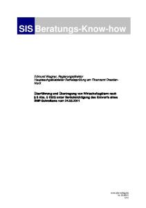
Upper and lower case text can be used interchangeably except where noted. ASCII to HEX Conversion Table Space •
Figure 9.
ASCII to Hexadecimal Character Conversion Table MLS 608 D Series • SIS Communication and Control
24
Symbol definitions • = Space ] = Carriage return with line feed } = Carriage return with no line feed E = Escape = Superscripts indicate the error message displayed if the command is entered incorrectly or with invalid parameters. See the “Error Response References” section.
14, 24, 22, 27, 28
X! = Input number (0-8). 0 = no connection X@ = Analog input (1 through 3) X# = Input video format, 1 = composite, 2 = S-video, 3 = YUV, 4 = RGB (all sync formats) X$ = RGB delay for inputs for 1 through 3, maximum delay is 5 seconds, in 0.5 second steps, 0 = 0 seconds, 1 = 0.5 seconds,... 10 = 5 seconds X% = Audio mute, 0 = no mute, 1 = mute X^ = Group number, 1-32 (Group 1 is reserved for the program volume encoder. 2 is for mic volume encoder. 3 is for bass control. 4 is for treble control. 5 is for output volume mute.) X& = Increment and decrement dB values, in 0.1 dB steps (multiply dB by 10, so 10 = 1.0 dB)
MLS 608 D Series • SIS Communication and Control
25
X* = Master volume value, 0 to -100 dB, in 0.1 dB steps, for example 0 = 0 dB, -1 = -0.1 dB, -10 = -1.0 dB, -100 = -10 dB, -1000 = -100 dB, see table below. Master volume values, X* = (SIS value) dB value
SIS value
% Output volume
dB value
SIS value
% Output volume
dB value
SIS value
% Output volume
dB value
SIS value
% Output volume
0
0
100
-21.0
-210
79.0
-51.0
-510
49.0
-81.0
-810
19.0
-0.1
-1
99.9
-22.0
-220
78.0
-52.0
-520
48.0
-82.0
-820
18.0
-0.2
-2
99.8
-23.0
-230
77.0
-53.0
-530
47.0
-83.0
-830
17.0
-0.3
-3
99.7
-24.0
-240
76.0
-54.0
-540
46.0
-84.0
-840
16.0
-0.4
-4
99.6
-25.0
-250
75.0
-55.0
-550
45.0
-85.0
-850
15.0
-0.5
-5
99.5
-26.0
-260
74.0
-56.0
-560
44.0
-86.0
-860
14.0
-0.6
-6
99.4
-27.0
-270
73.0
-57.0
-570
43.0
-87.0
-870
13.0
-0.7
-7
99.3
-28.0
-280
72.0
-58.0
-580
42.0
-88.0
-880
12.0
-0.8
-8
99.2
-29.0
-290
71.0
-59.0
-590
41.0
-89.0
-890
11.0
-0.9
-9
99.1
-30.0
-300
70.0
-60.0
-600
40.0
-90.0
-800
10.0
-1.0
-10
99.0
-31.0
-310
69.0
-61.0
-610
39.0
-91.0
-910
9.0
-2.0
-20
98.0
-32.0
-320
68.0
-62.0
-620
38.0
-92.0
-920
8.0
-3.0
-30
97.0
-33.0
-330
67.0
-63.0
-630
37.0
-93.0
-930
7.0
-4.0
-40
96.0
-34.0
-340
66.0
-64.0
-640
36.0
-94.0
-940
6.0
-5.0
-50
95.0
-35.0
-350
65.0
-65.0
-650
35.0
-95.0
-950
5.0
-6.0
-60
94.0
-36.0
-360
64.0
-66.0
-660
34.0
-96.0
-960
4.0
-7.0
-70
93.0
-37.0
-370
63.0
-67.0
-670
33.0
-97.0
-970
3.0
-8.0
-80
92.0
-38.0
-380
62.0
-68.0
-680
32.0
-98.0
-980
2.0
-9.0
-90
91.0
-39.0
-390
61.0
-69.0
-690
31.0
-99.0
-990
1.0
-10.0
-100
90.0
-40.0
-400
60.0
-70.0
-700
30.0
-100.0
-1000
0
-11.0
-110
89.0
-41.0
-410
59.0
-71.0
-710
29.0
-12.0
-120
88.0
-42.0
-420
58.0
-72.0
-720
28.0
-13.0
-130
87.0
-43.0
-430
57.0
-73.0
-730
27.0
-14.0
-140
86.0
-44.0
-440
56.0
-74.0
-740
26.0
-15.0
-150
85.0
-45.0
-450
55.0
-75.0
-750
25.0
-16.0
-160
84.0
-46.0
-460
54.0
-76.0
-760
24.0
-17.0
-170
83.0
-47.0
-470
53.0
-77.0
-770
23.0
-18.0
-180
82.0
-48.0
-480
52.0
-78.0
-780
22.0
-19.0
-190
81.0
-49.0
-490
51.0
-79.0
-790
21.0
-20.0
-200
80.0
-50.0
-500
50.0
-80.0
-800
20.0
X( = Group member OID numbers X1) = Values for inputs 5 through 8, 5 = 30008, 6 = 30010, 7 = 30012, 8 = 30014 X1! = Audio format, 0 = analog, 1 = digital (default) X1@ = Preset number, 1 through 8. MLS 608 D Series • SIS Communication and Control
26
X1# = Mic number (mute inputs), 40000 = Mic 1, 40001 = Mic 2 X1$ = Inputs 1-10, 1-8 = program audio inputs, 9 = Mic 1 audio input, 10 = Mic 2 audio input. X1% = Output number, 1 through 4 X1^ = Input signal peaking adjustment range, 0-255 X1& = Skew adjustment value, user range 0-31, in 2 ns increments (for example 31 = 62 ns) X1* = Video plane, 0 = red, 1 = green, 2 = blue X1( = Input signal level adjustment range, 0-255 (default = 60). X2) = Output bass/treble master value (240 to -240, default = 0), multiplied dB by 10. (for example 230 = +23 dB, -210 = -21 dB) X2! = DDC value (EDID). See table below.
SIS Variables for EDID Resolution/Refresh Rate Combination (where X2! = 1 through 52) Digital Signal Resolution
Refresh Rate Hz
Automatic Mode (Digital only)
Analog Signal SIS value for X2!
SIS value for X2!
Resolution
Refresh Rate Hz
0
800x600
60
29
800x600
60
1
1024x768
60
30
1024x768
60
2
1280x768
60
31
1280x768
60
3
1280x800
60
32
1280x800
60
4
1280x1024
60
33
1280x1024
60
5
1360x768
60
34
1360x768
60
6
1366x768
60
35
1366x768
60
7
1440x900
60
36
1440x900
60
8
1400x1050
60
37
1400x1050
60
9
1600x1200
60
38
1600x1200
60
10
1680x1050
60
39
1680x1050
60
11
1920x1200
60
40
1920x1200
60
12
576p
50
41
576p, 2-ch PCM Audio
50
13
480p
60
42
480p, 2-ch PCM Audio
60
14
720p
50
43
576p, Multi-ch Audio
50
15
720p
60
44
480p, Multi-ch Audio
60
16
1080i
50
45
720p, 2-ch PCM Audio
50
17
1080i
60
46
720p, 2-ch PCM Audio
60
18
1080p
50
47
720p, Multi-ch Audio
50
19
1080p
60
48
720p, Multi-ch Audio
60
20
User Loaded #1
49
1080i, 2-ch PCM Audio
50
21
User Loaded #2
50
1080i, 2-ch PCM Audio
60
22
1080i, Multi-ch Audio
50
23
1080i, Multi-ch Audio
60
24
1080p, 2-ch PCM Audio
50
25
1080p, 2-ch PCM Audio
60
26
1080p, Multi-ch Audio
50
27
1080p, Multi-ch Audio
60
28
User Loaded #3
51
User Loaded #4
52
MLS 608 D Series • SIS Communication and Control
27
X2@ = Video group, 1 = VGA, 2 = HDMI X2# = Output selection, 1 = analog buffered VGA output on MLS 608 D, 2 = digital HDMI output on MTP/HDMI U R. X2$ = Analog EDID user definable locations, 49 = user 1, 50 = user 2. X2% = Digital EDID user definable locations, 51 = user 3, 52 = user 4. X2^ = EDID, 0 = current assigned EDID, 1 = user loaded 49 when X2@ = 1, user loaded 51 when X2@ = 2, 2 = user loaded 50 when X2@ = 1, user loaded 52 when X2@ = 2 X2& = 128 or 256 byte EDID raw HEX (text form) X2* = Native resolution and refresh rate response, for example 1280x720@60 X2( = Inputs 5 through 8 only (for HDCP commands) X3) = Output selection -1 X3! = Input HDCP status, 0 = source connected but not HDCP compliant. 1 = source connected and is HDCP compliant. 2 = no source connected. 3 = HDCP status not known X3@ = Output HDCP status, 0 = output connected, current input source encrypted, output is not HDCP compliant. 1 = output connected, current input source encrypted, output is HDCP compliant. 2 = no output connected. 3 = output connected, current input source is not encrypted or not connected, output HDCP status not known X3# = HDCP notification = green screen notification on the output when a source is non-HDCP compliant, 0 = black, 1 = green (default) X3$ = Power save mode, 0 = off (default), 1 = on X3% = Firmware version number (x.xx). X3& = Device part number. 60-1050-01 = MLS 608 D 60-1050-02 = MLS 608 D MA 60-1050-03 = MLS 608 D SA X3* = MLS 608 D, or MLS 608 D MA, or MLS 608 D SA X3( = Video signal status, 0 = video /TMDS not detected, 1 = video /TMDS detected, - = unknown. X4) = Voltage in volts (V) X4! = Temperature in degrees C, response is three digits with leading zero (for example 31°C = 031 ). X4@ = Audio mute to DSP, 0 = audio unmuted, 1 = audio muted X4# = Executive mode (front panel lock), 0 = off (all unlocked -default), 1 = lockout all (input buttons and encoders), 2 = lockout input buttons only X4$ = Baud rate, 300, 600, 1200, 1800, 2400, 3600, 4800, 7200, 9600, 28800, 38400 (default), 57600, 115200 X4% = Parity, Odd, Even, None (default), Mark, Space, (only use first letter, for example N = None) X4^ = Data bits, 7, 8 (default = 8) X4& = Stop bits, 1, 2 (default = 1)
MLS 608 D Series • SIS Communication and Control
28
X4* = Verbose mode, 0 = no verbose mode and non-tagged responses for queries, 1 = verbose mode and non-tagged responses for queries (default), 2 = no verbose and tagged responses for queries, 3 = verbose mode and tagged responses for queries X4( = Mute status, 0 = mute off, 1 = mute on (default). X5) = Mute value, +00000 = off, +00001 = on (default). X5! = Mic number, 40100 = Mic 1, 40101 = Mic 2. X5@ = Mic gain value, 0 to -100 dB, in 0.1 dB steps. For example 2048 = 0 dB, 2047 = -0.1 dB, 2038 = -1 dB, 1948 = -10 dB, 1048 = -100 dB. See table below. Mic Gain Master Values, X5@ = (SIS value) dB value
SIS value
% volume
dB value
SIS value
% volume
dB value
SIS value
% volume
dB value
SIS value
% volume
0
2048
100
-21.0
1838
79.0
-51.0
1538
49.0
-81.0
1238
19.0
-0.1
2047
99.9
-22.0
1828
78.0
-52.0
1528
48.0
-82.0
1228
18.0
-0.2
2046
99.8
-23.0
1818
77.0
-53.0
1518
47.0
-83.0
1218
17.0
-0.3
2045
99.7
-24.0
1808
76.0
-54.0
1508
46.0
-84.0
1208
16.0
-0.4
2044
99.6
-25.0
1798
75.0
-55.0
1498
45.0
-85.0
1198
15.0
-0.5
2043
99.5
-26.0
1788
74.0
-56.0
1488
44.0
-86.0
1188
14.0
-0.6
2042
99.4
-27.0
1778
73.0
-57.0
1478
43.0
-87.0
1178
13.0
-0.7
2041
99.3
-28.0
1768
72.0
-58.0
1468
42.0
-88.0
1168
12.0
-0.8
2040
99.2
-29.0
1758
71.0
-59.0
1458
41.0
-89.0
1158
11.0
-0.9
2039
99.1
-30.0
1748
70.0
-60.0
1448
40.0
-90.0
1148
10.0
-1.0
2038
99.0
-31.0
1738
69.0
-61.0
1438
39.0
-91.0
1138
9.0
-2.0
2028
98.0
-32.0
1728
68.0
-62.0
1428
38.0
-92.0
1128
8.0
-3.0
2018
97.0
-33.0
1718
67.0
-63.0
1418
37.0
-93.0
1118
7.0
-4.0
2008
96.0
-34.0
1708
66.0
-64.0
1408
36.0
-94.0
1108
6.0
-5.0
1998
95.0
-35.0
1698
65.0
-65.0
1398
35.0
-95.0
1098
5.0
-6.0
1988
94.0
-36.0
1688
64.0
-66.0
1388
34.0
-96.0
1088
4.0
-7.0
1978
93.0
-37.0
1678
63.0
-67.0
1378
33.0
-97.0
1078
3.0
-8.0
1968
92.0
-38.0
1668
62.0
-68.0
1368
32.0
-98.0
1068
2.0
-9.0
1958
91.0
-39.0
1658
61.0
-69.0
1358
31.0
-99.0
1058
1.0
-10.0
1948
90.0
-40.0
1648
60.0
-70.0
1348
30.0
-100.0
1048
0
-11.0
1938
89.0
-41.0
1638
59.0
-71.0
1338
29.0
-12.0
1928
88.0
-42.0
1628
58.0
-72.0
1328
28.0
-13.0
1918
87.0
-43.0
1618
57.0
-73.0
1318
27.0
-14.0
1908
86.0
-44.0
1608
56.0
-74.0
1308
26.0
-15.0
1898
85.0
-45.0
1598
55.0
-75.0
1298
25.0
-16.0
1888
84.0
-46.0
1588
54.0
-76.0
1288
24.0
-17.0
1878
83.0
-47.0
1578
53.0
-77.0
1278
23.0
-18.0
1868
82.0
-48.0
1568
52.0
-78.0
1268
22.0
-19.0
1858
81.0
-49.0
1558
51.0
-79.0
1258
21.0
-20.0
1848
80.0
-50.0
1548
50.0
-80.0
1248
20.0
MLS 608 D Series • SIS Communication and Control
29
Command Response Table for SIS Commands Command
ASCII Command (host to switcher)
Response
(switcher to host)
Additional Description
Input Selection Select video and audio input
X!!
ChnX!]
Select an video and audio input source X!
View current input
!
X!]
View current selected input source X!.
Select a video input
X!&
VidX!]
Select a video only input source X!.
View current video input
&
X!]
View currently selected video input source X!.
Select an audio input
X!$
AudX!]
Select an audio only input source X!.
View current audio input
$
X!]
View currently selected audio input source X!.
Video Configuration Set analog video format
X@*X#\
InpX@•Typ=X#]
Set input X@ to X#.
View video format
X@ \
X#]
View video format X# for analog input X@.
Video Mute (Output) NOTE:
Mutes all video: composite, s-video, component, RGB and digital (TMDS).
Video mute
1B
Vmt 1]
Mute video outputs.
Video unmute
0B
Vmt 0]
Unmute video outputs.
View mute status
B
0 or 1]
View mute status.
HDMI Audio Mute (Output) NOTE:
Mutes the embedded audio on the HDMI output.
Audio mute
1Z
Amt 1]
Mute audio output.
Audio unmute
0Z
Amt 0]
Unmute audio output.
View mute status
Z
0 or 1]
View output mute status.
Mic Input Mute NOTE:
This command controls the first gain block of the mic input. See the DSP Configurator Help file for details.
Set mic input mute
EMX1#*X4(AU}
DsMX1#*X4(]
Set the mic input mute X4( for mic X1#.
View master value
EMX1#AU}
X4(]
View master value X4(.
NOTE:
X! = Input selection, 0 through 8, 0 = no connection X@ = Analog input, 1 through 3 X# = Input video format, 1= composite, 2 = S-video, 3= YUV, 4 = RGB (all sync formats), default = RGB X1# = Mic number (mute inputs), 40000 = Mic 1, 40001 = Mic 2 X4( = Mute status, 0 = mute off, 1 = mute on (default)
MLS 608 D Series • SIS Communication and Control
30
Command
ASCII Command (host to switcher)
Response
(switcher to host)
Additional Description
Mic Gain Control NOTE:
This command controls the gain blocks immediately after the ducker blocks. See the DSP Configurator Help file for details.
Set Mic gain
EGX5!*X5@AU}
DsGX5!*X5@]
Set the Mic gain X5@ for Mic X5!
View master value
EGX5!AU}
X5@]
View master value X5@.
GrpmDX^*X*]
Set the gain value X* for group number X^.
Set Group Master Value Set gain (dB)
NOTE:
EDX^*X*GRPM}
Reserved groups are: 1 = Program volume, 2 = Mic volume, 3 = Output Bass, 4 = Output treble, 5 = Output volume mute.
Audio mute or unmute
EDX^*X%GRPM}
GrpmDX^*X%]
Mute or unmute X% for group number X^.
Increment gain
EDX^*X&+GRPM}
GrpmDX^*X&]
Increase the gain value by X& for group number X^.
Decrement gain
EDX^*X&-GRPM}
GrpmDX^*X&]
Decrease the gain value by X& for group number X^.
View master value
EDX^GRPM}
X*]
View group master value X*.
View group members numbers
EOX^GRPM}
X(1*X(2*X(3* X(4....*X(16
View group member OID numbers.
ED1*X*GRPM}
GrpmD01*X*]
Set the gain value X* for group master 1.
Example: ED1*0GRPM}
GrpmD01*+00000]
Sets the gain value to 0 dB.
Example: ED1*-100GRPM}
GrpmD01*-00100]
Sets the gain value to -10 dB.
Example: ED1*-1000GRPM}
GrpmD01*-01000]
Sets the gain value to -100 dB.
Increment gain
ED1*X&+GRPM}
GrpmD01*X*]
Increase the gain value X* by X&.
Decrement gain
ED1*X&-GRPM}
GrpmD01*X*]
Decrease the gain value X* by X&.
View master value
ED1GRPM}
X*]
View the current master value X*.
Program Volume (Group Master 1) Set gain (dB)
NOTE:
X% X^ X& X*
= Audio mute; 0 = no mute, 1 = mute = Group master number, 1 through 32, groups 1 through 5 are reserved groups, see note above. = Increment and decrement dB values, in 0.1 dB steps (multiply dB by 10, for example 10 = 1.0 dB). = Master volume value, 0 to -100 dB, in 0.1 dB steps, for example 0 = 0 dB, for example 0 = 0 dB, -1 = -0.1 dB, -10 = -1.0 dB, -100 = -10 dB, -1000 = -100 dB, see gain table on page 26 for details. X( = Group member OID number X5! = Mic number, 40100 = Mic 1, 40101 = Mic 2 X5@ = Mic gain value, 0 to -100 dB, in 0.1 dB steps, for example 2048 = 0 dB, 2047 = -0.1 dB, 2038 = -1 dB, 1048 = -10 dB, 1048 = -100 dB, see gain table on page 29 for details.
MLS 608 D Series • SIS Communication and Control
31
Command
ASCII Command (host to switcher)
Response
(switcher to host)
Additional Description
Mic Volume (Group Master 2) ED2*X*GRPM}
GrpmD02*X*]
Set the gain value X* for group master 2.
Example: ED2*0GRPM}
GrpmD02*+00000]
Sets the gain value to 0 dB
Example: ED2*-100GRPM}
GrpmD02*-00100]
Sets the gain value to -10 dB
Example: ED2*-1000GRPM}
GrpmD02*-01000]
Sets the gain value to -100 dB
Increment Gain
ED2*X&+GRPM}
GrpmD02*X*]
Increase the gain value X* by X&.
Decrement Gain
ED2*X&-GRPM}
GrpmD02*X*]
Decrease the gain value X* by X& .
View master value
ED2GRPM}
X*]
View master value X*.
ED3*X2)GRPM}
GrpmD03*X2)]
Set the gain value X2) for group master 3.
Example: ED3*240GRPM}
GrpmD03*+00240]
Sets the gain value to +24 dB.
Example: ED3*0GRPM}
GrpmD03*+00000]
Sets the gain value to 0 dB.
Example: ED3*-100GRPM}
GrpmD03*-00100]
Sets the gain value to -10 dB.
Increment gain
ED3*X&+GRPM}
GrpmD03*X2)]
Increase the gain value X2) by X&.
Decrement gain
ED3*X&-GRPM}
GrpmD03*X2)]
Decrease the gain value X2) by X&.
View master value
ED3GRPM}
X2)]
View master value X2).
ED4*X2)GRPM}
GrpmD04*X2)]
Set the gain value X2) for group master 4.
Example: ED4*240GRPM}
GrpmD04*+00240]
Sets the gain value to +24 dB.
Example: ED4*0GRPM}
GrpmD04*+00000]
Sets the gain value to 0 dB.
Example: ED4*-100GRPM}
GrpmD04*-00100]
Sets the gain value to -10 dB.
Increment gain
ED4*X&+GRPM}
GrpmD04*X2)]
Increase the gain value X2) by X&.
Decrement gain
ED4*X&-GRPM}
GrpmD04*X2)]
Decrease the gain value X2) by X&.
View master value
ED4GRPM}
X2)]
View master value X2).
Set gain (dB)
Output Bass Adjust (Group Master 3) Set gain (dB)
Output Treble Adjust (Group Master 4) Set gain (dB)
NOTE:
X& = Increment and decrement dB values, in 0.1 dB steps (multiply by 10, for example 10 = 1.0 dB). X* = Master volume value, 0 to -100 dB, in 0.1 dB steps, for example 0 = 0 dB, -1 = -0.1 dB, -10 = -1.0 dB, -100 = -10 dB, -1000 = -100 dB, see gain table on page 26 for details. X2) = Output bass/treble master value (240 to -240, default 0), decibel value multiplied by 10. (for example 230 = +23 dB, -210 = -21 dB)
MLS 608 D Series • SIS Communication and Control
32
Command
ASCII Command (host to switcher)
Response
(switcher to host)
Additional Description
Overall Output Volume Mute Adjustment (Group Master 5) NOTE:
This command mutes the program and mic audio. It does not mute the embedded audio on the HDMI output signal.
Set volume mute
ED5*X4(GRPM}
GrpmD05*X4(]
Set the volume mute X4( for group master 5.
View master value
ED5GRPM}
X5)]
View master value X5).
Audio Input Format NOTE:
For audio inputs 5-8. Selects between analog (5-pole captive screw) or digital (embedded in HDMI input).
Set format
EDX1)*X1!AU}
X1!]
Sets audio input X1) to format X1!.
View format
EDX1)AU}
X1!]
View audio format X1! for input X1).
RGB Delay Time NOTE:
RGB delay affects only inputs 1-3 and if configured to RGB format.
Set RGB delay
EX$D}
DlyX$]
Set RGB delay to (X$ x 0.5) seconds.
View setting
ED}
X$]
View RGB delay setting.
Set output pre-peak on
E1Opek}
Opek1]
Turn output pre-peak on.
Set output pre-peak off
E0Opek}
Opek0]
Turn output pre-peak off (default).
View
EOpek}
1] or 0]
View status.
MTP Output Pre-peak
MTP Input Signal Level Adjustment Specify a value
EX1(ILVL}
IlvlX1(]
Specify an input signal level value X1(.
Increment value
E+ILVL}
IlvlX1(]
Increase the signal level value by 1.
Decrement gain
E-ILVL}
IlvlX1(]
Decrease the signal level value by 1.
View current value
EILVL}
X1(]
View current level X1(.
NOTE:
X$ = RGB delay for inputs 1 through 3, maximum delay is 5 seconds, in 0.5 second intervals, default = 0 seconds X1) = Values for inputs 5 through 8, 5 = 30008, 6 = 30010, 7 = 30012, 8 = 30014 X1! = Audio format, 0 = analog, 1 = digital (default setting) X1( = Input signal level adjustment range, 0 to 255, (default = 60) X4( = Mute status, 0 = mute off, 1 = mute on (default) X5) = Mute value, +00000 = off, +00001 = on (default)
MLS 608 D Series • SIS Communication and Control
33
Command
ASCII Command (host to switcher)
Response
(switcher to host)
Additional Description
MTP Input Signal Peaking Adjustment Specify a value
EX1^IPEK}
IpekX1^]
Specify an input peaking value X1^.
Increment value
E+IPEK}
IpekX1^]
Increase value by 1.
Decrement gain
E-IPEK}
IpekX1^]
Decrease value by 1.
View current value
EIPEK}
X1^]
View current X1^.
Input Skew Adjustment Set input skew values
EX1&*X1&*X1&ISEQ}
IseqX1&*X1&*X1&]
Set input skew values X1& for R, G, and B signals (IseqR*G*B).
Increment one input skew value
EX1*+ISEQ}
IseqX1&*X1&*X1&]
Increase the skew value of X1* by 1.
Decrement one input skew value
EX1*-ISEQ}
IseqX1&*X1&*X1&]
Decrease the skew value of X1* by 1.
View current value
EISEQ}
X1&*X1&*X1&]
View skew value.
Output Skew Adjustment Set output skew values
EX1&*X1&*X1&OSEQ}
OseqX1&*X1&*X1&]
Set output skew values X1& for R, G, and B signals (OseqR*G*B).
Increment one output skew value
EX1*+OSEQ}
OseqX1&*X1&*X1&]
Increase the skew value of X1* by 1.
Decrement one output skew value
EX1*-OSEQ}
OseqX1&*X1&*X1&]
Decrease the skew value of X1* by 1.
View current value
EOSEQ}
X1&*X1&*X1&]
View skew value.
X1@.
RprX1@]
Recall preset X1@ .
View preset video tie
EX1@*1*1VC}
X!•Vid]
View the video input X! tied as a preset.
View preset audio tie
EX1@*1*2VC}
X!•Aud]
View the audio input X! tied as a preset.
Recall Presets Recall preset
View Preset Ties
NOTE:
X! = Input selection, 0 through 8, 0 = no connection X1@ = Preset number, 1 through 8 X1^ = Input signal peaking adjustment range, 0 to 255 (default = 0) X1& = Skew adjustment value, user range 0-31, in 2 ns increments (for example 31 = 62 ns) X1* = Video plane, 0 = red, 1 = green, 2 = blue
MLS 608 D Series • SIS Communication and Control
34
Command
ASCII Command (host to switcher)
Response
(switcher to host)
Additional Description
Naming Presets Write preset name
EX1@,nameNG}
NmgX1@,name]
Name preset X1@.
Read preset name
EX1@NG}
name]
View name X1@ .
NOTE:
• If preset unassigned, name displays [unassigned]. • If preset is saved but not yet named, default is “Preset X1@”(where X1@ is the preset number). • If user tries to name when preset is unassigned, unit responds with E11. • If user tries to recall an unsaved preset, unit responds with E11. • Invalid characters: ~ , @ = ‘ [ ] { } < > ” ; :| \ and ?.
Write input name
EX1$,nameNI}
NmiX1$,name]
Name input X1$.
Read input name
EX1$NI}
name]
View input X1$ name.
Write output name
EX1%,nameNO}
NmoX1%,name]
Name output X1%.
Read output name
EX1%NO]
name]
View output X1% name.
Assign EDID data to inputs (analog and digital inputs)
EAX2@*X2!EDID}
EdidAX2@*X2!]
Assign EDID data X2! to inputs VGA or HDMI X2@
View EDID data assigned
EAX2@EDID}
X2!]
View EDID data assignment.
Save an output EDID to (analog) user loaded space
ESX2#*X2$EDID}
EdidSX2#*X2$]
Save display EDID to analog user space.
Save an output EDID to (digital) user loaded space
ESX2#*X2%EDID}
EdidSX2#*X2%]
Save display EDID to digital user space.
View/read EDID in Hex format
ERX2@EDID}
X2&]
View EDID data in Hex format for X2@.
View EDID native resolution
ENX2@*X2^EDID}
X2*]
View native resolution and refresh rate.
EDID Management
NOTE:
X1@ = Preset number, 1 through 8 X1$ = Inputs 1 through 8; 1-8 = program audio inputs, 9 = Mic 1 audio input, 10 = Mic 2 audio input X1% = Output number, 1 through 4 X2! = DDC value (EDID). See table on page 27 for details. X2@ = Video group, 1 = VGA, 2 = HDMI X2# = Output selection, 1 = analog buffered VGA connector on MLS 608 D, 2 = digital HDMI connector on MTP/HDMI U R X2$ = Analog EDID user definable locations , 49 = user 1, 50 = user 2 X2% = Digital EDID user definable locations , 51 = user 3, 52 = user 4 X2^ = EDID, 0 = current assigned EDID, 1 = user loaded 49 when X2@ = 1, user loaded 51 when X2@ = 2; 2 = user loaded 50 when X2@ = 1, user loaded 52 when X2@ = 2 X2& = 128 or 256 Byte EDID raw HEX (text form) X2* = Native resolution and refresh rate, for example 1280x720@60
MLS 608 D Series • SIS Communication and Control
35
Command
ASCII Command (host to switcher)
Response
(switcher to host)
Additional Description
HDCP View input HDCP status
EIX2(HDCP}
X3!]
Signal present, HDCP, non HDCP, or HDCP status unknown.
View output HDCP
EOHDCP}
X3@]
Output connected, HDCP, non HDCP, or HDCP status unknown.
View HDCP for all HDMI inputs
EI*HDCP}
X3!5*X3!6*X3!7*X3!8]
HDCP, non HDCP, or HDCP status unknown (for all HDMI inputs).
Set HDCP notification
ENX3#HDCP}
X3#]
Show green or black screen.
View HDCP notification
ENHDCP}
X3#]
Turn power save off
E0PSAV}
PsavX3$]
Turn power save on
E1PSAV}
PsavX3$]
View power save
EPSAV}
X3$]
Power Save Mode
View power save status.
Front panel security lockout (Executive Mode) Enable Executive mode 1
1X
Exe1]
Lock out front panel buttons and knobs.
Enable Executive mode 2
2X
Exe2]
Lock out front panel buttons only.
Disable Executive mode
0X
Exe0]
Unlock all front panel controls.
View Executive mode status
X
0 ] (or) 1 ] (or) 2 ]
View the current status: 0 = off [default]; 1 = on, lock all buttons and knobs; 2 = on, lock input buttons only.
NOTE:
X2( = Inputs 5 through 8 only (for HDCP commands) X3! = Input HDCP status, 0 = source is connected but not HDCP compliant, 1 = source is connected and is HDCP compliant, 2 = no source connected, 3 = HDCP status not known X3@ = Output HDCP status, 0 = output is connected, current input source encrypted, output is not HDCP compliant, 1 = output is connected, current input source encrypted, output is HDCP compliant, 2 = no output connected, 3 = output is connected, current input source is not encrypted or not connected, output HDCP status not known X3# = HDCP notification = green screen notification on the output when a display is non-HDCP compliant, 0 = black, 1 = green (default) X3$ = Power save mode, 0 = off (default), 1 = on
MLS 608 D Series • SIS Communication and Control
36
Command
ASCII Command (host to switcher)
Response
(switcher to host)
Additional Description
Information Requests Query firmware version
Q or 1Q
x.xx]
View the firmware version.
Query part number
N
X3&]
View the part number X3&.
Query AV input
I
VidX!•AudX!]
View current AV input.
Query model name
1I
X3*]
View model name X3*.
View video signal presence
LS
X3(*X3(*X3(*X3(*X3(*X3(*X3( *X3(]
Shows signal presence for all inputs, 1-8.
View +1.5V FPGA voltage
15S}
+X4)]
View Internal Temp in °C
20S}
+X4!]
View audio mute to DSP
40S}
X4@]
Reset (Zap)/Erase Commands Reset all video and audio settings to factory default
EZXXX]
Zpx]
Resets all video and audio settings.
Reset all settings to factory default
EZQQQ]
Zpq]
Resets all video and audio settings, protected, configuration, verbose mode, and control port settings.
Delete all presets and names
EZG]
Zpg]
Removes all presets and preset names.
Delete individual preset
EX1@ZG]
ZpgX1@]
Removes a selected preset.
Bi-directional Serial Port Commands Configure parameters24
E1*X4$,X4%,X4^,X4& CP}
Cpn01X4$,X4%,X4^,X4&]
Set baud rate X4$, parity X4%, data bits X4^, and stop bits X4&.
View parameters
E1CP}
X4$,X4%,X4^,X4&]
View baud rate X4$, parity X4%, data bits X4^, and stop bits X4&.
Verbose settings Set verbose mode
EX4*CV]
VrbX4*]
Set verbose mode parameters.
View parameters
ECV]
X4*]
View verbose mode parameters.
NOTE:
X! = Input selection, 0 through 8, 0 = no connection X1@ = Preset number, 1 through 8 X3& = Device part number. 60-1050-01 = MLS 608 D, 60-1050-02 = MLS 608 D MA, 60-1050-03 = MLS 608 D SA X3* = MLS 608 D, or MLS 608 D MA, or MLS 608 D SA X3( = Video signal status, 0 = video /TMDS not detected, 1 = video /TMDS detected, - = unknown X4) = Voltage in volts (V) X4! = Temperature in degrees C, response is three digits with leading zeros (for example 031 = 31°C) X4@ = Audio mute to DSP, 0 = audio unmuted, 1 = audio muted X4$ = Baud rate, 300, 600, 1200, 1800, 2400, 3600, 4800, 7200, 9600, 28800, 38400 (default), 57600, 115200 X4% = Parity, Odd, Even, None (default), Mark, Space, (only use first letter, for example N = None) X4^ = Data bits, 7, 8 (default = 8) X4& = Stop bits, 1, 2 (default = 1) X4* = Verbose mode: 0 = no verbose mode and non-tagged responses for queries, 1 = verbose mode and non-tagged responses for queries (default), 2 = no verbose and tagged responses for queries, 3 = verbose mode and tagged responses for queries
MLS 608 D Series • SIS Communication and Control
37