2016 20th International Conference on System Theory, Control and Computing (ICSTCC), October 13-15, Sinaia, Romania
Simulation Environment for Mobile Robots Testing Using ROS and Gazebo Kenta Takaya∗ , Toshinori Asai† , Valeri Kroumov‡ and Florentin Smarandache§ ∗ Graduate
School, Okayama University of Science, 1-1 Ridai-cho, Okayama City 700–0005, Japan Email:
[email protected] † FBR Technology Engineering Services Co., 2-2-2 Chuo-cho, Tsuruga City 914-0811, Japan Email:
[email protected] ‡ Dept. of Electrical & Electronic Engineering, Okayama University of Science, 1-1 Ridai-cho, Okayama City 700-0005, Japan Email:
[email protected] § University of New Mexico, 705 Gurley Ave., Gallup, New Mexico 87301, USA Email:
[email protected] Abstract—In the process of development a control strategy for mobile robots, simulation is important for testing the software components, robot behavior and control algorithms in different surrounding environments. In this paper we introduce a simulation environment for mobile robots based on ROS and Gazebo. We show that after properly creating the robot models under Gazebo, the code developed for the simulation process can be directly implemented in the real robot without modifications. In this paper autonomous navigation tasks and 3D-mapping simulation using control programs under ROS are presented. Both the simulation and experimental results agree very well and show the usability of the developed environment. Index Terms—Mobile robot simulation, 3D mapping, ROS, Gazebo.
I. I NTRODUCTION Today’s robot system is a complex hardware device equipped with a numerous sensors and computers which are often controlled by complex distributed software. Robots must navigate and perform successfully specific tasks in various environments and under changing conditions. However, it is costly and time consuming to build different test fields and to examine the robot behaviour under multiple conditions. Using a well-developed simulation environment allows safe and costeffective testing of the robotic system under development. The simulation decreases the development cycle and can be versatilely applied for different environments. Even though there exist several software platforms (cf. Section II) for simulation and robot control, as far as the authors are concerned, ROS (Robot Operation System)[1] allows building of reliable robot control and navigation software and Gazebo[2] simulation together with ROS’s RVis library helps to create simulation, which results can be directly deployed to the real robot hardware. In this paper we describe the design and implementation of an environment for development and simulation of mobile robots using ROS and Gazebo software. Accurate models of the simulated robots and their working environment are designed. Simulation and experiments for mapping and control c 978-1-5090-2720-0/16/$31.00 2016 IEEE
are presented as well. The contribution of this paper is: (a) the content of the paper can be used as a tutorial for building 2D and 3D environment simulation models under Gazebo and simulation of robot models in those environments; (b) an effective method for creating precise 3D maps by suitable combination of the ROS packages is presented. The software used during simulations is successfully used in the control of real robots without any modifications. The final goal of this research is a development of reliable guiding robot for elderly or disabled people for indoor and outdoor environments. At present, differential drive robots are considered because they can move and turn in narrow places and are enough manoeuvrable compared to other types wheeled robots. This paper is organized as follows. The next section describes related work. Section III describes briefly Gazebo and the ROS software. The robot and the working environment models are introduced there, too. Section IV and Section V detail the 2D and 3D simulation and experimental results, respectively. In Section VI the simulation and experimental results are analyzed and compared to other work and plans for further developments are presented. Section VII concludes the paper. II. R ELATED W ORK There are several commercial and open source simulation environments for robotic field. Some common examples of such software are briefly listed here. WEBOTS[3] supports C/C++, Java, Python, URBI and MATLAB and has TCP/IP interface to communicate to other software products. It has many components which can be connected to create complex construction easily. Visual Components[4] is a simulation suite for production lines and can even simulate entire factory. Robot Virtual Worlds[5] was primarily designed for educational purpose but it seems that it can be used for some advanced applications. LabVIEW[6] is a complex software system suited for data acquisition, analysis, control, and automation. It has numerous libraries
96
for simulation of hardware components and supports most of the standard interfaces. On other hand there exist a great number of open source simulators and many of them have very advanced features. USARSim (Unified System for Automation and Robot Simulation)[7] is commonly used in RoboCup rescue virtual robot competition as well as a research platform. It is based on the Unreal Tournament Game Engine[8]. Initially, the Unreal Engine was proprietary, but starting from 2015, it is available for free. The OpenHRP3[9] (Open-architecture Human-centered Robotics Platform version 3) is compatible with OpenRTMaist[10]—a robotic technology middleware. However, the OpenHRP is designed to develop and simulate mainly humanoid robots. There are some attempts[11] to develop a software supporting the OpenRTM-aist for simulation of other types of robots, as well. OpenRAVE[12] is a tool for testing, development, and simulation for robotics systems. It uses high level scripting such as MATLAB and Octave. The OpenRAVE focuses mainly on humanoid robots and robot manipulators. However, it has ROS plugins that create Nodes (executables) for controllers and sensors data simulation. A comparison between several open source simulation environments for mobile robots can be found in [13], [14] and the references there. There are many publications about robot simulation covering variety of robots: manipulators, legged robots, underwater vehicles, and unmanned aerial vehicles (UAV). Many of those developments are based on ROS and Gazebo software packages which proves their reliability and great usability. The Virtual Robotics Challenge[15] hosted by Defense Advanced Research Projects Agency (DARPA) as a part of the DARPA Robotics Challenge led to development and improvement of simulation software to run nearly identically to the real robotic hardware[16]. Simulation of manipulation tasks including grasp and place motions are presented in [17]. The advantages and disadvantages of simulators for testing the robot behaviours are compared in [18]. Results in UAV simulation and experimental challenges are covered in other publications[19], [20]. III. ROBOT S IMULATION U NDER ROS AND G AZEBO A. Gazebo Gazebo is a part of the Player Project[21] and allows simulation of robotic and sensors applications in three-dimensional indoor and outdoor environments. It has a Client/Server architecture and has a topic-based Publish/Subscribe model of interprocess communication. Gazebo has a standard Player interface and additionally has an native interface. The Gazebo clients can access its data through a shared memory. Each simulation object in Gazebo can be associated with one or more controllers that process commands for controlling the object and generate the state of that object. The data generated by the controllers are published into the shared memory using Gazebo interfaces (Ifaces). The Ifaces of other processes can read the data from the shared
memory, thus allowing interprocess communication between the robot controlling software and Gazebo, independently of the programming language or the computer hardware platform. In the process of dynamic simulation Gazebo can access the high-performance physics engines like Open Dynamics Engine (ODE)[22], Bullet[23], Simbody[24] and Dynamic Animation and Robotics Toolkit (DART)[25] which are used for rigid body physical simulation. Object-Oriented Graphics Rendering Engine (OGRE)[26] provides the 3D graphics rendering of environments of Gazebo. The Client sends control data, simulated objects’ coordinates to the Server which performs the real-time control of the simulated robot. It is possible to realize a distributed simulation by placing the Client and the Server on different machines. Deploying ROS Plugin for Gazebo helps to implement a direct communication interface to ROS, thus controlling the simulated and the real robots using the same software. This provides an effective simulation tool for testing and development of real robotic systems. B. ROS ROS[1] is a collection of libraries, drivers, and tools for effective development and building of a robot systems. It has a Linux-like command tool, interprocess communication system, and numerous application-related packages. The ROS executable process is called Node and interprocess communication has a Publish/Subscribe model. The communication data is called Topic. The Publisher process may publish one or more Topics and processes which subscribe to certain Topic can receive its content. The interprocess communication library allows easily to add user developed libraries and ROS executables. Moreover, the ROS-based software is language and platform-independent—it is implemented in C++, Python, and LISP. Furthermore, it has experimental libraries in Java and Lua[1]. The process name resolving and execution is scheduled by the Master Server. The ROS packages include many sensor drivers, navigation tools, environment mapping, path planning, interprocess communication visualization tool, as well as a 3D environment visualization tool and many others. ROS allows effective development of new robotic systems and when used together with a simulation middleware like Gazebo the time for development a reliable and high performance robotic control software can be dramatically decreased. C. Robot and Environment Modeling In representing the robot and environment models in ROS, the URDF (Universal Robotic Description Format) is used. The URDF is an XML file format used and standardized in ROS for description of all elements (sensors, joints, links etc.) of a robot model. Because URDF can only specify the kinematic and dynamic properties of a single robot in isolation, to make the URDF file work properly in Gazebo, additional simulation-specific tags concerning the robot pose, frictions, inertial elements and other properties were added[27]. The addition of these properties makes the original URDF file
97
... plugin parameters ... (a) The URDF file
... plugin parameters ... (b) The SDF file Fig. 1. Using gazebo plugins.
compatible with the native SDF (Simulation Description Format) Gazebo’s model description format. The SDF can fully describe the simulated world together with the complete robot model. The process of conversion from URDF to SDF can be easily done by adding the so called gazebo plugins into URDF file. The gazebo plugins can attach into ROS messages and service calls the sensor outputs and driving motor inputs[28], i.e. the gazebo plugins create a complete interface (Topic) between ROS and Gazebo. The control process intercommunication under ROS is achieved by performing a Publish/Subscribe to that Topic. There are several plugins available in gazebo plugins[28]: Camera (ROS interface for simulating cameras), Multicamera (synchronizes multiple camera shutters to publish their images together—typically stereo cameras), GPU Laser, F3D (for external forces on a body), Inertial Measurement Unit (IMU), Bumper, Differential Drive, Skid Steering Drive, Planar Move Plugin and many others. Fig. 1
Fig. 3. P3-DX and lab models in Gazebo
shows the result of conversion of an URDF to SDF format. For the purpose of this study we have created models of PeopleBot and Pioneer 3-DX robots. The model of P3-DX is distributed together with Gazebo, but its dimensions and properties differ from the real robot. Because of this a new much more precise model of P3-DX including the models of several sensors was created. Part of P3-DX model was adopted in the process of designing the PeopleBot model. The models of 2D (Hokuyo UTM-30LX LIDAR) and 3D (Hokuyo YVT-X002 LIDAR) laser finders, sonars, odometry, camera, IR sensors, and bumpers were also added. Additionally, the robots masses and frictions were properly defined. The created models of both robots are shown in Fig. 2. In the process of simulation we are using the already distributed Willow Garage model and the model of one of our laboratories as shown in Fig. 3. IV. 2D S IMULATION AND E XPERIMENTAL R ESULTS
Fig. 2. Pioneer3-DX (left) and PeopleBot (right) models in Gazebo.
This section describes the simulation results using ROS and Gazebo. The robot model and the real robot are equipped with 2D laser finder (Hokuyo UTM-30LX LIDAR), 2 Web cameras (Logicool c615), sonars (16pcs for P3-DX robot and 24psc for PeopleBot), odometry system and a laptop computer for controlling the robot. The sonars are used by the obstacle avoidance Node. Because there is no a plugin for sonars
98
Fig. 4. Map generation using Hector mapping in Rviz Fig. 5. Navigation using AMCL in RViz
in the gazebo plugins, we adopted the Laser plugin (ray, libgazebo ros laser.so) making it work approximately like a sonar sensor. Additionally, we have designed an obstacle avoidance Node: a standard Britenberg vehicle type node. The first camera is used for environment monitoring and the second one transfers the floor area directly in front of the robot which increases the reliability during remote control operations. The robot and the environment models are created using Gazebo and simulation is performed under the ROS control. As depicted in Fig. 4 and Fig. 5 the simulation results are visualized using the RViz package. By using the Camera plugin the simulated environment is displayed in RViz (left side in the figures). The goal position of the robot is set by pointing and clicking at it with the computer mouse. The simulation results from map generation of unknown environment and robot navigation using the generated map are presented in the next subsections. For path generation we are using the ROS Navigation Stack[29] package which extensively uses costmap[30] to store information about the obstacles situated in the robot working space and builds occupancy grid of the data. The Navigation Stack uses one costmap for global planning and another one for local planning and obstacle avoidance. The global planning is based on the Dijkstra’s Algorithm[31] and in the local coordinates the path is additionally corrected using Dynamic Window Approach (DWA)[32]. A. Unknown Environment Mapping Simulation A simulation example of map generation of unknown environment is shown in Fig. 4. To perform map generation the hector mapping[33] package was used. hector mapping realizes the SLAM (Simultaneous Localization and Mapping) algorithm and provides robot pose estimates at the scan rate of the laser scanner (40Hz for the UTM-30LX LIDAR). Generally, the package does not need odometry if the robot platform does not perform yaw motion. Because during the simulations our obstacle avoidance algorithm causes some yaw motions, we are using the odomery data to properly estimate the robot pose. One way to perform the map generation is by simultaneously setting goal positions until the whole working space is covered by the robot. Another approach is to make the robot to “explore” the environment until the complete map
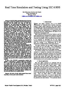
is constructed. The problem with the latter is that a special care must be taken in the exploration algorithm to make the robot not to perform unnecessary turns and “reexplore” already covered areas. Otherwise, the map generation process may take very long time. In our simulations we are using the first approach: setting simultaneously goals as depicted in Fig. 4. Fig. 5 shows the completed map which is further used in the navigation simulation. B. Navigation Simulation After performing the map generation using the hector mapping package, we used the amcl[34] (Adaptive Monte Carlo Localization) package for navigation inside the generated map. To properly estimate the robot position inside the environment, this package uses the laser scan and odometry readings data as well a laser-based map. Most of the algorithms used by amcl package are described in [35]. One simulation result in known environment is shown in Fig. 5. C. Experimental Results Using the simulation control software we performed experiments of control of real robots under ROS. During the experiments there was no difference in robots behaviour compared to the simulations. However, due to differences in the interprocess communication speed and calculation speeds there was need to tune some parameter of the Navigation stack node. V. 3D M APPING S IMULATION AND E XPERIMENTAL R ESULTS To perform the 3D mapping we use the Octomap package[36] and the Hokuyo YVT-X002 LIDAR model. The Octomap Package does not possess a SLAM algorithm and relies on odometry measurements, which introduce a bias in the position estimation of the robot and consequently uncertainties in the map as shown in Fig. 6. In order to solve the above problem we have combined the Octomap and the Hector Mapping as follows. Instead to use the 3D laser Topic for the YVT-X002, we changed it with 2D Topic to create a map using the Hector Mapping Package (SLAM algorithm). While using the robot position from the 2D SLAM we create the 3D map by Octomap, and combining
99
VI. D ISCUSSION
Fig. 6. 3D Mapping Using Only the Octomap Package
Fig. 7. 3D Mapping Using Octomap and Hector Mapping
the 2D and 3D maps we performed the visualization under RViz tool. These tasks are performed in parallel without doing additional scans of the environment. The result is generation of quite precise 3D map as shown in Fig. 7 and 8. Fig. 7 depicts an experimental result under ROS control and Fig. 8 shows the simulation using Gazebo. From the figures it can be confirmed that the maps are precise enough. The map created during the experiment has some noise which successfully can be neglected.
2D and 3D real-time mapping and simulations cause very high load on the CPUs. The laptop computers used R CoreTM i5– in the course of the experiments were Intel
[email protected] equipped with 8GB RAM. During the experiments the robot speed was set to 0.4 [m/s] and the whole map building and navigation run smootly, while due to the extensive calculations during the simulation, the robot speed had to be decreased to about 0.2 [m/s]. The ROS and Gazebo software run under 64-bit Ubuntu 15.04 OS. Even though there exist several software platforms (cf. Section II) for simulation and robot control, as far as the authors are concerned, ROS allows building of reliable robot control and navigation software and Gazebo simulation together with ROS’s RVis library helps to create simulation, which results can be directly deployed to the real robot hardware. During the robot navigation it is very much important to perform precise localization and position correction of the mobile robot. The authors have already proposed a method for localization and position correction using artificial landmarks(see R [38] algo[37] and the references there) based on vSLAM rithm. That method has very good performance for indoor environments but the map building based on vSLAM does not work well for outdoor applications and it is almost impossible to render realistic 3D maps[39]. In this work, to perform reliable outdoor and indoor navigation, a map building using laser sensors and dead reckoning was adopted. VII. C ONCLUSION The purpose of this study is to develop a reliable environment for simulation and control of mobile robots using the ROS and Gazebo software. It was shown that after designing properly the models of the robot platforms and their working environments the software used in the simulations can be directly used to control the real robots. Simulations and experimental results in 2D and 3D mapped environments prove the usability of the models. The main contribution of this paper is that the well done combination of ROS packages allowed real-time generation of precise map in 3D space. The paper describes in details which software packages were employed and we hope that the results reported here will be useful at least for part of the roboticists community. The final goal of this research is a design of reliable guiding robot for elderly for indoor and outdoor environments. We are in process of deploying a voice recognition and voice synthesis for Japanese and after adding a face recognition functions we will be able to realize the next stage of the project. ACKNOWLEDGMENT
Fig. 8. 3D Map Generation Using Gazebo in RViz (simulation)
The authors would like to thank Mr. Hirona Kato for his valuable support during the experiments. This work was partially supported by the Japanese Ministry of Education, Culture, Sports and Technology (MEXT): Strategic Research on QOL Innovation 2012–2016.
100
R EFERENCES [1] Open Source Robotic Foundation. (2016) ROS/Introduction. [Online]. Available: http://wiki.ros.org/ROS/Introduction [2] (2016) Robot simulation made easy. [Online]. Available: http:// gazebosim.org/ [3] (2016) Webots. [Online]. Available: https://www.cyberbotics.com [4] (2016) Visual Components. [Online]. Available: http://www. visualcomponents.com/products/ [5] (2016) Robot Virtual Worlds. [Online]. Available: http://www. robotvirtualworlds.com/ [6] National Instruments. (2016) What Can You Do With LabVIEW? [Online]. Available: http://www.ni.com/labview/why/ [7] S. Carpin, M. Lewis, J. Wang, S. Balakirski, and C. Scrapper, “USARSim: a robot simulator for research and education,” in Proc. 2007 IEEE International Conference on Robotics and Automation, Roma, Italy, April 2007, pp. 1400–1405. [8] Epic Games. (2016) Unreal Engine 4. [Online]. Available: https://www. epicgames.com/ [9] OpenHRP3 Official Site (2016) About OpenHRP3. [Online]. Available: http://fkanehiro.github.io/openhrp3-doc/en/about.html [10] Japan’s National Institute of Advanced Industrial Science and Technology. (2016) OpenRTM-aist. [Online]. Available: http://www.openrtm. org/openrtm/en/node/629 [11] I. Chen, B. MacDonald, B. Wunsche, G. Biggs, and T. Kotoku, “A Simulation Environment for OpenRTM-aist,” in Proc. SII 2009. IEEE/SICE International Symposium on System Integration, Tokyo, Japan, Nov. 2009, pp.113–117. [12] R. Diankov and J. Kuffner, “Openrave: A planning architecture for autonomous robotics,” Robotics Institute, Pittsburgh, PA, Tech. Rep. CMU-RI-TR-08-34, July 2008. [13] P. Castillo-Pizarro, T.V. Arredondo, and M. Torres-Torriti, “Introductory Survey to Open-Source Mobile Robot Simulation Software,” in Proc. 2010 Latin American Robotics Symposium and Intelligent Robotics Meeting (LARS), 2019, pp. 150–155. [14] D. Cook, A. Vardy, and R. Lewis, “A survey of AUV and robot simulators for multi-vehicle operations,” in Proc. 2014 IEEE/OES Autonomous Underwater Vehicles (AUV), Ocford, Missisippi, Oct. 2014, pp. 1–8. [15] Defense Advanced Research Projects Agency (DARPA). (2016) DARPA Robotics Challenge. [Online]. Available: http://theroboticschallenge.org/ [16] C. E. Aguero, N. Koenig, I. Chen, H. Boyer, S. Peters, J. Hsu, B. Gerkey, S. Paepcke, J. L. Rivero, J. Manzo, E. Krotkov, and G. Pratt, “Inside the Virtual Robotics Challenge: Simulating Real-Time Robotic Disaster Response,” IEEE Trans. Autom. Sci. Eng., vol. 12, no. 2, pp. 494-506, Apr. 2015. [17] W. Qian, Z. Xia, J. Xiong, Y. Gan, Y. Guo, S. Weng, H. Deng, Y. Hu, J. Zhang, “Manipulation Task Simulation using ROS and Gazebo,” inProc. 2014 IEEE Int. Conf. on Robotics and Biomimetics, Dec. 2014, Bali, Indonesia, pp. 2594–2598. [18] F. R. Lera, F. C. Garcia, G. Esteban, and V. Matellan, “Mobile Robot Performance in Robotics Challenges: Analyzing a Simulated Indoor Scenario and its Translation to Real-World,” in Proc. 2014 Second International Conference on Artificial Intelligence, Modelling and Simulation, pp. 149–154.
[19] Q. Bu, F. Wan, Z. Xie, Q. Ren, J. Zhang, and S. Liu, “General Simulation Platform for Vision Based UAV Testing,” in Proc. 2015 IEEE Int. Conf. Information and Automation, Lijiang, China, Aug. 2015, pp.2512–2516. [20] M. Zhang, H. Qin, M. Lan., J. Lin., S. Wang, K. Liu, F. Lin, and B. M. Chen, “A High Fidelity Simulator for a Quadrotor UAV using ROS and Gazebo,” IECON2015-Yokohama, Nov. 2015, pp. 2846–2851. [21] Player/Stage project. (2016) The Player Project. [Online]. Available: http://playerstage.sourceforge.net/ [22] Russell L. Smith. (2016) Open Dynamics Engine. [Online]. Available: https://bitbucket.org/odedevs/ode/ [23] Real-Time Physics Simulation. (2016) BULLET Physics Library. [Online]. Available: http://bulletphysics.org/wordpress/ [24] (2016) Simbody: Multibody Physics API. [Online]. Available: https:// simtk.org/home/simbody/ [25] Georgia Tech Graphics Lab and Humanoid Robotics Lab. (2016) DART (Dynamic Animation and Robotics Toolkit). [Online]. Available: http: //dartsim.github.io/ [26] OGRE3D. (2016) Object-Oriented Graphics Rendering Engine. [Online]. Available: http://www.ogre3d.org/ [27] URDF in Gazebo. (2016) Tutorial: Using a URDF in Gazebo. [Online]. Available: http://gazebosim.org/tutorials/?tut=ros urdf [28] Gazebo plugins in ROS. (2016) Tutorial: Using Gazebo plugins with ROS. [Online]. Available: http://gazebosim.org/tutorials?tut=ros gzplugins [29] ROS Navigation Stack. (2016) navigation. [Online]. Available: http:// wiki.ros.org/navigation [30] (2016) costmap 2d Package. [Online]. Available: http://wiki.ros.org/ costmap 2d [31] J. C. Latombe, Robot Motion Planning, Kluver Academic Publishers, pp. 604–608, 1998. [32] R. Segward and I. R. Nourbakhsh, Introduction to Autonomous Mobile Robots, The MIT Press, pp.282–284, 2004. [33] S. Kohlbrecher. (2016) hector mapping. [Online]. Available: http://wiki. ros.org/hector mapping [34] B. P. Gerkey. (2016) amcl. [Online]. Available: http://wiki.ros.org/amcl [35] S. Turn, W. Burgard and D. Fox, Probabilistic Robotics, The MIT Press, 2006. [36] (2016) Octomap—A probabilistic, flexible, and compact 3D mapping library for robotic systems. [Online]. Available: http://octomap.github. io/octomap/doc/md README.html [37] V. Kroumov and K. Okuyama, “Localization and Position Correction for Mobile Robot Using Artifical Visual Landmarks”, Int. J. Advanced Mechatronic Systems, pp. 112–119, vol. 4, no. 2, 2012. [38] N. Karlsson, E. Di Bernardo, J. Ostrowski, L. Goncalves, P. Pirjanian, and M. E. Munich, “The vSLAM algorithm for robust localization and mapping”, in Proc. Int. Conf. Robotics and Automation (ICRA), Barcelona, Spain, 2005, pp.24–29. [39] X. Li, N. Aouf and A. Nemra, “3D Mapping based VSLAM for UAVs,” in Proc. 2012 20th Mediterranean Conference on Control & Automation (MED), Barcelona, Spain, July 2012, pp. 348–352.
101