19-1334; Rev 0; 1/98
Regulated, 125mA-Output, Charge-Pump DC-DC Inverter ____________________________Features
The MAX1673 charge-pump inverter provides a lowcost, compact means of generating a regulated negative output from a positive input at up to 125mA. It requires only three small capacitors, and only two resistors to set its output voltage. The input range is 2V to 5.5V. The regulated output can be set from 0V to -VIN in Skip regulation mode or -1.5V to -VIN in Linear (LIN) regulation mode. In Skip mode, the MAX1673 regulates by varying its switching frequency as a function of load current. This On-Demand™ switching gives the MAX1673 two advantages: very small capacitors and very low quiescent supply current. At heavy loads, it transfers energy from the input to the output by switching at up to 350kHz. It switches more slowly at light loads, using only 35µA quiescent supply current.
♦ Regulated Negative Output Voltage (up to -1 x VIN)
In Linear mode, the MAX1673 switches at a constant 350kHz at all loads and regulates by controlling the current-path resistance. This provides constantfrequency ripple, which is easily filtered for low-noise applications. This device also features a 1µA logic-controlled shutdown mode and is available in a standard 8-pin SO package. For a device that delivers about 10mA and fits in a smaller package, refer to the MAX868.
♦ 125mA Output Current ♦ 35µA Quiescent Supply Current (Skip-mode regulation) ♦ 350kHz Fixed-Frequency, Low-Noise Output (Linear-mode regulation) ♦ 2V to 5.5V Input Range ♦ 1µA Logic-Controlled Shutdown
_______________Ordering Information PART MAX1673ESA
TEMP. RANGE
PIN-PACKAGE
-40°C to +85°C
8 SO
________________________Applications Hard Disk Drives
Measurement Instruments
Camcorders
Modems
Analog Signal-Processing Applications
Digital Cameras
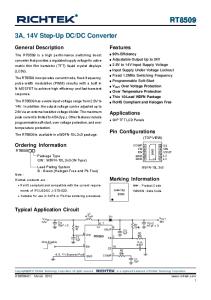
Typical Operating Circuit INPUT 2V TO 5.5V
___________________Pin Configuration ON
TOP VIEW
OFF
LIN/SKIP
1
8
SHDN
IN CAP+
CAP+
2
7
GND
CAP-
3
6
FB
SHDN 4
5
OUT
MAX1673
IN
FB
MAX1673
REGULATED NEGATIVE OUTPUT (UP TO -1 x VIN, UP TO 125mA)
OUT
CAPLIN/SKIP
GND
SO
On-Demand™ is a trademark of Maxim Integrated Products. ________________________________________________________________ Maxim Integrated Products
1
For free samples & the latest literature: http://www.maxim-ic.com, or phone 1-800-998-8800. For small orders, phone 408-737-7600 ext. 3468.
MAX1673
________________General Description
MAX1673
Regulated, 125mA-Output, Charge-Pump DC-DC Inverter ABSOLUTE MAXIMUM RATINGS IN ..............................................................................-0.3V to +6V CAP+, FB, LIN/SKIP.....................................-0.3V to (VIN + 0.3V) SHDN........................................................................-0.3V to +6V OUT, CAP-................................................................-6V to +0.3V Continuous Output Current ...............................................135mA Output Short-Circuit Duration to GND (Note 1) ....................1sec
Continuous Power Dissipation (TA = +70°C) (derate 5.88mW/°C above +70°C) ...............................450mW Operating Temperature Range ...........................-40°C to +85°C Junction Temperature ......................................................+150°C Storage Temperature Range .............................-65°C to +160°C Lead Temperature (soldering, 10sec) .............................+300°C
Note 1: Shorting OUT to IN may damage the device and should be avoided. Stresses beyond those listed under “Absolute Maximum Ratings” may cause permanent damage to the device. These are stress ratings only, and functional operation of the device at these or any other conditions beyond those indicated in the operational sections of the specifications is not implied. Exposure to absolute maximum rating conditions for extended periods may affect device reliability.
ELECTRICAL CHARACTERISTICS (VIN = V SHDN = +5V, CIN = 10µF, COUT = 22µF, CFLY = 2.2µF, TA = -40°C to +85°C, unless otherwise noted. Typical values are at TA = +25°C.) (Note 2) PARAMETER Input Voltage Range
SYMBOL VIN
Minimum Output Voltage
VOUT
Maximum Output Current
IOUT(MAX)
Output Voltage
VOUT
CONDITIONS
MIN
LIN/SKIP = GND (Skip mode)
2.0
5.5
LIN/SKIP = IN (LIN mode)
2.7
5.5
Shutdown Current (IIN Current)
Line Regulation
Load Regulation
Open-Loop Output Resistance (Dropout) Output Resistance to Ground in Shutdown Mode
2
IQ
125 LIN/SKIP = IN R1 =100kΩ, ±1%, (LIN mode) R2 = 60.4kΩ, ±1%, IOUT = 0mA to 125mA, Figure 1 LIN/SKIP = GND (Skip mode)
V
mA -3.02
-3.15 V
-2.92
-3.02
-3.12
8
16
0.035
0.2
0.1
1
mA VFB = -25mV, VOUT = -3V, LIN/SKIP = GND (Skip mode) SHDN = GND
∆VLNR
VIN = 4.5V to 5.5V, Figure 4, VREF ≠ VIN
RO
-2.90
UNITS
V
-1.5
LIN/SKIP = IN
ISHDN
∆VLDR
MAX
0
LIN/SKIP = GND
VFB = -100mV, VOUT = -3V, LIN/SKIP = IN (LIN mode) Quiescent Current (IIN Current)
TYP
IOUT = 25mA to 125mA, Figure 1
LIN/SKIP = IN (LIN mode)
0.01 %/V
LIN/SKIP = GND (Skip mode)
1
LIN/SKIP = IN (LIN mode)
0.01
LIN/SKIP = GND (Skip mode)
0.005
%/mA
LIN/SKIP = GND (Skip mode) SHDN = GND
µA
3.5
10
Ω
1
5
Ω
_______________________________________________________________________________________
Regulated, 125mA-Output, Charge-Pump DC-DC Inverter (VIN = V SHDN = +5V, CIN = 10µF, COUT = 22µF, CFLY = 2.2µF, TA = -40°C to +85°C, unless otherwise noted. Typical values are at TA = +25°C.) (Note 2) PARAMETER Switching Frequency (LIN Mode) FB Threshold
FB Input Bias Current
SYMBOL
MIN
TYP
MAX
ƒOSC
TA = +25°C
250
350
460
TA = -40°C to +85°C
205
VFBT
LIN/SKIP = GND (Skip mode)
-25
IFB
CONDITIONS
LIN/SKIP = IN (LIN mode) LIN/SKIP = GND (Skip mode)
515 0
25
150
600
1
100
VFB = -25mV
1 VIH
2V ≤ VIN ≤ 5.5V
Logic Low Input (SHDN, LIN/SKIP)
VIL
2V ≤ VIN ≤ 5.5V
kHz mV
nA
VFB = -25mV
Input Bias Current (SHDN, LIN/SKIP) Logic High Input (SHDN, LIN/SKIP)
UNITS
0.7 x VIN
µA V
0.3 x VIN
V
Note 2: Specifications to -40°C are guaranteed by design, not production tested.
_______________________________________________________________________________________
3
MAX1673
ELECTRICAL CHARACTERISTICS (continued)
Typical Operating Characteristics (Circuit of Figure 1, VIN = +5V, CFLY = 2.2µF, COUT = 22µF, TA = +25°C, unless otherwise noted.)
COUT = 47µF
40
MAX1673 TOC02
-3.05 150 COUT = 22µF
50
75
100
125
0
50
75
100
125
LOAD CURRENT (mA)
EFFICIENCY vs. LOAD CURRENT (SKIP MODE)
EFFICIENCY vs. LOAD CURRENT (LIN MODE)
VIN = 4V
70
VIN = 5V
60
80
50 40
-2.98 150
30
0
VREF ≠ VIN CIRCUIT OF FIGURE 4 20
40
60 50
VIN = 5V
40 30
70
80
100
120
60 LIN MODE 50
VREF ≠ VIN 100mA LOAD VOUT = -3V CIRCUIT OF FIGURE 4
30 0
140
20
40
60
80
100
120
140
3.5
4.0
4.5
5.0
5.5
6.0
LOAD CURRENT (mA)
LOAD CURRENT (mA)
VIN (V)
DROPOUT OUTPUT RESISTANCE vs. INPUT VOLTAGE
QUIESCENT CURRENT vs. INPUT VOLTAGE (LIN MODE)
QUIESCENT CURRENT vs. INPUT VOLTAGE (SKIP MODE)
MAX1673 TOC07
12 10 8
TA = +25°C TA = +85°C
6 4 2
12 DOES NOT INCLUDE BIAS CURRENT FOR RESISTOR DIVIDER
10 8 6 4
0
VREF ≠ VIN CIRCUIT OF FIGURE 4
0 3
4 VIN (V)
5
6
45 DOES NOT INCLUDE BIAS CURRENT FOR RESISTOR DIVIDER
40 35 30 25 20 15 10
2
TA = -40°C
2
150
SKIP MODE
40
VREF ≠ VIN CIRCUIT OF FIGURE 4
0
60
125
MAX1673 TOC09
0
100
80
QUIESCENT CURRENT (µA)
0
75
EFFICIENCY vs. INPUT VOLTAGE
VIN = 4.5V
10
QUIESCENT CURRENT (mA)
10
50
90
20
20
25
LOAD CURRENT (mA)
VIN = 4V
70 EFFICIENCY (%)
VIN = 3.5V
80
-2.99
90
MAX1673 TOC04
90
4
25
LOAD CURRENT (mA)
100
EFFICIENCY (%)
150
LIN MODE
-3.00 C CFLY = OUT 10
0 25
-3.03
-3.01 COUT = 47µF
20
0
-3.04
-3.02
100
50
0
SKIP MODE
-3.06
MAX1673 TOC06
60
200
-3.07
VOUT (V)
COUT = 22µF 80
COUT = 10µF
EFFICIENCY (%)
100
-3.08
MAX1673 TOC05
COUT = 10µF
MAX1673 TOC08
PEAK-TO-PEAK RIPPLE (mV)
120
OUTPUT VOLTAGE vs. LOAD CURRENT
250
PEAK-TO-PEAK RIPPLE (mV)
C CFLY = OUT 10
MAX1673 RTOC01
140
OUTPUT RIPPLE vs. LOAD CURRENT (SKIP MODE)
MAX1673 TOC03
OUTPUT RIPPLE vs. LOAD CURRENT (LIN MODE)
RDROPOUT (Ω)
MAX1673
Regulated, 125mA-Output, Charge-Pump DC-DC Inverter
5 0
2
3
4 VIN (V)
5
6
2
3
4 VIN (V)
_______________________________________________________________________________________
5
6
Regulated, 125mA-Output, Charge-Pump DC-DC Inverter
LOAD-TRANSIENT RESPONSE (SKIP MODE)
LOAD-TRANSIENT RESPONSE (LIN MODE)
MAX1673 TOC11
MAX1673 TOC10
125mA
IOUT 100mA/div
125mA
IOUT 100mA/div
25mA
25mA CIRCUIT OF FIGURE 4
VOUT 50mV/div
VOUT 50mV/div CIRCUIT OF FIGURE 4 250µs/div
250µs/div
LINE-TRANSIENT RESPONSE (SKIP MODE)
LINE-TRANSIENT RESPONSE (LIN MODE)
MAX1673 TOC13
MAX1673 TOC12
VIN 2V/div
5.5V
VIN 2V/div
IOUT = 100mA CIRCUIT OF FIGURE 4
VOUT 50mV/div
5.5V 4.5V
4.5V
VOUT 50mV/div IOUT = 100mA CIRCUIT OF FIGURE 4 50µs/div
50µs/div
_______________________________________________________________________________________
5
MAX1673
Typical Operating Characteristics (continued) (Circuit of Figure 1, VIN = +5V, CFLY = 2.2µF, COUT = 22µF, TA = +25°C, unless otherwise noted.)
MAX1673
Regulated, 125mA-Output, Charge-Pump DC-DC Inverter ______________________________________________________________Pin Description PIN
NAME
FUNCTION
1
LIN/SKIP
Regulation-Mode Select Input. Driving LIN/SKIP high or connecting it to IN selects LIN mode, with regulation accomplished by modulating switch resistance. Driving LIN/SKIP low or connecting it to GND selects Skip mode, where the device regulates by skipping charge-pump pulses.
2
CAP+
Positive Terminal of Flying Capacitor
3
CAP-
Negative Terminal of Flying Capacitor
4
SHDN
Shutdown Control Input. Drive SHDN low to shut down the MAX1673. Connect SHDN to IN for normal operation. OUT connects to GND through a 1Ω (typical) resistor in shutdown mode.
5
OUT
6
FB
7
GND
8
IN
Inverting Charge-Pump Output Feedback Input. Connect FB to a resistor-divider from IN (or other reference source) to OUT for regulated output voltages (Figures 1 and 4). Ground Power-Supply Positive Voltage Input
Detailed Description The MAX1673 new-generation, high-output-current, regulated charge-pump DC-DC inverter provides up to 125mA. Designed specifically for compact applications, a complete regulating circuit requires only three small capacitors and two resistors. The MAX1673 employs On-Demand™ regulation circuitry, providing output regulation modes optimized for either lowest output noise or lowest supply current. In addition, the MAX1673 includes shutdown control.
In Linear (LIN) mode or when heavily loaded in Skip mode, the charge pump runs continuously at 350kHz. During one-half of the oscillator period, switches S1 and S2 close (Figure 2), charging the transfer capacitor (CFLY) to the input voltage (CAP- = GND, and CAP+ = IN). During the other half cycle, switches S3 and S4 close (Figure 3), transferring the charge on CFLY to the output capacitor (CAP+ = GND, CAP- = OUT).
S1
CAP+
S3
IN S2
CFLY
S4
COUT OUT
CAP350kHz INPUT 5.0V
CIN 10µF
ON OFF
4 2
CFLY 2.2µF
R1 100k
8 SHDN
IN
FB
LIN SKIP
1
5 COUT 22µF
CAPLIN/SKIP
6 R1 60.4k
CAP+ MAX1673 OUT
3
Figure 2. Charging CFLY
S1
CAP+
S3
IN OUTPUT -3V
S2
CFLY
S4
COUT OUT
CAP-
GND 7
350kHz
Figure 1. Standard Application Circuit 6
Figure 3. Transferring Charge on CFLY to COUT
_______________________________________________________________________________________
Regulated, 125mA-Output, Charge-Pump DC-DC Inverter
Skip Mode In Skip mode (LIN/SKIP = GND), the device switches only as needed to maintain regulation on FB. Switching cycles are skipped until the voltage on FB rises above GND. Skip mode has higher output noise than LIN mode, but minimizes operating current.
INPUT 5.0V
MAX1673
Linear Mode (Constant-Frequency Mode) In LIN mode (LIN/SKIP = IN), the charge pump runs continuously at 350kHz. The MAX1673 controls the charge on CFLY by varying the gate drive on S1 (Figure 2). When the output voltage falls, CFLY charges faster due to increased gate drive. Since the device switches continuously, the regulation scheme minimizes output ripple, the output noise contains well-defined frequency components, and the circuit requires much smaller external capacitors than in Skip mode for a given output ripple.* However, LIN mode is less efficient than Skip mode due to higher operating current (8mA typical).
VREF 5V CIN 10µF
ON OFF
4 2
CFLY 2.2µF
3
LIN SKIP
R1 100k
8
1
SHDN
IN
FB
VOUT = -VREF x R2 R1
R2 60.4k
CAP+ MAX1673 OUT CAPLIN/SKIP
6
GND
5 COUT 22µF
OUTPUT -3V
7
Figure 4. Separate VREF for Voltage Divider
Shutdown Mode
Capacitor Selection
When SHDN (a CMOS-compatible input) is driven low, the MAX1673 enters low-power shutdown mode. Charge-pump switching action halts and an internal 1Ω switch pulls VOUT to ground. Connect SHDN to IN or drive high for normal operation.
A CFLY value of 1µF or more is sufficient to supply the specified load current. However, for minimum ripple in Skip mode, this value may need to be increased. Maxim recommends 2.2µF. Surface-mount ceramic capacitors are preferred for CFLY, due to their small size, low cost, and low equivalent series resistance (ESR). To ensure proper operation over the entire temperature range, choose ceramic capacitors with X7R (or equivalent) low-temperaturecoefficient (tempco) dielectrics. See Table 1 for a list of suggested capacitor suppliers. The output capacitor stores the charge transferred from the flying capacitor and services the load between oscillator cycles. A good general rule is to make the output capacitance at least ten times greater than that of the flying capacitor. When in Skip mode, output ripple depends mostly on two parameters: charge transfer between the capacitance values of CFLY and COUT, and the ESR of COUT. The ESR ripple contribution occurs as COUT charges. The charging current creates a negative voltage pulse across the capacitor’s ESR that recedes as C OUT charges. At equilibrium, when the voltage on C FLY approaches that on COUT, no charging current flows. Secondly, the ripple contribution due to charge transfer between capacitors creates a pulse as charge flows to COUT. Adding the two terms does not determine peakto-peak ripple because their peaks do not occur at the same time. It is best to use only the dominant term. The expression for the ripple component predominantly due to COUT ESR is:
*See Output Ripple vs. Load Current in Typical Operating Characteristics.
Applications Information Resistor Selection (Output Voltage Selection) The accuracy of VOUT depends on the accuracy of the voltage biasing the voltage-divider network (R1, R2). Use a separate reference voltage if VIN is an unregulated voltage or if greater accuracy is desired (Figure 4). Adjust the output voltage from -1.5V to -V IN in LIN mode or 0V to -VIN in Skip mode with external resistors R1 and R2 as shown in Figures 1 and 4. In either regulating mode (LIN or Skip), FB servos to 0V. Use the following equations to select R1 and R2 for the desired output voltage: R2 VOUT = - VREF R1 where VREF can be either VIN or some other positive reference source. Typically, choose a voltage-divider current of 50µA to minimize the effect of FB input current: R1 = VREF / 50µA R2 = -VOUT / 50µA
_______________________________________________________________________________________
7
MAX1673
Regulated, 125mA-Output, Charge-Pump DC-DC Inverter V – V ESR VRIPPLE(ESR) = 8 IN OUT 2 COUT f R OUT CFLY OSC
where COUT is the output capacitor value, and fMIN is the minimum oscillator frequency (250kHz). See Table 1 for a list of suggested capacitor suppliers.
Layout Considerations The MAX1673’s high oscillator frequency requires good layout technique, which ensures stability and helps maintain the output voltage under heavy loads. Take the following steps to ensure good layout:
The expression for the ripple component predominantly due to charge transfer is:
V – V 1 VRIPPLE(ESR) = 2 IN OUT fOSC ROUT (CFLY + C OUT )
• Mount all components as close together as possible. • Place the feedback resistors R1 and R2 close to the FB pin, and minimize the PC trace length at the FB circuit node. • Keep traces short to minimize parasitic inductance and capacitance. • Use a ground plane.
where CFLY and COUT are their respective capacitance values, ESRCOUT is the equivalent series resistance of COUT, ROUT is the MAX1673 open-loop output impedance (typically 3.5Ω, and fOSC is the MAX1673 switching frequency (typically 350kHz). If ESRCOUT is very small, as is likely when ceramic capacitors are used, V RIPPLE (TRANSFER) dominates. If ESR is relatively large, as with low-cost tantalum capacitors, then VRIPPLE (ESR) dominates. When operating in LIN mode, use the following equation to approximate peak-to-peak output voltage ripple: VRIPPLE =
I
OUT
2f
OSC
C
OUT
___________________Chip Information TRANSISTOR COUNT: 386 SUBSTRATE CONNECTED TO: IN
+ 2IOUT ESRCOUT
where COUT is the output capacitor value, ESRCOUT is the output capacitor’s ESR, and fOSC is the MAX1673 oscillator frequency (typically 350kHz). To ensure LIN mode stability over the entire temperature range, choose a low-ESR (no more than 100mΩ) output capacitance using the following equation:
R1
COUT = 75 x 10 - 6 R1 + R2
IOUT
Table 1. Partial Listing of Capacitor Vendors PRODUCTION METHOD
MANUFACTURER
Surface-Mount Tantalum
Surface-Mount Ceramic
SERIES
PHONE
FAX
AVX
TPS
(803) 946-0690
(803) 448-2170
Matsuo
267
(714) 969-2491
(714) 960-6492
Sprague
593D, 595D
(603) 224-1961
(603) 224-1430
AVX
X7R
(803) 946-0590
(803) 626-3123
Matsuo
X7R
(714) 969-2491
(714) 960-6492
Maxim cannot assume responsibility for use of any circuitry other than circuitry entirely embodied in a Maxim product. No circuit patent licenses are implied. Maxim reserves the right to change the circuitry and specifications without notice at any time.
8 _____________________Maxim Integrated Products, 120 San Gabriel Drive, Sunnyvale, CA 94086 408-737-7600 © 1998 Maxim Integrated Products
Printed USA
is a registered trademark of Maxim Integrated Products.