Vol. 39 (2008)
ACTA PHYSICA POLONICA B
No 2
PENNING TRAP PROGRESS IN MUNICH∗ J. Szerypo, V.S. Kolhinen, M. Bussmann, D. Habs J.B. Neumayr, C. Schürmann, M. Sewtz, P.G. Thirolf Department für Physik, Ludwig-Maximilians-Universität München 85748 Garching, Germany and Maier–Leibnitz Laboratorium, 85748 Garching, Germany
U. Schramm Forschungszentrum Rossendorf, 01314 Dresden, Germany (Received December 20, 2007) The MLLTRAP, presently under construction at the Maier—Leibnitz Laboratory (Garching), is a Penning trap system designed to decelerate, purify, charge-breed and cool the radioactive ions with the aim to perform the high-accuracy nuclear mass measurements. It involves novel techniques, like sympathetic cooling of highly-charged ions of interest with laser-cooled Mg+ ions. The goal is to reach an accuracy of 10−10 , which is required for high precision fundamental physics studies like the determination of fundamental constants and measurement of electron binding energies for QED at strong fields. PACS numbers: 39.10.+j, 07.75+h, 29.30.–h, 32.80.Pj
1. Introduction MLLTRAP [1] is a new ion trap facility that is presently under construction at the Maier–Leibnitz Laboratory, Garching. The setup is designed to combine several novel techniques to decelerate, purify, charge breed and cool fusion reaction products and perform high-accuracy nuclear mass measurements. The aim is to reach mass accuracy of about δm/m ≈ 10−10 needed for e.g. an improvement of the accuracy of fundamental constants (molar Planck constant NA h) or a unitarity test of the CKM-matrix. This accuracy can be reached in Penning trap mass measurements with highly charged ions (HCI) only. ∗
Presented at the XXX Mazurian Lakes Conference on Physics, Piaski, Poland, September 2–9, 2007.
(471)
472
J. Szerypo et al.
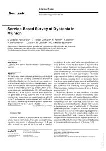
2. Project description The MLLTRAP is situated behind the 14 MeV MLL-Tandem accelerator. Fig. 1 shows the layout of the planned trap facility.
Fig. 1. Layout of the MLLTRAP facility. The set-up consist of the production (target) (1), magnetic separation of the reaction products (2), a buffer-gas stopping cell with an extraction-RFQ (MLL-IonCatcher) for the thermalisation of the ions (3), an RF mass filter for the A-selection (4) followed by a multi-reflection TOF spectrometer for the Z-selection (5), a q/A-selective four-way switchyard (multipassage spectrometer) (6), a charge breeder for highly-charged ions (7), a 24 Mg+ ion source (8), a linear Paul trap (9) for sympathetic cooling and two precision Penning traps (10) in one B = 7 T superconducting magnet.
Following the production target and the 90◦ separator dipole magnet, the first part of MLLTRAP is the ion catcher gas cell combined with an RFQ extraction system [2]. This is used to thermalize the reaction products from energies 50–500 keV/u down to a few electronvolts. Behind the ion catcher system an A-selective quadrupole mass spectrometer (QMS) and multi-reflection TOF mass spectrometer (MR-TOF-MS), based on the design by the Gießen group [3], will be installed to perform an isobaric beam purification (see [4–6]). The latter cannot be done in a Penning trap with buffer gas, since it would result in a charge-exchange and loss of HCI. A subsequent multi-passage spectrometer will be used to add a charge breeder (EBIS or laser ionization) and a Mg+ ion source to the system. The charge breeder will generate the HCIs allowing for an improved accuracy in the mass measurements. Cooling of HCI before injection into the Penning traps will be done by means of a sympathetic cooling in a linear Paul trap (also serving as a buncher). As a cooling medium for HCIs a laser-cooled 24 Mg+ ion cloud will be applied [7]. The last part in the MLLTRAP facility is a double Penning trap set-up measuring masses by applying a Time-of-Flight technique [8]. Using both Penning traps for mass measurements will allow for a reduction of systematic uncertainties.
Penning Trap Progress in Munich
473
3. Technical design 3.1. Buffer gas cell A buffer-gas stopping cell is used to thermalize and cool the beams of fusion evaporation reaction products (E ≤ 500 keV/u) in pure helium with subsequent extraction of singly- or doubly-charged ions. The setup consists of the stopping cell and an RFQ-based extraction system. After passing a thin metallic entrance window (≈ 3.5 µm Ti), the ions are stopped in helium buffer gas and are then transported via electric DC and RF fields to an extraction nozzle, where they are extracted in a supersonic gas jet into an RFQ phase space cooler ion guide. The stopping chamber of the gas cell is built in a tube with 200 mm diameter and a total length of 500 mm. DC and RF fields are used to move the stopped ions within 5–10 ms into the extraction area, where they are dragged by the gas flow through the nozzle into the extraction RFQ with a length of 340 mm. Typical He pressures in the MLL IonCatcher are 40–140 mbar and the DC gradient of 2–4 V/cm. An RF voltage of 180–200 Vpp at 800 kHz is applied to the funnel. The RFQ is operated with a DC gradient of 0.2 V/cm and an RF-amplitude between 60–120 Vpp at 800–1100 kHz. A combined stopping and extraction efficiency up to 16 % has been reached with 152 Er ions. 3.2. Penning trap The Penning trap system consists of two cylindrical traps (Fig. 2) and is placed in a single 7.0 T superconducting magnet with two homogeneous field regions (1 cm3 each). The first trap is equipped with a gas feeding line allowing for an isobaric purification in a buffer gas. This scheme will be used to test the trap system with singly-charged ions in the starting phase.
Fig. 2. A photograph of the Penning trap electrodes. The system consists of two cylindrical traps with an inner diameter of 32 mm.
474
J. Szerypo et al.
The actively screened magnet from Magnex Ltd (UK) has a 160 mm diameter warm bore. The two homogeneous field regions are located in a distance of 10 cm to the magnet center on both sides of it. In these regions the homogeneity amounts to about 0.3 ppm. The trap electrodes are made of gold-plated oxygen-free copper and aluminum-oxide insulators which are held together by aluminum bars. Both cylindrical traps have an identical electrode structure with an inner diameter of 32 mm. The lengths of the ring electrode, the first and second correction electrode are 18.5, 12.8 and 6.7 mm, respectively (as is the case of JYFLTRAP and SHIPTRAP, too). 3.3. Sympathetic laser cooling The achievable mass accuracy in TOF measurements performed in Penning traps depends inversely on the charge state of the used ions, δm/m ∝ 1/QHCI . For singly-charged ions, precision of a Penning trap mass measurement is presently on the level of 10−7 –10−8 . Thus the use of highly charged ions provides a way to improve the measurement precision to a level of δm/m ≈ 10−9 –10−10 , as needed for high accuracy fundamental physics studies. Before injecting the HCIs into the Penning traps, the momentum and energy spread must be reduced to enable an efficient injection of the ions into the magnetic field and to localize the ions at the trap center. This requires a cooling scheme that does not cause charge exchange reactions like buffer-gas cooling, while at the same time being efficient, fast and allowing cooling to temperatures down to the mK level. Recent realistic simulations show that by using a laser-cooled one-component plasma (OCP) of N = 105 ×24 Mg+ ions as a sympathetic cooling medium all these requirements can be fulfilled [7]. Simulations show that the plasma stays stable during the cooling process, since a large amount of kinetic energy of the HCI is deposited over the whole plasma bulk, see Fig. 3 middle part, and only few 24 Mg+ ions are lost due to hard binary collisions with HCI, acquiring enough energy to escape from the plasma as indicated in the lower part of Fig. 3. It also turns out that two counter-propagating laser beams are sufficient to cool the plasma and no laser frequency scanning is needed. Moreover, the re-cooling time for the 24 Mg+ ions is comparable to the stopping times in these simulations. In addition the charge-exchange times between 24 Mg+ and HCI can be estimated to be orders of magnitude longer than the cooling times [9]. Thus the molecular dynamics simulations show that it is possible to use a laser-cooled plasma to sympathetically cool HCIs for the high precision mass measurements planned for MLLTRAP.
Penning Trap Progress in Munich
475
Fig. 3. Three different views of the HCI’s (Ekin = 400 meV, QHCI = 20) passage through a 24 Mg+ plasma of density nMg = 4.23 × 10¹³ m−3 , stopped in 16.5 µs after entering into the plasma. Upper part: Real space image of a vertical slice through the center of the plasma ellipsoid showing the trajectory of the ion. Middle: Energy deposited into the plasma due to collective effects. Below: Hard binary collisions.
4. Project status A novel Penning trap facility (MLLTRAP) has been constructed and is now in its commissioning phase. While the IonCatcher gas stopping cell is fully operational, the Penning traps will be first tested with an off-line ion source during 2007 and later coupled to the gas cell for the first experiments with singly-charged radioactive ions. In parallel, a mass filter and multi-reflection Time-of-Flight spectrometer will be set up, allowing both traps to be used in high-precision measurements. Sympathetic laser cooling will be first demonstrated with experiments at the existing Paul ring trap system PALLAS [10], while a dedicated linear Paul trap will be set up in the second phase, together with the charge-breeder to provide highly-charged ions.
476
J. Szerypo et al.
Following the completion of the set-up and commissioning phase the experiments will be performed at the MLL aiming at mass measurements contributing to high-accuracy studies of fundamental constants and to unitarity tests of the CKM-matrix. As a more longterm perspective the integration of MLLTRAP into the low-energy DESIR facility at SPIRAL II (GANIL) is foreseen. This project has been partly supported by GSI under the contract number LM/HA2 and by EU(IONCATCHER) under the contract number HPRICT-2001-50022. REFERENCES [1] V. Kolhinen et al., EMIS2007 Conference Proceedings, June 24–29, 2007, Deauville, France, Nucl. Instrum. Methods, to be published. [2] J.B. Neumayr et al., Rev. Sci. Instrum. 77, 065109 (2006). [3] W.R. Plaß et al., EMIS2007 Conference Proceedings, June 24–29, 2007, Deauville, France, NIM B, to be published. [4] G. Savard et al., Phys. Lett. A158, 247 (1991). [5] V.S. Kolhinen et al., Nucl. Instrum. Methods A528, 776 (2004). [6] M. Block et al., Eur. Phys. J. A25, 49 (2005). [7] M. Bussmann, U. Schramm, D. Habs, AIP Conf. Proc. 862, 221 (2006). [8] M. König et al., Int. J. Mass Spectrom. Ion. Process. 142, 95 (1995). [9] R.E. Olson, A. Salop, Phys. Rev. A14, 579 (1976). [10] U. Schramm, D. Habs, Prog. Part. Nucl. Phys. 53, 583 (2004) and references therein.