© 2014 IJEDR | Volume 2, Issue 2 | ISSN: 2321-9939
Parametric Optimization of Face Milling Using Harmony Search Algorithm 1
Maulik B. Nagarchi, 2 Prof. D.A. Patel 1
P.G. Student, 2Associate Professor Department of Mechanical Engineering, Sardar Patel College Of Engineering, Visnagar, Gujarat technological University. 1
[email protected],
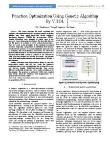
[email protected] ________________________________________________________________________________________________________ Abstract- Harmony Search (HS) Algorithm is used to determine the optimum cutting parameters for face-milling. In this work, an attempt is made to determine the optimum value of machining parameters i.e depth of cut, speed and feed rate are obtained for the improvement in the surface roughness with objective to minimize the total production cost. The research work of considering actual constraints such as allowable speed, feed rate, surface finish, tool life with the help of experiments on Vertical Machining Centre (DNM 500) for a specific( Plastic composite ) material GFRP ( Glass Fibre Reinforced Plastic ). The results obtained from Harmony Search Algorithm are validated with the help of Genetic Algorithm ( GA ). HSA has given optimum solution with higher accuracy and efficiency in comparison with GA. Key words - Milling, Optimization, Harmony search algorithm, Genetic algorithm, cost minimization. ________________________________________________________________________________________________________ I. INTRODUCTION The cost, time and quality of production are highly dependent on the cutting parameters such as the number of passes, depth of cut, speed, and feed. So, determination of optimal cutting parameters with regard to technological requirements, capability of machine tool, cutting tool and the part material is a crucial task in the process planning of parts. The quality and productivity of the parts produced by milling process is highly depends upon various process parameters used in this process. So, the selection of efficient machining parameters is of great concern in manufacturing industries, where economy of machining operation plays a key role in the competitive market. The main objective of this work is to optimize the total production cost in face-milling operation. The optimum number of passes and optimal values of the cutting parameters are found by harmony search algorithm which is a recently developed meta-heuristic algorithm. An illustrative example is used to demonstrate the capability of the HS algorithm. For validation purpose GA is used to solve the same problem and the HS results will be compared with those of GA. II. MATHEMATICAL FORMULATION Here brief overview of the face-milling is provided, and then the mathematical model of this operation is presented. Face milling The machining operation can be divided into roughing and finishing operation, as shown in Fig : 1 In rough machining, the length of the cutter travel is given by
Lr L+a p b Where L is the length of the work piece,
a p is the approach distance and b is an arbitrary distance to avoid possible accidents
and damages. Here, for simplicity the parameter b is taken to be zero. The approach distance for symmetrical milling is Given as: 2
D D w ap 2 2 2
2
where D is the diameter of the tool and w is the width of work-piece. In finish machining, the relation L f
L Db
L f is the cutter travel length for the finish pass.
IJEDR1402072
International Journal of Engineering Development and Research (www.ijedr.org)
1722
© 2014 IJEDR | Volume 2, Issue 2 | ISSN: 2321-9939
Fig-1: Schematic diagram and face-milling operation. Objective Function The cost of single pass U is given by
U k 0 t m kt z Where
tm
is the machining expressed as tm
In above equation, the length of cutter-travel,
tm k0t p k0 Lh1 h2 TR
Lt zsN is depending on whether the rough milling or finish milling is followed, z is the
Lt
number of teeth on the cutter and s is the feed. The first term in above equation of cost of single pass is referred to as the machining cost, and the second term is related to the tool cost. The third and the fourth terms represent the cost of tool exchange and the cost involved in return and tool advance/retract, respectively. Constraints The equation of the cost of single pass U is subjected to following constraints. 1.
Tool-life (T) Equation of tool life is taken from, Typical Examples and Problems in Metal Cutting and Tool Design. The tool life in face milling is expressed as:
cv kv D qv T xv yv tv pv va s w z m
where V is the cutting speed and a is the depth of cut. D, w and z are the diameter of the cutter, width of work-piece and number of teeth, respectively 2.
qv , tv
and
pv
are constant terms.
Available speed (V) Optimum cutting speed should be lay within the permissible range of the machine.
Vmin V Vmax
Where Vmin and V max= speed. 3.
DNmax /1000 are minimum and maximum cutting speed, respectively and N is the spindle
Depth of cut (a)
IJEDR1402072
International Journal of Engineering Development and Research (www.ijedr.org)
1723
© 2014 IJEDR | Volume 2, Issue 2 | ISSN: 2321-9939 Depth of cut has to be within the specified range.
amin a amax 4.
Feed rate (s) The constraint on the feed is expressed as:
smin s smax The maximum surface finish should be smaller than or equal to the required surface finish under the existing machining conditions. The surface finish (Ra) in face-milling is given by
0.0321 s , where re is the nose-radius of the cutting-edge. And taken from Fundamentals of Metal Machining Ra re 2
and Machine Tools. Combining above both equation, the following result are obtaining:
smin 5.
2 re Ra s min smax , 0.0321
Cutting force (F) Equation of cutting force is taken from, Typical Examples and Problems in Metal Cutting and Tool Design. The cutting force (F) must not be greater than a certain maximum value (F) given by the strength and stability of the machine and the cutting tool. The peripheral cutting force is given by
BtF Z Pf FZ CF a xF s yF qF wF K F spindle ( n )is ignored ( w =) C and K are constants s D nof In the above equation, the effect of rotational frequency the f F s F with regard to the tool and work-piece material. 6.
Cutting power(P) Power required for the cutting operation should not exceed the effective power transmitted to cutting point by the machine tool:
Pm
Pm
Pc n
Pc
are the nominal motor power and cutting power, respectively, and n is the overall efficiency of machine tool. In milling process, mean value of power is given as where
and
Pm Where
Fz
FzV 6120
is the mean peripheral cutting force.
III. EXPERIMENTAL WORK In this study the Process parameter of milling process vessel optimized for minimizing the production cost by applying Harmony Search Algorithm. For this study the milling process problem and data are taken from industry and it is a real problem of the industry. Material selection Work Piece of GFRP with Length of 150 mm, Width 45 and thickness of 15 mm has been selected for the experimental work. The reason behind the selection is, GFRP are increasingly being used for different engineering applications because of their superior qualitative advantages include high ratio of strength to weight , high fracture strength and toughness , excellent thermal and corrosion resistance. For machining of GFRP and advanced materials requiring high precision, complex shapes and high surface finish, selection of tool to be widely processed and applicable in manufacturing industries. Among the various metallic and non metallic Tool, S.S, Carbide steel, and Tungsten carbide have been selected as a tool with diameter of 50 mm With No of 4 Tooth. Specification Of vertical machine center DNM 500 vmc machine used to take experiments, machine specification are as follows:
IJEDR1402072
International Journal of Engineering Development and Research (www.ijedr.org)
1724
© 2014 IJEDR | Volume 2, Issue 2 | ISSN: 2321-9939
Maker. Model. Table size. X,Y,Z Travel. Maximum Tool Diameter. Tool Shank. Maximum work-piece weight. Maximum spindle speed. Maximum cutting feed(X,Y,Z). Maximum rapid feed rate(X,Y,Z) No of tools Spindle power. Machine weight. Machine size.
Table-1: Machine specification. Doosan infracore DNM 500 1200 X 540 (mm) 1020,540,510 (mm) 160 (mm) BT40 500 (kg) 8000 (rpm) 10,10,10 (m/min) 30,30,30(m/min) 30 12 (kw) 7000 (kg) 4 X 2.5 (m)
Mathematical Description Table-2: Nomenclature and Numerical data for the face milling operation [A] Milling cost and constraints Overhead cost 5 k (Rs/min) o
Cost of cutting edge
kt (Rs/cut.edge)
160
Tool-exchange time
te (min/cut edge) t p (min/piece)
3
Tool Return time
h1 (min/mm)
5 x 10⁻⁴
Tool advance return time
h2 (min)
3
amin (mm)
1
amax (mm)
4
smin (mm/tooth)
0.1
smax (mm/tooth)
0.6
Vmin (m/min)
50
Vmax (m/min)
300
TR (min)
180
Ra (rough) (µm)
10
Ra
3
Preparation time
Depth of cut
Feed ( x1 )
Cutting speed ( x2 ) Tool replacement life Surface roughness( x5 )
(finish)(µm)
2
Force ( x3 )
Fmax
(KN)
10
Power ( x4 )
Pmax
(KW)
12
[B]. constant and exponents in face milling Equation constant/exponents Tool-life C 445, m 0.32, x v
Force
v
0.15, yv 0.35, pv 0, qv 0.2, tv 0.2, Kv 1.0
CF 534.6, xF 0.15, yF 0.74, tF 1, wF 0, qF 1.0, pF 1.0, kF 1.0
IV. OPTIMIZATION METHODOLOGY The optimization problem has four variables including number of passes and the corresponding speeds, feed and depth of cut for each pass. here result obtained for single rough pass from depth of cut 1 mm to 4 mm and for single finish pass from depth of cut 1 mm to 2 mm using harmony search algorithm as well as Genetic algorithm. The program for harmony search algorithm is developed in Matlab 7.8.0.347 and genetic algorithm is applied in the same software using inbuilt GA Tool.
IJEDR1402072
International Journal of Engineering Development and Research (www.ijedr.org)
1725
© 2014 IJEDR | Volume 2, Issue 2 | ISSN: 2321-9939
Harmony search The harmony search algorithm which is a meta heuristic optimization algorithm has been recently developed By Z W Geem. The HS algorithm is simple in concept, few in parameters, and easy in implementation. It has been successfully applied to various benchmark and real world problems. Steps of harmony search algorithm are shown as flowchart in Fig. 2 .
Fig-2: HSA Flow chart Steps of HSA are as follows. Step 1. Initialize the problem and algorithm parameters. Step 2. Initialize the Harmony Memory (HM). Step 3. Improvise a New Harmony memory. Step 4. Update the Harmony memory. Step 5. Check the stopping criterion. V. RESULT AND DISCUSSION A. The results are obtained using the harmony search algorithm method.
IJEDR1402072
International Journal of Engineering Development and Research (www.ijedr.org)
1726
© 2014 IJEDR | Volume 2, Issue 2 | ISSN: 2321-9939 Table-3: Optimized cutting parameters and cost in face milling. [A]. For a single rough pass Feed rate Depth of cut (a) (mm)
x1 s
1 2 3 4
(mm/tooth) 0.599 0.586 0.599 0.591
Speed
Force(F)
Power(P)
x2 V x3 F x4 F m/min 160.552 156.1975 146.8595 131.1641
KN 5.879 6.256 6.256 6.256
KW 8.125 10.638 11.244 9.171
Force(F)
Power(P)
Surface roughness (µm)
Cost (₨)
4.034 5.582 8.916 6.701
12.6018 12.6183 12.6696 12.7768
[B]. For a single finish pass Feed rate
Depth of cut(a) (mm)
x1 s
x2 V x3 F x4 F
(mm/tooth 0.293 0.294
1 2
Speed
m/min 178.788 178.767
KN 6.674 6.162
KW 8.087 8.127
Surface roughness (µm)
Cost (₨)
3 3
13.3879 13.3996
Result analysis
Fig- 3: Depth of cut and feed rate graph
Fig-4: Depth of cut and speed grap
Fig-5: Depth of cut and cost graph B. The results are obtained using the Genetic algorithm method. Table-4: Optimized cutting parameters and cost in face milling. [A]. For single rough pass Depth of cut (a) (mm) 1 2
IJEDR1402072
Feed rate
Speed
Force(F)
Power(P)
x1 s
x2 V
x3 F
x4 F
(mm/tooth) 0.434 0.479
(m/min) 198.633 173.059
(KN) 0.865 1.735
(KW) 11.978 11.926
Surface roughness (µm)
Cost (₨)
6.059 7.352
12.6861 12.7201
International Journal of Engineering Development and Research (www.ijedr.org)
1727
© 2014 IJEDR | Volume 2, Issue 2 | ISSN: 2321-9939 3 4
0.392 0.380
174.689 169.130
2.154 2.728
11.966 11.421
4.923 4.628
12.8982 12.9650
[B]. For single finish pass Feed rate
Depth of cut (a) (mm)
Speed
Power(P)
x2 V x3 F x4 F
x1 s
(mm/tooth) 0.206 0.234
1 2
Force(F)
m/min 257.946 222.252
KN 0.498 1.022
KW 11.669 11.779
Surface roughness (µm)
Cost (₨)
3 3
13.3849 13.4162
Result analysis
Fig-6: Depth of cut and feed rate graph
Fig-7: Depth of cut and speed graph
Fig-: Depth of cut and cost graph Table-5: Comparison of HSA and GA for single rough and finish pass. [A]. For single rough pass. HSA Depth of cut(a) (mm) 1 2 3 4
GA Cost(Rs) 12.6018 12.6183 12.6696 12.7768
Depth of cut(a) (mm) 1 2 3 4
Cost(Rs) 13.3879 13.3996
Depth of cut(a) (mm) 1 2
Cost(Rs) 12.6871 12.7201 12.8982 12.9650
[B]. For single finish pass. HSA Depth of cut(a) (mm) 1 2
IJEDR1402072
GA Cost(Rs) 13.3849 13.4162
International Journal of Engineering Development and Research (www.ijedr.org)
1728
© 2014 IJEDR | Volume 2, Issue 2 | ISSN: 2321-9939 VI. CONCLUSIONS In the current work, optimization of milling process is carried out for the face milling of GFRP material . An objective function is developed by substituting the constraints (obtained by considering the actual machining parameters )for minimizing the manufacturing cost.. The results shows the following points. Both HSA and GA has given optimum solution for each single rough pass and finished pass for surface finish as major constraint. Analysis has demonstrated that the HSA takes very less time compared to GA. The table resembles that the total cost obtained from HSA is better than GA and HSA has given optimum solution with higher accuracy and efficiency in comparison with GA. REFERENCES [1]. [2].
[3]. [4].
[5]. [6].
[7]. [8].
[9]. [10]. [11]. [12]. [13]. [14]. [15]. [16]. [17]. [18].
Manjarres D. “A survey on applications of the harmony search algorithm”, Elsevier, Engineering Applications of artificial intelligence 26 (2013), 1818-1831. Sreenivasulu Reddy “Optimization of Surface Roughness and Delamination Damage of GFRP Composite Material in End Milling using Taguchi Design Method and Artificial Neural Network”, Elsevier-International Conference on DESIGN AND MANUFACTURING, Procedia Engineering 64 ( 2013 ) 785 – 794. Yildiz Ali R. “A new hybrid differential evolution algorithm for the selection of optimal machining parameters in milling operations”, Elsevier- Applied soft computing, 13(2013) 1561-1566. Pandey Piyush, “Process Parametric Optimization of CNC Vertical Milling perform the parametric optimization of CNC end milling machine tool in varying condition.” IOSR Journal of Mechanical and Civil Engineering, Volume 6, Issue 5 (2013), PP 34-42. Sriprateep Keartisak, “A Comparative of the Optimization in Machining Conditions for Part face-milling Operations”, Australian Journal of Basic and Applied Sciences, 6(8): 93-98, (2012). Selvam Milon D., “Optimization Of Machining Parameters For Face Milling Operation In A Vertical Cnc Milling Machine Using Genetic Algorithm” Engineering Science and Technology: An International Journal, Vol.2, No. 4, August (2012). Baharudin,B.T.H.T “Experimental Investigation of HSS Face Milling to AL6061 using Taguchi Method”, ElsevierProcedia Engineering 50 ( 2012 ) 933 – 941. Lee Kang Seok, “Discrete Size And Discrete-Continuous Configuration Optimization Methods For Truss Structures Using The Harmony Search Algorithm”, International journal of optimization in civil engineering, vol-1, :107-126., (2011). Jaberipour Majid “Two improved harmony search algorithms for solving engineering optimization problems”, Elsevier- Commun Nonlinear Sci Numer Simulat 15 (2010) 3316–3331. Rao R. Venkata, “Parameter optimization of a multi-pass milling process using non-traditional optimization algorithms”, Elsevier- Applied Soft Computing 10 (2010) 445–456. Zain Azlan Mohd,” Application of GA to optimize cutting conditions for minimizing surface roughness in end milling machining process”, Elsevier-Expert Systems with Applications 37 (2010) 4650–4659 Geem Z. W., “A New Heuristic Optimization Algorithm: Harmony Search”, Simulation, 76:2, 60 68(2001), simulation councils inc. Ingram,Gordon , “Overview of Applications and Developments in the HarmonySearchAlgorithm” Springer: MusicInspired Harmony Search Algorithm: Theory and Applications (Editor Z. W. Geem), vol. 191,(2009). Yang X -She, “Harmony Search as a Meta heuristic Algorithm”, Springer : Music-Inspired Harmony Search Algorithm: Theory and Applications (Editor Z. W. Geem),, vol. 191,(2009). Zarei O. “Optimization of multi-pass face-milling via harmony search algorithm”, Elsevier- n Journal Of Materials Processing Technology 209 (2009) 2386-2392. Wang Z.G., “Optimization of multi-pass milling using parallel genetic algorithm and parallel genetic simulated annealing”, Elsevier-International Journal of Machine Tools & Manufacture 45 (2005) 1726–1734. Lee Seok “A new meta-heuristic algorithm for continuous engineering optimization: Harmony search theory and practice”, Elsevier, computer methods in applied mechanics and engineering, Vol: 194,(2005),pp 3902-3933. Shunmugam M.S. “Selection of optimal conditions in multi-pass face-milling using a genetic algorithm”, International Journal of Machine Tools & Manufacture 40 (2000) 401–414
IJEDR1402072
International Journal of Engineering Development and Research (www.ijedr.org)
1729