Area-I/O Flip-Chip Routing for Chip-Package Co-Design Jia-Wei Fang1 and Yao-Wen Chang1,2 1 Graduate
Institute of Electronics Engineering, National Taiwan University, Taipei 106, Taiwan 2 Department of Electrical Engineering, National Taiwan University, Taipei 106, Taiwan
Abstract— The area-I/O flip-chip package provides a high chip-density solution to the demand of more I/O’s in VLSI designs; it can achieve smaller package size, shorter wirelength, and better signal and power integrity. In this paper, we introduce the routing problem for chip and package co-design and present the first work in the literature to handle the multiple Re-Distribution Layer (RDL) routing problem for flip-chip designs, considering pin and layer assignment, total wirelength minimization, and chip-package co-design. Our router adopts a two-stage technique of global routing followed by RDL routing. The global routing assigns each block port to a unique bump pad via an I/O pad and decides the RDL routing among I/O pads and bump pads. Based on the minimum-cost maximumflow algorithm, we can guarantee 100% RDL routing completion after the assignment and the optimal solution with the minimum wirelength. The RDL routing efficiently distributes the routing points between two adjacent bump pads and then generates a 100% routable sequence to complete the routing. Experimental results based on 10 industry designs demonstrate that our router can achieve 100% routability and the optimal routing wirelength under reasonable CPU times, while related works cannot.
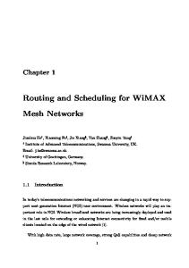
I. I NTRODUCTION The increasing complexity and decreasing feature size of VLSI designs make the demand of more I/O’s a significant problem to package technologies. The flip-chip package, as shown in Figure 1(a), is an advanced packaging technology and created for higher integration density and larger I/O counts. Bump Ball
I/O Pad (I/O Buffer)
Bump Pad
Bump
changing the placement of the I/O pads. Bump balls are placed on the RDL and use the RDL to connect to I/O pads by bump pads. For large-scale designs, multiple re-distribution layers (multi-RDL’s) might be needed to handle the increasing problem size, for which layer assignment also needs to be considered. Therefore, it is desirable to consider multi-RDL’s for the interconnections between the I/O pads and the bump pads (balls) [8]. There are two types of flip-chip structures: peripheral-I/O flip-chips (see Figure 2(a)) and area-I/O flip-chips (see Figure 2(b)). I/O pads are placed along the boundary of a die in a peripheral-I/O flip-chip, while they are placed in the whole area of a die in an area-I/O flip-chip. For the routing on a peripheral-I/O flip-chip, I/O pads are routed from the outer boundary to the inner bump pads. If an I/O pad is not assigned to any bump pad before routing, then a router has the freedom to assign an I/O pad to bump pads during routing. Fang et al. [4] first divided a peripheral-I/O flip-chip into four sectors, as illustrated in Figure 2(a). Then, for each sector, this free-assignment routing problem on a single RDL was solved by a network-flow formulation without considering U-turn routes. For the routing on an area-I/O flip-chip (see Figure 2(b)), in contrast, U-turn routes are often inevitable, and thus dividing the flip-chip into to four independent sectors may lead only to suboptimal solutions. Consequently, this routing problem is much harder than the peripheralI/O one. Further, the area-I/O flip-chip is more popular for high-speed applications because this structure can lead to smaller package size (see the size differences between Figures 2(a) and (b)), shorter wirelengths among I/O pads and bump pads, and better signal and power integrity.
(a)
I/O Pad
Bump Pad
Flip-Chip
PASV (L3)
Bump
Redistribution Layer Top Metal Other routing under bump Core Cells
Fig. 1.
Cut Line U-turn Route among Sectors (a) (b) Fig. 2. (a) RDL Routing for a Peripheral-I/O Flip-Chip (in Four Sectors). (b) RDL Routing for an Area-I/O Flip-Chip.
Top Metal M7 M1 I/O Buffers
(b) (a) Flip-Chip Package. (b) Cross Section of RDL.
A flip-chip is not a specific package, or even a package type, e.g., pin grid arrays (PGA’s) or ball grid arrays (BGA’s). The flip-chip describes a method of electrically connecting a die to a package carrier. The flipchip technology is the major choice for high-speed applications because of the following advantages: reduced signal inductance, reduced IR drop, reduced package footprint, etc. To further enhance these advantages, recent IC’s place I/O pads (buffers) in the whole area of a die, instead of just placing them along the die boundary. Consequently, this placement results in shorter wirelength, higher chip density, and better signal and power integrity. For the flip-chip applications, typically the top metal or an extra metal layer, called a re-distribution layer (RDL for short) as illustrated in Figure 1(b), is used to redistribute I/O pads to bump pads without —————————————————————————————— work was partially supported by Etron, SpringSoft, TSMC, and National Science Council of Taiwan under Grant No’s NSC 96-2628-E-002-248-MY3, NSC 96-2628-E-002-249-MY3, NSC 96-2221-E-002-245, NSC 96-2752-E002-008-PAE, and NSC 096-2917-I-002-120.
∗ This
978-1-4244-2820-5/08/$25.00 ©2008 IEEE
In addition to the package-level RDL routing, the chip-level routing from block ports to I/O pads is of significant importance because chippackage co-design provides greater design flexibility and becomes more popular for modern circuits. As shown in Figures 3(a) and (b), after floorplanning the circuit blocks and the I/O buffers, we need to route not only from the block ports to the I/O pads (chip-level routing), but also from the I/O pads to the bump pads (package-level routing). Here, the blocks and the I/O buffers cannot overlap with each other, but they can overlap with the bump pads since they are on different layers. In a traditional package-design flow, the design information from chips (e.g., the wiring between a block port and an I/O pad) is not considered. As a result, package-level routing without considering the chip-level information may incur unsolvable restrictions/violations for the chiplevel design, and vice versa. In order to improve design convergence, the area-I/O flip-chip routing shall optimize the RDL routability by chip-package co-design which simultaneously considers the assignment between block ports and I/O buffers and performs assignment and routing of the I/O buffers and bump pads. A. Previous Work As mentioned earlier, there is no existing work in the literature specifically for the area-I/O multi-RDL routing problem. Two related
518
Bump Pad Block
I/O Buffer
Block Port (a)
I/O Pad (b)
Fig. 3. (a) Chip-level Routing from Block Ports to I/O Pads. (b) Package-level RDL Routing from I/O Pads to Bump Pads.
works are the pad routing for area-array ICs [7] and the routing for peripheral-I/O flip-chips [4]. The work [7] first used the weighted bipartite matching algorithm to generate a netlist between bump pads and I/O pads, and then routed the nets sequentially by A*-search maze routing. The sequential routing is greedy, and thus its solution quality (routability and wirelength) is often limited. Recently, Fang et al. in [4] addressed the single RDL routing problem for the peripheralI/O structure, assigned I/O pads to bump pads by dividing a flip-chip into four sectors, and applied a network-flow formulation to handle the problem for each sector. Since U-turn routes and interactions among the sectors are not considered in its approach, this networkflow formulation cannot handle the area-I/O routing problem. Further, it does not consider the layer assignment of wires for multi-RDL’s. Other related works are the routing for PGA/BGA packages and flip chips, including [1], [3], and [5]. The work [1] presented a PGA router while [5] provided a BGA router. These two routers are multilayer routers without considering the pin assignment problem and total wirelength minimization. The work [3] presented a single-layer flipchip router without considering the pin assignment and the area-I/O structure. In addition to the aforementioned differences, a major deficiency of these previous works is that they handle the package-level routing from I/O pads to bump pads alone, without considering the chip-level routing from block ports to I/O pads. As discussed earlier, considering package-level routing alone might incur constraint violations for chiplevel designs, causing significant problems in design convergence.
II. P ROBLEM F ORMULATION We introduce the notation used in this paper and formally define the RDL routing problem for the chip-package co-design. Figure 4(a) shows the modelling of the routing structure of the area-I/O flip-chip package. Let Q be the set of I/O pads, and B be the set of bump pads. For practical applications, each I/O pad is assigned to one bump pad. Let L = {l1 , l2 , .., lf } be a set of f bump pad columns in the center of the package, and let W = {w1 , w2 , .., wf } be a set of f bump pad rows in the center of the package. Each bump pad column/row (li /wj ) consists of a set of f bump pads, and each bump pad is represented by bi,j . An interval is formed by two adjacent bump pads, and a tile is constructed by four adjacent bump pads. Although we can have multiRDL’s for current technology, vias are still not allowed to be inserted into wires for better signal integrity. Therefore, each route among I/O pads and bump pads has to be completed on a single layer, and thus wire crossings are not allowed. Figure 4(b) shows the modelling of the chip-level netlist generation for chip-package co-design. Consider chip-level routing. Let P be the set of block ports. The number of I/O pads is larger than or equal to the number of block ports, i.e., |Q| ≥ |P |, and each block port pi can be assigned to only one I/O pad qj . Each I/O pad can be an input or output buffer depending on which block port it connects. The I/O pads are divided into several types according to their sizes. In real designs, the assignment among the block ports and these types is predefined. Further, the capacity for interconnecting bump pads, I/O pads, and block ports among different RDL’s should also be considered. Bump Pad
I/O Pad
w1
Block Port Interval
w2
Net
w3 Tile
w4
l1
l3
l2 (a)
l4
Block
I/O Buffer
(b)
Fig. 4. (a) Routing Structure in a Flip-Chip Package. (b) Chip-level I/O Netlist among Block Ports and I/O Pads.
B. Our Contributions We present the first paper to handle the area-I/O multi-RDL routing problem. It can be used to complete the RDL routing during/after chiplevel floorplanning/placement, facilitating the routability optimization in package-level routing for chip-package co-design. The key features of this work include (1) pin and layer assignment, (2) RDL routability optimization considering U-turn routes, (3) total wirelength minimization, and (4) chip-package co-design. We present a unified network-flow formulation to simultaneously consider the pin and layer assignment of block ports to bump pads via I/O pads and the routing among them. The RDL routing result and the chip-level I/O netlist (the netlist among block ports and I/O pads) can be used in the chip-level routing (i.e., the routing in other metal layers) to achieve chip-package codesign. Our algorithm guarantees to find an optimal solution with the minimum wirelength for the addressed problem. It consists of two phases. The first phase is the global routing that assigns each block port to a unique bump pad via an I/O pad and decides the routing layer between each I/O pad and each bump pad. By the minimumcost network-flow formulation, we can guarantee 100% RDL routing completion after the assignment. The second phase is the RDL routing that efficiently distributes the routing points between two adjacent bump pads and then generates a 100% routable routing sequence to complete the routing. Experimental results based on 10 real designs from the industry demonstrate that our router can achieve 100% RDL routing completion and the optimal routing wirelength under reasonable CPU times, while related works result in significantly inferior solution quality. The rest of this paper is organized as follows. Section II gives the formulation of the routing problem of the chip-package co-design. Section III details our global and RDL routing algorithms. Section IV reports the experimental results. Finally, our conclusion is given in Section V.
We formally define the addressed routing problem as follows: Problem 1: Given the number of RDL’s and a placement of blocks, I/O pads (buffers), and bump balls, the multi-RDL routing problem for chip-package co-design is to assign a set P of block ports to a set Q of I/O pads and connect the I/O pads to a set B of bump pads so that there is no wire crossing in each RDL, the design rules for chip- and package-level routing are satisfied, and the total wirelength is minimized. Note that this placement can be generated with or without considering the I/O netlist among block ports, I/O pads, and bump pads. III. T HE ROUTING A LGORITHM A. Algorithm Overview Figure 5 shows our routing flow for the chip-package co-design problem. Our algorithm consists of two phases: (1) global routing based on the minimum-cost maximum-flow (MCMF) formulation [2], and (2) RDL routing based on the passing-point assignment, the net-ordering determination, and the maze routing. In the first phase, we construct the flow network G to solve the assignment of the block ports to the bump pads via the I/O pads. Since we have multiple RDL’s for routing, the assignment should handle the layer assignment. However, vias are not allowed in RDL routing for better signal integrity. Hence, there should be no wire crossing. We prevent the wire crossings by restricting the edges in the flow network G from intersecting each other. After applying the MCMF algorithm, we obtain the flows representing the routes from block ports to bump pads via I/O pads for the nets. Those flows give the global-routing paths for the nets. In the second phase, we use the passing-point assignment, the netordering determination, and the maze routing to determine RDL routes.
519
Blocks (Block Ports) I/O Buffers (I/O Pads) Bump Pads Global Routing
pad. Figure 6(b) illustrates how to modify the flow network G for multiple RDL’s. Inserting vias is not allowed in the multi-RDL routing for better signal integrity. Each I/O pad is first assigned to one RDL and then assigned to a bump pad. On the other hand, each RDL has its own intermediate nodes and tile nodes and shares the same bump pads. Therefore, each route among I/O pads and bump pads can be completed on�a single layer. The MCMF algorithm can be solved in time O(|V |2 |E|) [2], where V is the vertex set in the flow network. We thus have the following theorem. Theorem 1: Given a flow network G = (V, E), � the r-layer RDL global-routing problem can be solved in O(|rV |2 |rE|) time. Note that the number of RDL’s for current technology is very small (say, one or two). Therefore, r can be considered a constant for practical applications.
RDL Routing
Intermediate Nodes and Tile Nodes Insertion Graph Construction Cost and Capacity Assignment Flow Network Solving
Passing Point Assignment Net Ordering Determination Maze Routing
RDL Routing Result Output
bi , j +1
Chip-level I/O Netlist Output
bi +1, j +1
Chip-level Routing
Fig. 5.
Intermediate Node
dk
The Routing Flow of Chip-Package Co-design.
tu
A passing point is the point for a net to pass through an interval. First, we find the passing points for all nets passing through the same interval. For all nets that pass through the same interval, we evenly distribute these passing points. Second, we use a net-ordering determination technique to create a routing sequence in each tile that can guarantee to route all nets. Finally, we use maze routing to route each net based on the sequence obtained from the net-ordering determination.
b1
bi +1, j
bi , j
I/O Pad
(a) Layer 2
4 2
3
B. Global Routing 1) Basic Network Formulation: We describe how to construct the flow network G to perform the concurrent assignment and routing for the chip-package co-design. As shown in Figure 6(a), we define D = {d1 , d2 , .., dh } as a set of h intermediate nodes. Each intermediate node represents an interval (bi,j , bi,j+1 ) ((bi,j , bi+1,j )) in a bump pad column (row). T = {t1 , t2 , .., tu } is a set of u tile nodes. Each tile node represents a tile (bi,j , bi,j+1 , bi+1,j+1 , bi+1,j ). We construct a graph G = (P ∪ Q ∪ D ∪ T ∪ B ∪ {s, t}, E), where E denotes the edge set, s is the source node, and t is the sink node. The node for each I/O pad has a capacity of 1 because it can be assigned to only one block port. Each intermediate node has a capacity of Cd , where Cd represents the maximum number of nets that are allowed to pass through an interval. Each tile node has a capacity of Ct , where Ct represents the maximum number of nets that are allowed to pass through a tile. We will detail the determination of the capacity later. There are ten types of edges: 1) the edge from a block port (node) to an I/O pad (node), 2) the edge from an I/O pad to an intermediate node, 3) the edge from an I/O pad to a tile node, 4) the edge from an I/O pad to a bump pad, 5) the edge from an intermediate node to a tile node, 6) the edge from an intermediate node to a bump pad, 7) the edge from a tile node to an intermediate node, 8) the edge from a tile node to a bump pad, 9) the edge from the source node to a block port, and 10) the edge from a bump pad to the sink node. Each edge is associated with a (cost, capacity) tuple to be explained in the following subsections. Recall that we do not allow crossings for all wires in each layer. Since E represents the potential global-routing paths of all nets, we can guarantee that no wire crossing will occur if there exists no crossing among edges. Thus we construct all edges and avoid crossings of them at the same time. Figure 6(c) shows an example flow network G for a single layer. The last two types of edges are not shown here. An edge is constructed between a block port and an I/O pad if the block port is assigned to the I/O pad of the same buffer type. Each I/O pad connects either to its nearest intermediate node or to its nearest tile node. An I/O pad also connects to a bump pad if the distance between them is shorter than that between an intermediate node and a bump pad. According to the flip-chip layout guide [8], we cannot insert vias in the area of a bump pad to allow an I/O pad to route from the chip-level metal layers to the RDL. If an I/O pad is placed inside the area of a bump pad (as that in the bottom-left bump pad b1 in the top side of Figure 6(c)), hence, we need not construct an edge between this I/O pad and the bump pad. Edges are constructed among this I/O pad and the adjacent intermediate nodes of the bump
Bump Pad
Tile Node
1
2
1 2
2
1 1
Layer 1
I/O I/O I/O I/O Pads Pads Pads Pads (Type 1) (Type 2) (Type 3) (Type 4) Block Port
(b) (c) Fig. 6. (a) Intermediate Nodes and Tile Nodes. (b) Flow Network for Multilayer. (c) Flow Network for Single-layer.
2) Capacity Assignment and Node Construction: We now introduce the capacity assignment for the edges, the I/O pads, the intermediate nodes, and the tile nodes. Figure 7(a) shows the capacity assignments for all ten types of edges in the flow network. The capacity of an edge e is set to 1 for the following cases: • e is from a block port to an I/O pad, • e is from an I/O pad to an intermediate node, a tile node, or a bump pad, • e is from an intermediate node or a tile node to a bump pad, • e is from the source node to the block ports, or • e is from each bump pad to the sink node. Recall that an intermediate node has the capacity of Cd , where Cd is the maximum number of nets allowed to pass through this intermediate node. This means that the capacity of the incoming edge of an intermediate node equals Cd . If e is an incoming edge of a tile node, then the capacity of e is Ct , where Ct is the maximum number of nets allowed to pass through the tile node. In each RDL, since we do not insert vias into wires, we can calculate Cd and Ct according to the design rules. In order to model this situation, as shown in Figure 7(b), we decompose each intermediate node di into two nodes d�i and d��i , and an edge is connected from d�i to d��i with capacity Cd . All incoming edges of di are now connected to d�i , and all outgoing edges of di are now connected from d��i . Each tile node tj is also decomposed into two tile nodes, and the capacity of a tile node tj is set to Ct , where Ct is the maximum number of nets allowed to pass through this tile node tj . No matter for single- or multi-RDL’s, if there are i I/O pads in a tile, Ct of the tile is set to �Ct ×(1−k)�, where k is the area portion of the i I/O pads in the tile; the reason is that each I/O pad is punched through all redistribution layers and thus the corresponding routing resource is occupied. We set the capacity of each I/O pad to 1 because each I/O pad can be assigned to only one block port. Figure 8(a) gives a worstcase scenario of congestion in a tile, in which the maximum number of nets passing through a tile is 2Cd while there is no overflow in each interval. If we do not use the tile node, the maximum number of nets in Figures 8(a) can exceed the capacity of a tile (i.e., 2Cd > Ct ). Since the capacity of each tile node is well modelled in our flow network, we can totally avoid this congestion problem.
520
node 4 to intermediate node 3 as shown in Figure 9(b).
t 1
1
1
1 Cd
di
1 Ct
1 1
Ct
1
1
2
: I/O Pads : Block Ports
Cd
1
1
1
1
: Intermediate Node : Tile Nodes
di’’
Fig. 7.
1 s
Block
Bump Pad
Net Edge Grid 1
Cd Block Port
(a) Fig. 8.
(b)
(a) Congestion in a Tile. (b) Net Configuration on a Chip.
3) The Cost of Edges: The cost function of each edge is defined by the following equation: TL , (1) 2 where WL denotes the Manhattan distance between two terminals of an edge, and TL is the length of a tile. α and β are both integer variables and are only applied to the edges among block ports and I/O pads. As shown in Figure 8(b), the length of each grid equals TL . In order to make the chip-level I/O netlist suitable for chip-level routing, we use the grids to avoid wire congestion. When an edge passes through a set of grids, the number of nets (represented by direct connections) among blocks in this set is summed up into α. The number of edges from block ports to I/O pads in the set of grids is summed up into β. For example, since there is only one net routing through the grid 1, α is increased by 1. In the grid 2, the number of associated edges is 2, and thus β is increased by 2. Since there may be many edges connecting to a block port and an edge passing through several grids, the cost function selects the edge with less wire congestion. The costs of the edges inside I/O pads, intermediate nodes, and tile nodes are all set to 0 since the lengths of these edges are all 0. The costs of the edges from the source node to the block ports and the costs of the edges from the bump pads to the sink node are also set to 0. To minimize the redistribution layers used, we can set the costs of the edges from I/O pads to the intermediate/tile nodes in the upper layers to WL plus a large positive number. Consequently, the I/O pads tend to be interconnected through the lower layer. 4) Global-Routing Path Refinement: After applying MCMF, each global-routing path contains block ports, I/O pads, intermediate nodes, tile nodes, and bump pads. As shown in Figure 9(a), a tile node serves just as a “temporary transfer post.” Therefore, we can refine the global-routing paths without generating any wire crossing as shown in Figure 9(b). The main idea is that the number of flows in each interval cannot be changed. For example, there are two outgoing flows of intermediate node 4 and one incoming flow of intermediate node 3 in Figure 9(a). Then we can assign one outgoing flow of intermediate Cost = WL + α × TL + β ×
1 3
1
1
2
1 2 3 4
1 4
1
1
3
1
5
4 5
2
4
3
5
Based on the global-routing algorithm, since the routing resource is considered, we have the following theorem. Theorem 2: Given a set of block ports, a set of I/O pads, and a set of bump pads, if there exists a feasible solution computed by the MCMF algorithm, we can guarantee 100% RDL routing completion.
I/O Buffer
Grid 2
2
: Net Segments
(a) (b) (c) Fig. 9. (a) Flows in a Tile. (b) Refined Global-routing Paths. (c) Passing-point Assignment.
(a) (b) (a) Capacities on Edges. (b) Capacity on an Intermediate Node.
Cd
Tile Node
2
4
di’
1
I/O Pad
2
Cd
: Edges
1
1 3 4 1
Flow
: Edges
: Intermediate Nodes : Passing Points
: I/O Pads
: Bump Pads
1
1
: Bump Pads
C. RDL Routing 1) Passing-Point Assignment: Based on the global-routing result (discussed in Section III-B), all the global-routing paths are free of wire crossings and are evenly split into segments based on passing points. As shown in Figure 9(b), since the flow on the edge between the intermediate nodes 1 and 2 is 2, there are two nets passing through the intermediate node 1. So we split the intermediate node 1 into two passing points as shown in Figure 9(c). The number on each passing point denotes the number of a net. 2) Net-Ordering Determination: After the assignment of passing points, each net has its path to pass through each interval. For each tile, we can treat the routing in a tile as a channel routing. So we can extend the net-ordering determination algorithm presented in [4] to generate a routing sequence S =< (ns1 , nd1 ), (ns2 , nd2 ), .., (nsm , ndm ) > with m net segments. Each net segment n(i, i� ) is represented by a sourcedestination pair/tuple (nsi , ndi ). Note that the net-ordering determination algorithm restricts each terminal to be on the boundary of a tile, but in the RDL routing problem, there may be I/O pads in a tile. Hence, as shown in Figure 10(a), we first redraw the boundary for all net segments except n(4, 4� ). The reason is that n(4, 4� ) must pass through the top interval. After applying the net-ordering determination algorithm, we can get the resulting routing sequence S and can guarantee that each net segment in a tile is routed without intersecting each other. For example, given an instance shown in Figure 10(a), according to the net ordering determination algorithm, we can obtain the routing sequence S =< (n�1 , n1 ), (n5 , n�5 ), (n�2 , n2 ), (n�3 , n3 ) >. : Bump Pads
: I/O Pads
: Passing Points
1’ 2’ 3’ 4’
1’ 2’ 3’ 4’ 1
d
2
d
s s s 4
d 5’ d
s
3
5 (a)
Fig. 10.
: Net Segments 5
4
1
5’ 2 5
3 (b)
(a) Net Segments in a Tile. (b) Maze Routing in a Tile.
3) Maze Routing: With the routing sequence S, we apply maze routing to complete the routing. According to the net-ordering determination, each net segment n(i, i� ) in S has to be routed counterclockwise from its nsi to ndi along the boundary. Figure 10(b) shows the result of maze routing. IV. E XPERIMENTAL R ESULTS We implemented our algorithm in the C++ programming language on a 1.2GHz SUN Blade 2000 workstation with 8 GB memory. The
521
benchmark circuits, listed in Table I, are real industry designs. In Table I, “Circuits” gives the names of circuits, “#Blocks” gives the number of blocks, “#Ports” gives the number of block ports, “#Pads” gives the number of I/O pads, “#Balls” gives the number of bump pads, and “#RDLs” gives the number of redistribution layers. TABLE I B ENCHMARK C IRCUITS FOR THE C HIP -PACKAGE C O - DESIGN . Circuits
#Blocks
#Ports
#Pads
#Balls
#RDLs
fc2083
48
672
739
672
1
fc4324
92
1280
1280
1764
1
fc5188
112
1536
1689
1936
2
(a) (b) Fig. 11. (a) Chip-level I/O Netlist for fc4324. (b) RDL Routing Result for fc4324. The gray rectangles in (a) and the white rectangles in (b) are blocks with magenta block ports. The green rectangles are buffers in different sizes with yellow I/O pads. The blue octagons are bump pads. The red lines in (a) denote the chip-level I/O netlist among the block ports and the I/O pads. The red lines in (b) denote the RDL routes.
TABLE II C OMPARISON BETWEEN WLM [7] AND O URS . (N/A: N OT AVAILABLE .) Results Routability (%) Total Wirelength (μm)
avoidance of our flow network. The results show that our networkflow based algorithm is effective and efficient for the chip-package co-design. Figure 11 shows the routing result of fc4324. In the second experiment, we examined the effectiveness of the chip-package co-design methodology. We used the benchmarks and the program presented in [6]. The benchmarks are from the industry and shown in Table III. We assume that there is only one RDL for routing for this experiment. Given a netlist among block ports, I/O pads, and bump pads, the work [6] floorplans blocks and I/O buffers with fixed bump balls to minimize the total wirelength. First, each circuit was floorplanned by the program in the total wirelength minimization mode. Then, we applied the floorplanning results to our area-I/O RDL routing algorithm with α = 0 and β = 0 (i.e., wirelength optimization alone). The experimental results are reported in Table IV. We report the total wirelength and the CPU times, where ”Imp.” is the improvement of the total wirelength. Note that the wirelength reported in the column “ASPDAC-06” just gives the half-perimeter wirelength estimation in the RDL routing after the floorplanning by the work [6], while the wirelength reported in the column “Ours” is the final routed wirelength. Therefore, the numbers in the “ASPDAC-06” column just give a lower bound of the routed wirelength. Compared even with this lower bound of wirelength, the experimental results show that our network-flow based algorithm can still achieve 64.65% reduction in the total wirelength. This is a significant improvement and provides the key insights into the effectiveness of the chip-package co-design methodology.
CPU Time (s)
Circuits fc2083
WLM
Ours
WLM
Ours
WLM
Ours
67.26
100
N/A
1035936
44.78
22.58
fc4324
79.14
100
N/A
1614220
118.31
44.85
fc5188
92.86
100
N/A
1457708
182.90
91.31
Average
79.75
100
115.33
39.58
TABLE III B ENCHMARK C IRCUITS IN [6]. Circuits
#Blocks
#Ports
#Pads
fc1
6
25
25
#Balls 25
fc2
12
168
168
168
fc3
23
320
320
320
fc4
28
384
384
384
fc5
28
384
384
384
fc6
28
384
384
384
fc7
28
384
384
384
TABLE IV C OMPARISON BETWEEN [6] AND O URS . Results
Total Wirelength (μm) ASPDAC-06
Ours
Imp. (%)
Ours
18970
13565
28.49
0.03
fc2
722180
265764
63.20
0.82
fc3
1777220
620600
65.08
2.44
fc4
1902620
529632
72.16
3.11
fc5
2199960
530312
75.89
3.10
fc6
2299640
642950
72.04
3.25
fc7
2172720
528290
75.69
3.09
Circuits fc1
Average
V. C ONCLUSIONS We have developed a network-flow based multi-RDL router for the area-I/O flip-chips; the router can simultaneously handle pin and layer assignment, total wirelength minimization, and chip-package codesign. Our network-flow based algorithm guarantees to find an optimal solution with the minimum wirelength for the addressed problem. Experimental results have shown the effectiveness of chip-package codesign. We have also demonstrated that our router can achieve 100% routability and the optimal routing wirelength under reasonable CPU times, revealing the effectiveness and efficiency of our algorithm.
CPU Time (s)
R EFERENCES
64.65
Two experiments were performed to test our router. In the first experiment, we compared our algorithm with the heuristic in [7]. We name this heuristic the wirelength minimization (WLM) algorithm. (Note that we did not compare with the algorithm in [4] because it cannot handle the problem and the flip-chip structure addressed in this paper.) In WLM, the netlist among bump pads and I/O pads was generated by a network-flow algorithm. Since the work [7] did not handle the assignment among block ports and I/O pads, we assigned each block port to its nearest unoccupied I/O pad. Finally, all nets were routed sequentially. Here, we used the A*-search maze routing to route each I/O pad to the corresponding bump pad to meet the constraints. For multi-RDL’s, nets were routed in the lower layer first and then the upper layer. The experimental results are shown in Table II. We report the routability (RDL routing completion), the total wirelength, and the CPU times. Compared with WLM, our network-flow based algorithm improves the routability by 20.25% in shorter CPU time. Note that for all circuits, we can guarantee 100% routability due to the congestion
522
[1] S.-S. Chen, J.-J. Chen, S.-J. Chen, and C.-C. Tsai, “An automatic router for the pin grid array package,” Proc. of ASP-DAC, pp. 133–136, 1999. [2] B. V. Cherkassky, “Efficient algorithms for the maximum flow problem,” Mathematical Methods for the Solution of Economical Problems, vol. 7, pp. 117–126, 1977. [3] J.-W. Fang, C.-H. Hsu, and Y.-W. Chang, “An integer linear programming based routing algorithm for flip-chip design,” Proc. of DAC, pp. 606–611, 2007. [4] J.-W. Fang, I.-J. Lin, Y.-W. Chang, and J.-H. Wang, “A network-flow based RDL routing algorithm for flip-chip design,” IEEE Transactions on Computer-Aided Design, vol. 26, pp. 1417–1429, 2007. [5] Y. Kubo and A. Takahashi, “A global routing method for 2-layer ball grid array packages,” Proc. of ISPD, pp. 36–43, 2005. [6] C.-Y Peng, W.-C Chao, Y.-W. Chang, and J.-H Wang, “Simultaneous block and I/O buffer floorplanning for flip-chip design,” Proc. of ASPDAC, pp. 213–218, 2006. [7] C. Tan, D. Bouldin, and P. Dehkordi, “An intrinsic area-array pad router for ICs,” Proc. of ASIC, pp. 265–269, 1997. [8] UMC, “0.13µm flip-chip layout guideline,” p. 6, 2004.