Mental Vision: a Computer Graphics Platform for Virtual Reality, Science and Education
THÈSE NO 4467 (2009) PRÉSENTÉE le 27 juillet 2009 À LA FACULTé INFORMATIQUE ET COMMUNICATIONS LABORATOIRE DE RÉALITÉ VIRTUELLE PROGRAMME DOCTORAL EN INFORMATIQUE, COMMUNICATIONS ET INFORMATION
ÉCOLE POLYTECHNIQUE FÉDÉRALE DE LAUSANNE POUR L'OBTENTION DU GRADE DE DOCTEUR ÈS SCIENCES
PAR
Achille Peternier
acceptée sur proposition du jury: Prof. A. Schiper, président du jury Prof. D. Thalmann, directeur de thèse Prof. F. Di Fiore, rapporteur Prof. S. Miguet, rapporteur Dr C. Strecha, rapporteur
Suisse 2009
“Frustra fit per plura, quod fieri potest per pauciora.”
William of Ockham (1280-1349)
Abstract Despite the wide amount of computer graphics frameworks and solutions available for virtual reality, it is still difficult to find a perfect one fitting at the same time the many constraints of research and educational contexts. Advanced functionalities and user-friendliness, rendering speed and portability, or scalability and image quality are opposite characteristics rarely found into a same approach. Furthermore, fruition of virtual reality specific devices like CAVEs or wearable systems is limited by their costs and accessibility, being most of these innovations reserved to institutions and specialists able to afford and manage them through strong background knowledge in programming. Finally, computer graphics and virtual reality are a complex and difficult matter to learn, due to the heterogeneity of notions a developer needs to practice with before attempting to implement a full virtual environment. In this thesis we describe our contributions to these topics, assembled in what we called the Mental Vision platform. Mental Vision is a framework composed of three main entities. First, a teaching/research oriented graphics engine, simplifying access to 2D/3D real-time rendering on mobile devices, personal computers and CAVE systems. Second, a series of pedagogical modules to introduce and practice computer graphics and virtual reality techniques. Third, two advanced VR systems: a wearable, lightweight and handsfree mixed reality setup, and a four sides CAVE designed through off the shelf hardware. In this dissertation we explain our conceptual, architectural and technical approach, pointing out how we managed to create a robust and coherent solution reducing complexity related to crossplatform and multi-device 3D rendering, and answering simultaneously to contradictory common needs of computer graphics and virtual reality for researchers and students. A series of case studies evaluates how Mental Vision concretely satisfies these needs and achieves its goals on in vitro benchmarks and in vivo scientific and educational projects. Keywords. Computer Graphics, Virtual Reality, 3D engines, CAVE, mobile devices, teaching and learning
5
Riassunto Malgrado l’ampia disponibilit` a di sistemi e soluzioni per computer grafica e realt`a virtuale, `e sempre complicato trovarne uno perfetto che soddisfi simultaneamente i molteplici vincoli di settori come la ricerca e l’educazione. Funzionalit` a avanzate e semplicit`a d’uso, velocit`a d’esecuzione e portabilit`a, o adattabilit` a e qualit`a d’immagine sono caratteristiche spesso opposte e raramente contemplate in un unico, singolo approccio. Inoltre, la fruizione di apparecchiature e strumenti tipici della realt` a virtuale come i CAVE o sistemi 3D indossabili `e limitata dai loro costi e dalla loro difficolt` a d’utilizzazione, rendendo la maggior parte di tali infrastrutture esclusivo dominio di istituti e specialisti del settore. Infine, realt`a virtuale e grafica computerizzata sono materie ostiche da apprendere a causa delle nozioni eterogenee che gli sviluppatori devono padroneggiare prima di riuscire ad integrarne i benefici con successo. In questa tesi descriviamo i nostri contributi in tal senso, contenuti in quella che abbiamo chiamato “Piattaforma Mental Vision”. Mental Vision `e un sistema composto da tre entit`a principali. La prima: un motore grafico tridimensionale orientato verso i bisogni di ricercatori e studenti che permette di ottenere con facilit`a ed in poco tempo immagini 3D su apparecchi mobili, personal computer e CAVE. La seconda: una serie di moduli pedagogici atti a facilitare l’apprendimento e la pratica di tecniche e concetti legati alla computer grafica ed alla realt` a virtuale. La terza: un sistema portatile ed a mani libere che supporta la generazione di grafica 3D, ed un’installazione CAVE fatta con materiale comune, riducendone considerevolmente i costi. In questa dissertazione spieghiamo i concetti, l’architettura e l’approccio tecnico che abbiamo adottato per ottenere i nostri scopi, producendo una soluzione che crediamo solida e coerente nel semplificare l’accesso alla computer grafica su pi` u sistemi operativi ed apparecchi, rispondendo contemporaneamente a diversi bisogni comuni di ricercatori e studenti. Il presente lavoro `e completato da una serie di valutazioni interne ed esterne della nostra piattaforma, usata in progetti scientifici ed educativi. Parole chiave. Computer grafica, realt`a virtuale, motori grafici 3D, CAVE, apparecchi mobili, insegnamento e apprendimento
7
Ringraziamenti Voglio ringraziare in primis il Professor Daniel Thalmann per la fiducia espressa nei miei confronti e per la possibilit`a offertami, accettandomi come dottorando sotto la sua competente guida. Un grazie anche al Dottor Fr´ed´eric Vexo per le lezioni di pragmatismo scientifico che mi hanno permesso d’avventurarmi con successo in questo iter, senza essere tentato da vane e narcisistiche perfezioni formali. Ringrazio il presidente Professor Andr´e Schiper ed i membri della giuria di tesi, i Professori Fabian Di Fiore, Serge Miguet ed il Dottore Christoph Strecha, per la pertinenza delle loro domande ed i consigli per migliorare questo testo. La mia pi` u sincera riconoscenza va anche ad i colleghi con i quali ho avuto il piacere di condividere i miei anni al VRLab. In particolar modo a Renaud Ott per i preziosi aiuti matematici, a Sylvain Cardin e Olivier Renault per il loro impegno nella realizzazione del nostro sistema CAVE, ad Helena Grillon per le precise revisioni di questo manoscritto, ed a tutti gli altri con i quali ho spartito esperienze di lavoro o di semplice amicizia. Grazie anche a Mireille Clavien per i modelli 3D usati nei miei lavori, Federico Musante per il logo della nostra piattaforma, ed a Josiane Bottarelli per le sue abilit`a organizzative. Un grazie infine ai miei parenti (viventi e non) che mi hanno permesso di poter studiare a simili livelli: queste pagine sono dedicate al loro sostegno ed alla loro memoria.
9
Contents Abstract
5
Riassunto
7
Acknowledgement
9
1 Introduction 1.1 Context and motivations . 1.2 Contributions . . . . . . . 1.3 Organization of this thesis 1.4 Conventions . . . . . . . .
. . . .
. . . .
. . . .
. . . .
. . . .
. . . .
. . . .
. . . .
. . . .
. . . .
. . . .
. . . .
. . . .
. . . .
. . . .
. . . .
. . . .
. . . .
. . . .
. . . .
. . . .
19 19 21 22 23
2 Proposal 2.1 Considerations . . . . . . . . . . . . . . . . . . . 2.1.1 Accessibility, immersion and portability . 2.1.2 Education, practice and user-friendliness . 2.2 Issues addressed . . . . . . . . . . . . . . . . . . 2.2.1 Accessibility, immersion and portability . 2.2.2 Education, practice and user-friendliness . 2.3 The Mental Vision platform overview . . . . . . . 2.3.1 Portability . . . . . . . . . . . . . . . . . 2.3.2 Robustness and application deployability 2.3.3 User-friendliness . . . . . . . . . . . . . . 2.3.4 Completeness . . . . . . . . . . . . . . . . 2.3.5 Cost efficiency . . . . . . . . . . . . . . . 2.3.6 Modern and updated . . . . . . . . . . . . 2.3.7 VR aware . . . . . . . . . . . . . . . . . . 2.4 Conclusion . . . . . . . . . . . . . . . . . . . . .
. . . . . . . . . . . . . . .
. . . . . . . . . . . . . . .
. . . . . . . . . . . . . . .
. . . . . . . . . . . . . . .
. . . . . . . . . . . . . . .
. . . . . . . . . . . . . . .
. . . . . . . . . . . . . . .
. . . . . . . . . . . . . . .
. . . . . . . . . . . . . . .
. . . . . . . . . . . . . . .
. . . . . . . . . . . . . . .
. . . . . . . . . . . . . . .
. . . . . . . . . . . . . . .
. . . . . . . . . . . . . . .
. . . . . . . . . . . . . . .
. . . . . . . . . . . . . . .
. . . . . . . . . . . . . . .
. . . . . . . . . . . . . . .
. . . . . . . . . . . . . . .
. . . . . . . . . . . . . . .
25 25 25 26 27 27 28 29 29 29 30 31 32 32 32 33
3 State-of-the-art and related work 3.1 Hardware for 3D . . . . . . . . . . . . . . . . . . . . 3.1.1 Mobile devices . . . . . . . . . . . . . . . . . 3.1.1.1 Gaming devices . . . . . . . . . . . 3.1.1.2 Personal Digital Assistants (PDAs) 3.1.1.3 Ultra-Mobile PCs . . . . . . . . . . 3.1.1.4 Mobile phones . . . . . . . . . . . . 3.1.2 Personal Computers . . . . . . . . . . . . . . 3.1.2.1 Ad hoc workstations . . . . . . . . . 3.1.2.2 Graphics accelerators . . . . . . . . 3.1.3 CAVE systems . . . . . . . . . . . . . . . . .
. . . . . . . . . .
. . . . . . . . . .
. . . . . . . . . .
. . . . . . . . . .
. . . . . . . . . .
. . . . . . . . . .
. . . . . . . . . .
. . . . . . . . . .
. . . . . . . . . .
. . . . . . . . . .
. . . . . . . . . .
. . . . . . . . . .
. . . . . . . . . .
. . . . . . . . . .
. . . . . . . . . .
. . . . . . . . . .
. . . . . . . . . .
. . . . . . . . . .
35 35 35 36 37 37 37 38 38 39 40
. . . .
. . . .
. . . .
. . . .
. . . .
. . . .
. . . .
. . . .
. . . .
11
. . . .
. . . .
. . . .
. . . . . . . . . . . . . . . . . . . . . . . . . . .
. . . . . . . . . . . . . . . . . . . . . . . . . . .
. . . . . . . . . . . . . . . . . . . . . . . . . . .
. . . . . . . . . . . . . . . . . . . . . . . . . . .
. . . . . . . . . . . . . . . . . . . . . . . . . . .
. . . . . . . . . . . . . . . . . . . . . . . . . . .
. . . . . . . . . . . . . . . . . . . . . . . . . . .
. . . . . . . . . . . . . . . . . . . . . . . . . . .
. . . . . . . . . . . . . . . . . . . . . . . . . . .
. . . . . . . . . . . . . . . . . . . . . . . . . . .
. . . . . . . . . . . . . . . . . . . . . . . . . . .
. . . . . . . . . . . . . . . . . . . . . . . . . . .
41 42 43 43 43 43 44 44 44 44 45 46 46 47 47 48 49 49 49 49 50 50 51 51 52 52 54
. . . . . . . . . . . . .
. . . . . . . . . . . . .
. . . . . . . . . . . . .
. . . . . . . . . . . . .
. . . . . . . . . . . . .
. . . . . . . . . . . . .
. . . . . . . . . . . . .
. . . . . . . . . . . . .
. . . . . . . . . . . . .
. . . . . . . . . . . . .
. . . . . . . . . . . . .
. . . . . . . . . . . . .
55 56 56 57 59 59 60 62 63 63 64 64 65 65
5 Mental Vision: technical aspects and detailed description 5.1 MVisio 3D graphics engine . . . . . . . . . . . . . . . . . . . . . . . . 5.1.1 Features . . . . . . . . . . . . . . . . . . . . . . . . . . . . . . . 5.1.1.1 Multi-device rendering . . . . . . . . . . . . . . . . . . 5.1.1.2 Simplified Application Programming Interface (API) . 5.1.1.3 Integrated Graphical User Interface (GUI) . . . . . . 5.1.1.4 Rendering quality and F/X . . . . . . . . . . . . . . . 5.2 Pedagogical modules . . . . . . . . . . . . . . . . . . . . . . . . . . . . 5.2.1 Modules content . . . . . . . . . . . . . . . . . . . . . . . . . .
. . . . . . . .
. . . . . . . .
. . . . . . . .
. . . . . . . .
. . . . . . . .
. . . . . . . .
. . . . . . . .
. . . . . . . .
67 67 67 67 70 71 72 74 75
3.2
3.3
3.4
3.1.3.1 Professional solutions . . . . . . . . . . . . . . 3.1.3.2 Home-made, alternate solutions . . . . . . . . 3.1.3.3 Low-cost solutions . . . . . . . . . . . . . . . . 3.1.4 Additional VR equipments . . . . . . . . . . . . . . . . 3.1.4.1 Head-mounted stereographic displays (HMDs) 3.1.4.2 Head-trackers . . . . . . . . . . . . . . . . . . Middleware and software for 3D . . . . . . . . . . . . . . . . . . 3.2.1 Middleware . . . . . . . . . . . . . . . . . . . . . . . . . 3.2.1.1 Software rendering . . . . . . . . . . . . . . . . 3.2.1.2 OpenGL and OpenGL|ES . . . . . . . . . . . . 3.2.1.3 DirectX, Direct3D and Direct3D Mobile . . . . 3.2.1.4 Java3D and M3G . . . . . . . . . . . . . . . . 3.2.2 Graphics engines for mobile devices . . . . . . . . . . . 3.2.3 Graphics engines for PCs . . . . . . . . . . . . . . . . . 3.2.3.1 Free solutions . . . . . . . . . . . . . . . . . . 3.2.3.2 Professional solutions . . . . . . . . . . . . . . 3.2.4 Graphics engines for CAVE systems . . . . . . . . . . . 3.2.4.1 Professional solutions . . . . . . . . . . . . . . 3.2.4.2 Free solutions . . . . . . . . . . . . . . . . . . 3.2.5 Editing tools and file formats . . . . . . . . . . . . . . . Applications . . . . . . . . . . . . . . . . . . . . . . . . . . . . . 3.3.1 CG and VR for science . . . . . . . . . . . . . . . . . . 3.3.2 CG and VR for education . . . . . . . . . . . . . . . . . 3.3.2.1 Teaching modules . . . . . . . . . . . . . . . . 3.3.2.2 Learning frameworks . . . . . . . . . . . . . . 3.3.3 Wearable frameworks . . . . . . . . . . . . . . . . . . . Conclusion . . . . . . . . . . . . . . . . . . . . . . . . . . . . .
4 Mental Vision: conceptual and architectural overview 4.1 MVisio 3D graphics engine . . . . . . . . . . . . . . . . 4.1.1 Goals . . . . . . . . . . . . . . . . . . . . . . . . 4.1.2 Overview . . . . . . . . . . . . . . . . . . . . . . 4.2 Pedagogical modules . . . . . . . . . . . . . . . . . . . . 4.2.1 Goals . . . . . . . . . . . . . . . . . . . . . . . . 4.2.2 Overview . . . . . . . . . . . . . . . . . . . . . . 4.2.3 Case study on modules . . . . . . . . . . . . . . 4.2.4 Tutorials . . . . . . . . . . . . . . . . . . . . . . 4.3 Corollary tools and functionalities . . . . . . . . . . . . 4.3.1 Goals . . . . . . . . . . . . . . . . . . . . . . . . 4.3.2 A low-cost CAVE design . . . . . . . . . . . . . . 4.3.3 A light-weight wearable mixed reality setup . . . 4.3.4 Additional tools . . . . . . . . . . . . . . . . . .
. . . . . . . . . . . . .
. . . . . . . . . . . . .
. . . . . . . . . . . . .
. . . . . . . . . . . . .
5.3
Corollary tools and functionalities . . . . . . . . . . . . . 5.3.1 A low-cost CAVE design . . . . . . . . . . . . . . . 5.3.1.1 Networked graphics system . . . . . . . . 5.3.1.2 CAVE display calibration . . . . . . . . . 5.3.1.3 Stereographic rendering . . . . . . . . . . 5.3.1.4 Head tracking, environment walk-through 5.3.2 A light-weight mixed reality system . . . . . . . . 5.3.2.1 Hardware and software description . . . . 5.3.2.2 Implementation . . . . . . . . . . . . . . 5.3.3 Additional functionalities and helper tools . . . . .
. . . . . . . . . .
. . . . . . . . . .
. . . . . . . . . .
. . . . . . . . . .
. . . . . . . . . .
. . . . . . . . . .
. . . . . . . . . .
. . . . . . . . . .
. . . . . . . . . .
. . . . . . . . . .
. . . . . . . . . .
. . . . . . . . . .
78 78 79 79 81 82 84 84 85 86
6 Results and evaluation 6.1 Portability benchmark . . . . . . . . . . . . . . . . . . . . . . . . 6.1.1 Benchmark on mobile devices . . . . . . . . . . . . . . . . 6.1.2 Benchmark on personal computers . . . . . . . . . . . . . 6.1.3 Benchmark on CAVE . . . . . . . . . . . . . . . . . . . . 6.1.4 Discussion . . . . . . . . . . . . . . . . . . . . . . . . . . . 6.2 Applications on mobile devices . . . . . . . . . . . . . . . . . . . 6.2.1 Student and research projects . . . . . . . . . . . . . . . . 6.2.2 Wearable low-cost mixed reality setup . . . . . . . . . . . 6.2.2.1 Internal tests . . . . . . . . . . . . . . . . . . . . 6.2.2.2 Discussion . . . . . . . . . . . . . . . . . . . . . 6.2.2.3 An interactive MR wearable guidance system . . 6.2.2.4 Discussion . . . . . . . . . . . . . . . . . . . . . 6.3 Applications on PCs . . . . . . . . . . . . . . . . . . . . . . . . . 6.3.1 Mental Vision for education during lectures and practicals 6.3.2 Mental Vision for student projects . . . . . . . . . . . . . 6.3.2.1 Practical work: curling and snooker games . . . 6.3.2.2 Diploma and master projects . . . . . . . . . . . 6.3.3 Mental Vision for research . . . . . . . . . . . . . . . . . . 6.3.3.1 MHaptic . . . . . . . . . . . . . . . . . . . . . . 6.3.3.2 A vibro-tactile jacket . . . . . . . . . . . . . . . 6.4 Applications on CAVE and CAVE-like systems . . . . . . . . . . 6.4.1 Student and research projects . . . . . . . . . . . . . . . . 6.4.1.1 User feedback . . . . . . . . . . . . . . . . . . . 6.4.1.2 Discussion . . . . . . . . . . . . . . . . . . . . . 6.4.2 CAVE and dissemination . . . . . . . . . . . . . . . . . .
. . . . . . . . . . . . . . . . . . . . . . . . .
. . . . . . . . . . . . . . . . . . . . . . . . .
. . . . . . . . . . . . . . . . . . . . . . . . .
. . . . . . . . . . . . . . . . . . . . . . . . .
. . . . . . . . . . . . . . . . . . . . . . . . .
. . . . . . . . . . . . . . . . . . . . . . . . .
. . . . . . . . . . . . . . . . . . . . . . . . .
. . . . . . . . . . . . . . . . . . . . . . . . .
. . . . . . . . . . . . . . . . . . . . . . . . .
. . . . . . . . . . . . . . . . . . . . . . . . .
. . . . . . . . . . . . . . . . . . . . . . . . .
89 89 90 91 94 94 95 95 96 96 96 97 97 98 98 99 100 101 101 101 102 102 103 103 104 106
7 Conclusion 7.1 Summary . . 7.2 Contributions 7.3 Future work . 7.4 Perspectives .
. . . .
. . . .
. . . .
. . . .
. . . .
. . . .
. . . .
. . . .
. . . .
. . . .
. . . .
107 107 108 108 109
A MVisio tutorial
. . . .
. . . .
. . . .
. . . .
. . . .
. . . .
. . . .
. . . .
. . . .
. . . .
. . . .
. . . .
. . . .
. . . .
. . . .
. . . .
. . . .
. . . .
. . . .
. . . .
. . . .
. . . .
. . . .
. . . .
. . . .
. . . . . . . . . .
. . . .
. . . . . . . . . .
. . . .
. . . . . . . . . .
. . . .
. . . .
111
B File format specifications 117 B.1 MVisio Entities (MVE) . . . . . . . . . . . . . . . . . . . . . . . . . . . . . . . . . . 117 B.2 MVisio Animations (MVA) . . . . . . . . . . . . . . . . . . . . . . . . . . . . . . . . 121
C Coding examples C.1 A very basic MVisio application . . C.2 Benchmark application source code C.3 Adding plugin classes . . . . . . . C.4 Simplified API . . . . . . . . . . . C.5 Internal resource manager . . . . . C.6 Advanced manipulations . . . . . . C.7 A simple GUI . . . . . . . . . . . .
. . . . . . .
. . . . . . .
. . . . . . .
. . . . . . .
. . . . . . .
. . . . . . .
. . . . . . .
. . . . . . .
. . . . . . .
. . . . . . .
. . . . . . .
. . . . . . .
. . . . . . .
. . . . . . .
. . . . . . .
. . . . . . .
. . . . . . .
. . . . . . .
. . . . . . .
. . . . . . .
. . . . . . .
. . . . . . .
. . . . . . .
. . . . . . .
. . . . . . .
. . . . . . .
. . . . . . .
. . . . . . .
123 123 124 128 128 129 130 130
D Glossary
133
Bibliography
137
Curriculum vitae 147 Academic . . . . . . . . . . . . . . . . . . . . . . . . . . . . . . . . . . . . . . . . . . . . . 147 Publications . . . . . . . . . . . . . . . . . . . . . . . . . . . . . . . . . . . . . . . . . . . . 147
List of Figures 1.1 1.2
2.1 2.2
2.3
2.4
2.5 2.6
3.1 3.2 3.3 3.4 3.5 3.6 3.7 3.8 3.9 3.10 3.11 3.12 3.13
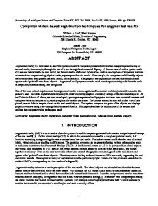
Our work aims at creating an unified framework connecting VR applications to heterogeneous devices and contexts in a simple, affordable and time-efficient way. . . . . Our contributions address several levels at the same time, ranging from hardware to user applications. . . . . . . . . . . . . . . . . . . . . . . . . . . . . . . . . . . . . . . Our unified framework allows 3D graphics abstraction among heterogeneous devices. The Mental Vision framework brings the necessary support to easily implement a conceptual idea into a concrete application. Notice how we first select the software (our solution, in this case) and then the device instead of the more common inverse approach. . . . . . . . . . . . . . . . . . . . . . . . . . . . . . . . . . . . . . . . . . . Through the Mental Vision framework we implement the best tradeoff we found among several constraints, often opposite, related to today’s computer graphics, virtual reality, research and education. . . . . . . . . . . . . . . . . . . . . . . . . . . . MVisio engine architecture results obtained through the multi-system approach: a same application (our robustness benchmark presented in chapter 6) rendering the same scenario on PDA, PC and CAVE. . . . . . . . . . . . . . . . . . . . . . . . . . MVisio engine architecture overview: users need to feed the software once and obtain support for three different devices for free. . . . . . . . . . . . . . . . . . . . . . . . . Our framework universe, with our direct contributions (green boxes) and related elements (grey). Our contributions range from hardware (with our custom CAVE system and wearable MR setup) to high-level applications (like pedagogical modules and tools), passing through a common denominator: the MVisio graphics engine. . . Related work schematic overview: bottom-up summary, ranging from hardware to high-level applications. . . . . . . . . . . . . . . . . . . . . . . . . . . . . . . . . . . . Nokia N95 and Apple IPhone, among the last generation handheld devices with embedded 3D acceleration hardware. . . . . . . . . . . . . . . . . . . . . . . . . . . . . Silicon Graphics O2 entry-level 3D workstation in 1996. . . . . . . . . . . . . . . . . Commodore Amiga 500, dream machine of � 80 featuring a multicore architecture with a Motorola 68000 main CPU at 7.14 MHz. Image source: Wikipedia . . . . . . . . . Barco multi-wall display framework. Image source: http://www.barco.com . . . . . . Portable mini Vee-CAVE. Source: http://planetjeff.net . . . . . . . . . . . . . . . . . Complex biomedical image rendered with a real-time implementation of a software ray-tracer. Source: http://www.visualbiotech.ch . . . . . . . . . . . . . . . . . . . . . Multimodal interaction with real-time 3D rendering on PDA [35]. . . . . . . . . . . . Crytek Crysis in game screen-shot, state-of-the-art of PC computer graphics in 2008. Autodesk 3D Studio Max, an example of widely used editor for 3D content. . . . . . VHD used for creating public demo showcases such as The Enigma of the Sphynx [1]. An example of (un)wearable AR setup. . . . . . . . . . . . . . . . . . . . . . . . . . . Wagner’s invisible train, a PDA-based video AR application adding a virtual train on top of a real wooden track [122]. . . . . . . . . . . . . . . . . . . . . . . . . . . . . . 15
20 21 27
28
30
31 32
33
36 38 39 40 41 42 45 46 48 50 51 53 54
4.1 4.2
Mental Vision platform architecture. . . . . . . . . . . . . . . . . . . . . . . . . . . . The MVisio graphics engine is the core entity of our work as well as the crossroad between hardware and user-level applications. . . . . . . . . . . . . . . . . . . . . . . 4.3 MVisio high-quality rendering with dynamic soft-shadowing, depth of field, highdynamic range, and bloom lighting on a modern desktop PC. . . . . . . . . . . . . . 4.4 MVisio class overview architecture. . . . . . . . . . . . . . . . . . . . . . . . . . . . . 4.5 Modules and tutorials are applications developed on top of the MVisio graphics engine. 4.6 A typical module template, inserted into a PowerPoint presentation like a dynamic slide, reusing the same layout and allowing interactive manipulations. . . . . . . . . 4.7 Students following as a teacher explains stereographics, and then reusing the module at home to implement red and blue stereo rendering on their practical projects based on MVisio. . . . . . . . . . . . . . . . . . . . . . . . . . . . . . . . . . . . . . . . . . 4.8 Camera handling, left image: third-person overview of the scene and rendering from the current camera viewpoint, right picture: camera targeted on a wall poster, as requested by the exercise. . . . . . . . . . . . . . . . . . . . . . . . . . . . . . . . . . 4.9 Levels affected by this section contributions. . . . . . . . . . . . . . . . . . . . . . . . 4.10 David vs Goliath: from a room sized virtual environment to a system fitting into a pocket, MVisio brings computer graphics seamlessly to both extents. Left: our wearable framework, right: an external overview of our CAVE. . . . . . . . . . . . . 4.11 3D complete scenes (with meshes, lights and textures) are easily exported and loaded into MVisio with just a few mouse clicks. . . . . . . . . . . . . . . . . . . . . . . . . 5.1 5.2 5.3 5.4 5.5
5.6
5.7 5.8 5.9 5.10 5.11 5.12 5.13 5.14
5.15
Multi-platform and multi-device support of MVisio, in this case running on Ubuntu Linux. . . . . . . . . . . . . . . . . . . . . . . . . . . . . . . . . . . . . . . . . . . . . MVisio multi-device rendering pipeline overview (grey boxes refer to elements not being directly part of our platform). . . . . . . . . . . . . . . . . . . . . . . . . . . . An example of a complex GUI created for the MHaptic editor (see 6.3.3.1), adding haptic properties to virtual objects. . . . . . . . . . . . . . . . . . . . . . . . . . . . . High-end terrain rendering using full shader-based optimizations for both speed and quality. . . . . . . . . . . . . . . . . . . . . . . . . . . . . . . . . . . . . . . . . . . . Hermite interpolation and Kochanek-Bartels spline module: listeners can bring their PDAs during lectures to directly try on their devices examples introduced by the teacher. . . . . . . . . . . . . . . . . . . . . . . . . . . . . . . . . . . . . . . . . . . . Spline generation modules using several techniques: mixing parabola (top left), Hermite interpolation (top right), Kochanek-Bartels (bottom left), and B´ezier (bottom right). . . . . . . . . . . . . . . . . . . . . . . . . . . . . . . . . . . . . . . . . . . . . 3D solid procedural generation: B´ezier patches (left) and sweeping techniques (right). Camera handling (top left), shading techniques (top right), and stereographic rendering modules. . . . . . . . . . . . . . . . . . . . . . . . . . . . . . . . . . . . . . . . . Animation modules: left on vertex skinning and key-framing, right on particle systems. Non calibrated walls: notice the glitch between the two walls (image center) and the grid not aligned for stereographic rendering (ghost effect on right side). . . . . . . . Walls after calibration, showing a correct alignment across sides and convergence for stereographic images. . . . . . . . . . . . . . . . . . . . . . . . . . . . . . . . . . . . . Red and blue stereo in our CAVE. . . . . . . . . . . . . . . . . . . . . . . . . . . . . Dual-projector assembly with shutters. . . . . . . . . . . . . . . . . . . . . . . . . . . Wearable system hardware overview, using a Dell Axim x50v connected to our custom VGA adapter (powered by a small battery pack) outputting power supply and video signal to the Liteye-500 see-through HMD. . . . . . . . . . . . . . . . . . . . . . . . . Bar scene rendered on the Dell Axim x50v. Image taken through the Liteye-500. . .
55 56 57 58 59 60
61
62 63
64 66
68 69 72 73
75
76 77 77 78 80 81 82 83
84 86
17
6.1
Mobile version of MVisio tested on a HTC Touch Cruise, using OpenGL| ES software rendering. . . . . . . . . . . . . . . . . . . . . . . . . . . . . . . . . . . . . . . . . . . 6.2 Mobile version of MVisio tested on a PDA (Dell Axim x50v), using OpenGL|ES hardware accelerated rendering. . . . . . . . . . . . . . . . . . . . . . . . . . . . . . . 6.3 PC version of MVisio tested on a desktop PC (NVidia Gefore 8800 GT, Intel Core2 Quad 2.4 GHz). . . . . . . . . . . . . . . . . . . . . . . . . . . . . . . . . . . . . . . . 6.4 CAVE version of MVisio tested on our low-cost system. The GUI is rendered on the server PC (bottom right image). . . . . . . . . . . . . . . . . . . . . . . . . . . . . . 6.5 User selecting a destination by manipulating the navigation software through a forearm controller. An extended version of our wearable MR setup is used to display 3D content and graphics user interfaces on the head-worn display (see [62]). . . . . . . . 6.6 DirectX SDK (left) vs Mental Vision (right) skinned animation sample: covering almost the same topic, DirectX source code is four times longer than our one and does not include editing functionalities. . . . . . . . . . . . . . . . . . . . . . . . . . 6.7 Curling and snooker simulations made by students, built on top of the MVisio engine. 6.8 MHaptic haptic engine using MVisio for visual rendering. . . . . . . . . . . . . . . . 6.9 MVisio used as visualization software for a PC-PDA vibrotactile jacket calibration application (from [11]). . . . . . . . . . . . . . . . . . . . . . . . . . . . . . . . . . . . 6.10 User testing the different reaching techniques in the CAVE. . . . . . . . . . . . . . . 6.11 Our CAVE used during young student visits to disseminate scientific technologies. . 6.12 MVisio portable V-CAVE setup (two walls in the corner of a white room, red and blue stereographic glasses), used for dissemination of 3D results on public conferences and demo showcases. . . . . . . . . . . . . . . . . . . . . . . . . . . . . . . . . . . . . A.1 A.2 A.3 A.4 A.5
MVisio SDK content overview. . . . . . . . . . . . . . Where to set a global path to your directory. . . . . . Directory settings in VS2005. . . . . . . . . . . . . . . Correct settings for a painless integration of MVisio... Your first application with MVisio (in debug mode). .
. . . . .
. . . . .
. . . . .
. . . . .
. . . . .
. . . . .
. . . . .
. . . . .
. . . . .
. . . . .
. . . . .
. . . . .
. . . . .
. . . . .
. . . . .
. . . . .
. . . . .
91 92 93 95
98
99 100 102 103 104 105
106 112 113 114 114 115
C.1 Microsoft Visual Studio multiple platform configuration: different target devices can be selected by simply changing the current project settings. . . . . . . . . . . . . . . 124
Chapter 1
Introduction Computer Graphics (CG) and Virtual Reality (VR) are sciences which have gained an increasing amount of popularity and applications during the last decade. Real-time advanced visualization features are now a common thing on mobile devices, home personal computers and still a key element of most VR applications. After almost half a century, we are closer to Sutherland’s initial vision about CG and VR [113]: as technology matures, both become better, cheaper, and more accessible. This increasing interest has also produced a very wide amount of both software and hardware technologies to support and improve creation of graphics applications and VR environments. Unfortunately, most of these innovations are often accessible only by specialists with a strong background knowledge in CG and VR programming, and through expensive, cumbersome devices and complex interfaces. VR applications require also a significant amount of time to be developed, because of the complexity introduced by the generation, adaptation and tuning of 3D content to fit into a specific visualization software under real-time constraints. Finally, VR is a complex and difficult topic to learn by itself, because of the points previously cited and also because of the heterogeneity of notions (mathematics, networking, physics, etc.) a developer usually needs to practice with before attempting to implement a complete Virtual Environment (VE). This chapter introduces our work context and the problematic addressed in this thesis, followed by our goals and proposed contributions, and concluded then by an overview of the content presented in this dissertation with its organization and conventions.
1.1
Context and motivations
Creating computer-generated images by means of IT technologies is a difficult and challenging task, even more when these images need to be generated dynamically, from 3D scenes, several times per second, and on market level machines. The heterogeneity of such machines, as well as their various software and computational features, make this task even more complicated when more than a single device or platform are aimed. VR and the need of visualization are also two inseparable entities: many of the applications involving a VE or simply virtual objects require a visualization device capable of rendering images in real-time and with a convincing graphics quality in situations ranging from big room-sized immersive devices to very compact wearable frameworks for mobile Mixed Reality (MR) or Augmented Reality (AR). For a VR developer, creating such systems from scratch may be a difficult job, requiring not only a large amount of time but also robust knowledge external to virtual reality, like computer graphics and network programming. Also, the cost itself of VR advanced systems (like multi-user immersive virtual environments or dedicated hardware) is pretty expensive and can not be easily afforded by everyone, mainly by students, teaching institutions and small research laboratories with limited budgets. Finally, VR-related frameworks are rarely 19
20
CHAPTER 1. INTRODUCTION
Figure 1.1: Our work aims at creating an unified framework connecting VR applications to heterogeneous devices and contexts in a simple, affordable and time-efficient way.
conceived for an immediate use through extremely intuitive interfaces, increasing time spent by programmers to concretely access the required functionalities and limiting the spread of applications of virtual reality to fields other than pure research or very restricted (and specialistic) areas. These points are among the main topics addressed in this thesis: simplifying access to 3D realtime visualization systems under each point of view, from the learning phase to final real applications, aiming at using at the same time affordable solutions (cost reasonable with acceptable quality/price constraints) through a very programmer-friendly and portable interface (see fig.1.1), making adoption of multi-device 3D CG a simpler task than in the past. Immersive environments (giving the feeling of being surrounded by an artificial 3D world) are a key feature required by many VR applications and are extremely difficult to simulate. Visual immersion needs specific, expensive and cumbersome hardware, such as head-mounted displays (HMDs), large displays or CAVE Automatic Virtual Environment (CAVE) systems. Due to the high cost of professional solutions and their complexity, the proliferation of such kind of environments is unfortunately limited to institutes or organizations able to pay and manage such facilities. A part of our work addressed the creation and simplification of an affordable but high-quality CAVE system. This opens access to such a device to students and arbitrary researchers in addition to CG or VR specialists, reducing learning curves, costs and complexity derived from the adoption of multi-display immersive devices. Mobility is one of the keywords of modern communication and IT-science. Users want to rely less and less on static or cumbersome solutions and prefer lightweight, dynamic and smart options when possible. A simple observation of the mobility-related technologies which have emerged in the last years is a good indicator of this trend: mobile phones and wireless networks, handheld gaming consoles, ubiquitous access to multimedia, etc. are day after day a more common and spread reality. CG and VR are also affected by this evolution: researches in wearable MR and AR have used the same technologies to build newer and more robust solutions than in the past. Unfortunately, the access to such frameworks is very technically demanding, because of the low resources available on handheld or mobile devices and the difficulty to find robust approaches being at the same time
1.2. CONTRIBUTIONS
21
Figure 1.2: Our contributions address several levels at the same time, ranging from hardware to user applications.
wearable, efficient and affordable. Another part of the work exposed in this thesis has been aimed at keeping and extending the same principles evoked above also to mobile devices and wearable frameworks. Despite the potential accessibility to cross-platform and multi-device CG functionalities, only very few applications take advantage from this option. Due to the heterogeneity of today’s devices and operating systems (more in chapter 3), this multiple approach should be the natural evolution of modern software, but it is not the case when a complex field like VR (requiring heavy 3D graphics rendering) is involved. This drawback is even more accentuated in fields like research and education, where it is extremely difficult to align everything on a single software and hardware system. Consequently, our goal has been the creation of a unique framework addressing all these issues at the same time and acting as a common denominator. We mainly oriented our solution towards needs and constraints of the educational and scientific community, notably reducing the learning curve and time required to create VEs on various devices and operating systems, limiting costs and complexity of immersive and wearable VR equipments, and improving understanding of CG and VR techniques by directly practicing with them. We called our framework Mental Vision, referring to the concept of being quickly and concretely able to create 3D graphics applications with more efficiency, thus spending more resources on ideas rather than technicalities required to set up a visualization system.
1.2
Contributions
In this thesis we propose our approach to solve the points evoked above, by creating a solution intended to be at the same time very intuitive, complete and affordable for learning, creating and practicing with VR and CG in heterogeneous contexts, operating systems and devices. This work brings contributions at various aspects and levels, ranging from low-level software and hardware issues (as we did with the creation of a low-cost CAVE system, from its hardware to its software) to high-level applications conceived for educational and development goals (see image 1.2). For sake of clarity, we regrouped and summarized our contributions into three main topics. The most important one is a multi-platform and multi-device 3D graphics engine we created, called MVisio. Our graphics engine is a piece of software aiming at simplicity and portability: as
CHAPTER 1. INTRODUCTION
22
far as we know, it is the only 3D graphics engine running the same way and through the same interface on mobile devices, personal computers and CAVE systems, thus a concrete application of the concept “3D graphics from your pocket to your CAVE”. MVisio is the core software of our platform, interfacing hardware with software, low-level Graphics Processing Units (GPUs) accessibility to pedagogical applications, etc. It is also widely used in many everyday’s activities of our laboratory, from lectures and practicals to student and scientific projects. On a lower level (closer to hardware and middleware) we addressed our researches towards usability and spread of advanced VR frameworks, going simultaneously into two opposite directions: a room-sized CAVE system and a wearable mobile one. In this thesis we describe how we managed to develop a four-sides CAVE setup aiming at reducing costs and complexity of the framework by using market level hardware and smart software techniques to get rid of the lack of precision introduced by inexpensive material. By adopting the same principle, we built a lightweight wearable system featuring onboard rendered 3D images, using off the shelf hardware to reduce overall costs. In both cases, functionalities offered by these devices are accessed through MVisio. On a higher level (application development and distribution) we made a set of pedagogical modules for teaching and learning of CG and VR concepts and to familiarize with the use of the MVisio engine. These modules are built on top of the MVisio engine and act at the same time as teaching applications and demonstrations/tutorials of the different features of our software. Besides modules, we also developed a series of additional tools to speedup and simplify accessibility to 3D contents (like file exporters/converters, tutorials, wizard classes, etc.). We largely tested and used our contributions in different contexts and scenarios, ranging from academic to industrial ones: the case studies on chapter 6 validate our approach and show how our ideas addressed and found an answer to specific needs that were not satisfied by other existing solutions. We introduced our first results on the Mental Vision platform in [82]. In [83] we separately described the mobile aspects of the platform, while in [81] we published our extended version working on CAVE systems. In [84] we summarized details and results obtained by experimenting and using our framework on classes and research projects. Our work has been used and cited in many projects and scientific publications: chapter 6 refers to a selection of them as evaluation.
1.3
Organization of this thesis
This dissertation is structured in the following way: first an introduction to the topic is given in this chapter (chapter 1), briefly summarizing context and goals of the work we did. Chapter 2 contains the detailed motivations and objectives of this thesis, progressively dealt in the following chapters. From this chapter on and for exposition clarity, we regrouped our contributions into three categories: the MVisio graphics engine, high-end application development with pedagogical modules and other tools, and hardware/software setup of the low-cost CAVE and wearable system. State-of-the-art is presented in chapter 3. Despite our research project started in year 2005, we included also more recent contributions in fields related to our one to show how other solutions have been proposed to address our same issues. Nevertheless, our approach features unique characteristics that will be illustrated along this text. Because of the wideness of elements we covered during our project, chapter 3 is divided into two main sections reporting most relevant contributions on hardware available for CG and VR (to give a overview of the current universe of 3D graphics devices our approach has been based on), and software to access and use it. Our contribution main elements are first conceptually explained in chapter 4, with a generic theoretical overview of our solution, exposing features and global architecture of the whole system. In chapter 5 we do the same but focusing mainly on the effective implementation of the ideas and architectures previously exposed, including examples and technical details.
1.4. CONVENTIONS
23
Chapter 6 contains evaluations of our platform covering in vitro tests, benchmarks, case studies and discussions about concrete applications developed through our software, while chapter 7 concludes this dissertation with final remarks and future perspectives. This text is then completed by several appendices containing additional details like application source code examples, file format specifications, etc.
1.4
Conventions
In this thesis we refer to several intrinsic CG and VR concepts that may lead to misunderstandings according to the different nuances readers could have of their significations. For this reason, we added a glossary to this text as appendix at page 133. For clarity, these concepts are written with first letter capital at their first occurrence in a chapter, followed by their abbreviations in parenthesis, like Mixed Reality (MR) or Virtual Environment (VE). The abbreviated form or extended name but in lowercase will then be used for the rest of each chapter. This glossary is available in appendix D. In this text we also refer many times to the term user. According to the context, this term can assume a different connotation. Our main entity (the MVisio graphics engine) is intended for programmers, so the term user related to this topic identifies an audience of more or less expert developers, ranging from students with a basic background in programming to IT-Science experts, passing through occasional developers (like mathematicians, physicians or other kinds of researchers with some coding knowledge and requiring a system like ours). The term user assumes a wider and more generic meaning when applied to visitors experiencing demonstrations of our CAVE, or using our wearable system. Examples requiring to show details about programming and source code are written and summarized directly in their native languages. We preferred not to resort to pseudo-code in order to show real utilizations of our software that may be used later by the reader to directly try our platform. Also, simplicity and intuitiveness being an intrinsic part of our work, these examples are intended as concrete demonstrations of our system interface and should be clear enough for any reader with basic programming skills. This way, less important or irrelevant parts are cited and summarized as comments directly in the code snippets, like in the following example: // Source code template used in this thesis: bool renderMesh() { // Bind materials and lights // ... glBegin(GL_TRIANGLES); // Pass the whole geometry here glVertex3f(x1, y1, z1); glVertex3f(x2, y2, z3); glVertex3f(x3, y2, z3); // ... glEnd(); return true; } For a better reading of this document for non-programmers, such examples are kept apart from the main text into appendix C and referred through our work, in order not to divert attention from conceptual explanations to more technical concepts.
24
CHAPTER 1. INTRODUCTION
Scientific references to papers, journals, proceedings, workshops, etc. are cited with numbers (like [17]) and detailed in the bibliography at the end of this dissertation at page 137. References to web-sites and web-pages are directly inserted in the text as footnotes. URLs have been checked for validity and updated in March 2009. Chapters are written as stand alone as possible, in order to give them sense and improve their comprehension without reading the whole text. Therefore, some concepts may appear repeated or summarized more than once.
Chapter 2
Proposal This chapter is about the different issues we addressed in our work, and ideas and contributions we introduced to find a solution to them. All these contributions have been concretely assembled in what we called the Mental Vision platform, made of an intuitive and multi-system 2D/3D graphics engine, a set of pedagogical applications to improve understandings of Computer Graphics (CG) and Virtual Reality (VR) techniques (as well as the utilization of the graphics engine itself), and corollary components like a low-cost CAVE environment and a lightweight wearable mobile graphics setup. While this chapter is mainly a conceptual overview of the motivations and ideas of this thesis, next ones will develop in detail the different topics evoked in the following sections.
2.1
Considerations
In this section we summarize current issues related to specific topics of the different areas of VR and CG like accessibility, immersion, education and portability of today’s hardware and software (a 360 degrees overview of the situation is given in chapter 3). The extremely wide horizon of applications and contexts related to real-time computer graphics motivated us to focus our scope on scientific and pedagogical fields, as they are the ones we deal with daily. Nevertheless, most of the recurrent needs of these two fields are shared also by other contexts like industrial standards, looking at optimizing the tradeoff between results and time required, or video-games, requiring nicer graphics effects with higher performances as well as targeting a very heterogeneous hardware universe.
2.1.1
Accessibility, immersion and portability
CG and VR need complex software giving access to advanced functionalities required to visualize objects and build 3D interactive scenarios. This kind of software is very diversified and often oriented towards a specific field (such as gaming, Computer-Aided Design (CAD), simulation, etc.), a selected user pool with specific base skills and background (industry developers, students, architects, etc.), and platform (Windows, Unix-based systems, MacOS, mobile or desktop machines, etc.). The adoption of one of these tools extends its limitations to the users who selected to use it, usually reducing future perspectives and modifications. These things happen quite regularly to student and research works, more affected by lack of strict scheduling and formal planning than industrial standards [29]. Computer screens and desktop or laptop PCs are widely used for visualization purposes but are not the only displaying devices, mainly in the case of scientific, medical or immersive imaging. VR also often requires the use of specific, less common and not widely available devices, improving complexity related to portability and accessibility. Also both scientists and students may work on 25
CHAPTER 2. PROPOSAL
26
very different hardware and software in their projects. A unique framework allowing them to access rendering functionalities in a same (easy) way various operating systems and devices is a strong advantage when compared to other options. Visual immersion then needs specific, expensive and cumbersome hardware, such as head-mounted displays (HMDs), large displays or CAVE systems [112]. HMDs offer a good level of immersion, but often suffer from a small field of view and isolate the user and his/her body both from the real and the virtual world [20]. Spatially Immersive Displays (SIDs), like wall-displays and CAVEs, have the advantage of being multi-user, to allow persons to be physically within the Virtual Environment (VE) and feature a wide field of view. Many studies [118] [10] showed that devices based on large displays offer a better immersion and cognitive interaction with a virtual 3D environment. Unfortunately, due to the high cost of professional solutions and their complexity, the proliferation of such kinds of environments is limited to institutes or organizations able to pay and manage such equipments.
2.1.2
Education, practice and user-friendliness
During VR courses practical sessions, students should focus their attention on the orchestration of different aspects in order to create robust and convincing scenarios, affecting not only visual components. It is up to teachers to offer them all the required tools to do that without distractions from their main goal. VR researchers also should spend less time on the learning curve required by accessory graphics Application Programming Interfaces (APIs), which are only one of the instruments they need to fulfill their objectives. The choice of these learning and research tools is unfortunately not an easy task, since many criteria have to be considered carefully: 1. These tools have to be extremely easy to use and robust, in order to let users immediately start working on their VR projects. Now, if the goal of a user is to benefit of some existing device (a CAVE, a PC) and software (a VR environment Software Development Kit (SDK)), this software should take care of everything in the easiest possible way, freeing the user from all the side aspects required and letting him/her deal directly with his/her goal. 2. Tools should access VR specific devices (like HMDs, CAVEs or mobile frameworks) and let users switching between them seamlessly, in order to simplify and support experience gathering and experimentations with heterogeneous hardware platforms. 3. Tools have to be versatile enough to give students the opportunity to experience their own way, researchers to easily and rapidly achieve their goals, and teachers and assistants to reuse them in their classes (researchers, teachers and assistants being often the same persons like in our laboratory). 4. This software should be platform independent, as both students and researchers may work on various and less common configurations, or have different operating systems at home and at school/work. Software should also be smart enough to adapt itself to run efficiently on more or less performing and recent hardware (again, students may have very different machines). 5. Teaching tools should be free (software side) and low-cost (hardware side), dramatically reducing fees, mainly due to the relative low budget available by teaching institutions. Tools should give students a real opportunity to be used for home work or personal projects. 6. Software should be as modern as possible (as CG related hardware evolves very quickly). Students are fashioned by recent movies and video-games: offering them tools generating modern game-like images is a potential motivator [12].
2.2. ISSUES ADDRESSED
27
The coherence factor should also be taken into account: by coherence we mean that the entire teaching pipeline (from lectures to practical projects) looks robust, logical and consequential. By using the same tools for theory and practice, courses reduce the patchwork-effect that classes suffer from being made by largely using (copy/pasting) a plethora of different software into a same course. This heterogeneity may be enriching in some cases but more often leads to confusion and weakens the class understandability and teacher skill to clearly bring the audience to a goal.
2.2
Issues addressed
This section mirrors the previous one and summarizes our suggestions and contributions with regards to the issues previously enumerated.
2.2.1
Accessibility, immersion and portability
We organized our Mental Vision framework in order for it to be a generic, unified graphics solution non limited to a selected, specific user pool nor to a specific architecture, operating system or device. The graphics engine used in our platform, for example, is capable of rendering real-time images on PDAs, mobile phones, laptops, desktop PCs and CAVE systems. Despite that our targeted categories are mainly science and education, our contributions are not restricted to this audience: we decided to use simplicity as the common denominator among different user needs. In fact an easy to use, accessible tool can be used by both new and advanced users, when the opposite is not always true. Simplicity and intuitiveness are also overall welcomed characteristics, by any kind of user. We then extended this accessibility friendliness to the multi-platform aspect of our contribution too, making the transition from a system to another (like from PC to PDA, or from PC to CAVE) as automatic and transparent as possible: multi-device support can be considered for free when using our platform, as the software itself adapts the content to get the best out of the system it is running on (see fig.2.1).
Figure 2.1: Our unified framework allows 3D graphics abstraction among heterogeneous devices. We addressed the problem of expensive immersive devices integrating a high quality CAVE system using standard market products and internally developed software. Despite this, we built a very flexible, robust, high quality and fast CAVE environment, featuring stereographic rendering, a good calibration system for walls and sensors, head-tracking and last generation graphics comparable to recent video-game engines. We kept accessibility to our CAVE straightforward and fully compatible with other devices like PCs or mobile ones. In brief the advantages of our unified framework:
CHAPTER 2. PROPOSAL
28
1. Users do not need to learn more than one API or to fork their projects into sub-components according to the context (DRY rule: don’t repeat yourself [45]). 2. The learning curve to access functionalities (either for basic/first utilizations or advanced needs) is optimized to reduce time and maximize results with less work, through a very simple interface (KISS rule: keep it short and simple [40]). 3. Switching from a platform or device to another one is just a matter of a few moments, thus improving fruition and experimentation on other platforms/devices, previously neglected because of porting time constraints or the need to learn a different API for each system. 4. Users can develop and test graphics applications requiring specific hardware (CAVEs, HMDs, mobile frameworks) on their desktop PCs, seamlessly switching to the designated device when available later.
2.2.2
Education, practice and user-friendliness
Mental Vision has been created by mainly targeting the needs and constraints of the educational and scientific community, notably reducing the learning curve and time required to create virtual environments, limiting the cost of immersive or wearable frameworks without compromising their quality, and improving understanding of VR concepts and techniques by directly practicing with them. Moreover, such a framework has been designed to fit into a wide range of heterogeneous devices, ranging from low-end student PCs through mobile devices up to CAVEs [19], across different operating systems and hardware setups (see fig. 2.2).
Figure 2.2: The Mental Vision framework brings the necessary support to easily implement a conceptual idea into a concrete application. Notice how we first select the software (our solution, in this case) and then the device instead of the more common inverse approach. To avoid the patchwork-like problems cited above, we have created a set of software tools to improve the quality and comprehension of our CG and VR courses and to simplify and unify student works, offering them a simple but complete and robust 3D graphics engine (MVisio) to use during practical sessions and projects. To break the lack of dynamism and interactivity given by slides, images and videos during teaching classes, we have developed a set of applications featuring real-time
2.3. THE MENTAL VISION PLATFORM OVERVIEW
29
and dynamic demonstrations of the presented topics. Our demonstrators allow students to directly act on parameters and algorithms, offering a dynamic cause-effect explanation, unavailable through static methods (blackboard schematics, formulas, images, etc.). These demonstrators are a set of interactive compact applications (modules) which show in a clear and simplified way complex notions like sweeping surfaces, B´ezier patches, camera clipping planes, etc. These modules are extremely lightweight software which can seamlessly be distributed over the internet, included in presentations or executed on handheld devices. In fact, thanks to their versatility, they can also be executed on laptops or personal digital assistants, thus be brought and used directly during lectures. All these tools, ranging from the 3D rendering engine to pedagogical modules, extended also to the design of a low-cost CAVE and a mobile wearable graphics setup, are the different concrete components of our contribution. We assembled these entities in the Mental Vision platform, progressively described in the following sections and chapters.
2.3
The Mental Vision platform overview
Mental Vision is a CG and VR framework oriented towards education and scientific research needs. Our work is divided into three main entities: the 3D graphics engine itself (referred to as the Mental Vision engine or in its brief form MVisio 3D graphics engine), the pedagogical tools (like modules and tutorials) that rely on MVisio, and hardware tools (a low-cost CAVE system and a wearable 3D Mixed Reality (MR) setup) and corollary software (plugins, converters). We summarized our work into these three containers in order to simplify understanding and exposition of our contributions during the rest of this thesis. We decided to create our own system after comparing different existing solutions without finding a perfect one satisfying all our constraints (fig.2.3), some of them being also contradictory and opposed (like having low-cost immersive setups, or user friendly modern and advanced CG). We can summarize the main characteristics of our contributions into several points, described hereafter.
2.3.1
Portability
Today’s IT Science is a matter of heterogeneous operating systems and computing devices. Every person may be confronted with a Apple MacOS machine at home, a Windows Mobile based mobile phone in their pockets and a Linux system at work each day. Students and researchers also fall into this category, having a wide set of different, more or less recent and more or less heterogeneous machines and software at home, laboratories or school. We applied this concept to devices, allowing users to develop 3D-based applications on PC that can be ported on handheld or immersive devices later, simplifying software development and debugging. We decided to make our framework not only multi-platform (running under Windows and Linux-based systems), but also multi-device, seamlessly accessing mobile devices (running under Windows Mobile 4 or newer) and CAVE systems (over a multi-PC distributed network architecture) through the same API. Thanks to this approach, students and researchers can work in their office, school and at home on different machines but still accessing the same functionalities through the same way, without having to write different code paths or manage more solutions concurrently (see fig. 2.4).
2.3.2
Robustness and application deployability
An unavoidable problem introduced by cross-platform and -device architectures is to assure that users can effectively obtain the same results on different machines without extra cares, as done by the RAGE engine through the use of Java in [66]. Due to students and researchers needs to run their projects on different PCs (classrooms, project evaluations, home PCs, demo scenes, colleagues
CHAPTER 2. PROPOSAL
30
Figure 2.3: Through the Mental Vision framework we implement the best tradeoff we found among several constraints, often opposite, related to today’s computer graphics, virtual reality, research and education.
computers or laboratory machines), and because of the need to be able to release or publish applications intended to run on any arbitrary PC (as we did in the case of our pedagogical modules), the framework itself should be compact and robust enough to reduce external dependencies, conflicts and sizes, but still support compatibility between recent and older machines. We reduced interface sizes and external dependencies (like to the Java platform) by creating instances of our framework running natively on the different supported systems (two versions for PCs, Windows and Linux, two versions for Windows Mobile systems, one using hardware acceleration and one generic in software mode, and a version for CAVE). The main core of our platform weighs less than 1 MB and is ideal for online downloads or storage on handheld devices. Our engine also automatically detects the power of the machine it is running on and activates/deactivates options and alternate functionalities to improve graphics rendering or performances.
2.3.3
User-friendliness
Real-time 3D computer graphics environments are complex software requiring good knowledge and familiarity with low-level programming and libraries featuring sophisticated interfaces, often optimized for speed but detrimental for clarity and simple utilization. Graphics engines are generally also large frameworks with consequent documentation, requiring many days, weeks or months to become comfortable with. With Mental Vision we believe that we reduced the learning curve and time required to create applications, and improved understanding of VR concepts and techniques by directly practicing with
2.3. THE MENTAL VISION PLATFORM OVERVIEW
31
Figure 2.4: MVisio engine architecture results obtained through the multi-system approach: a same application (our robustness benchmark presented in chapter 6) rendering the same scenario on PDA, PC and CAVE.
them through pedagogical modules. Building a real-time 3D environment through Mental Vision is a matter of minutes, thanks to the light interface our framework exposes and working examples available by reading pedagogical modules source code. Creating a graphic context, loading and displaying a scene can be done in few lines of code (for a working example see appendix C.1). Unnecessary parameters, advanced options and low-level access to 3D functionalities are always available but not required for new or basic users. With Mental Vision it is possible to immediately obtain results and directly see the impact of your modifications. Porting an MVisio-based application on different platforms (like from PC to handheld devices or CAVEs) is also a matter or few minutes, thanks to the framework automatically adapting itself, data loading and (when required) networking to make the transition as simple, transparent and immediate as possible. With Mental Vision users can focus on their goals without wasting time on the tools required to achieve them.
2.3.4
Completeness
Computer graphics and virtual reality are fields requiring many things at the same time, ranging from 3D models and tools to create them to graphics user interfaces to acquire user inputs at runtime or quickly change some parameters. The Mental Vision platform addresses all the pipeline required to setup a virtual environment: corollary tools allow users to easily export 3D data from external software and to reuse them in ours. The graphics engine features a simple but complete graphics user interface system offering the same functionalities on mobile devices, PC and CAVEs. Finally, pedagogical modules act as starting examples to create new projects with. Some of them also act as editor to export particle systems or short animations to our framework. All these things make Mental Vision a platform that can efficiently be deployed on real projects, as we show in chapter 6.
CHAPTER 2. PROPOSAL
32
Figure 2.5: MVisio engine architecture overview: users need to feed the software once and obtain support for three different devices for free.
2.3.5
Cost efficiency
Despite the mass introduction of CG dedicated hardware, high-end 3D immersive or mobile systems are still very expensive and require specific software. With our framework, independent from costly software and hardware, and aimed at educational and scientific contexts (often very budget-limited), we offer a robust solution under affordable budget constraints. We developed a CAVE system by using common hardware and, thanks to our software, we tweaked the hardware quality gap between professional and home-made solutions in an efficient way. We also developed a wearable mixed reality framework, very lightweight and using common handheld devices but still offering interesting features under reasonable limitations. Both these setups are based on the MVisio graphics engine.
2.3.6
Modern and updated
3D computer graphics are evolving very quickly, making today’s technologies to become old and obsolete after a short period of time. By looking at available professional games and CAD engines, we can estimate a graphics engine life cycle of about five years, if well conceived and featuring some regular updates as well as an open architecture allowing an easy integration of new elements and features when necessary. Under MVisio, users can simply add their own new shaders and create new classes directly accessing low-level CG libraries. New objects created this way, by means of class derivation as exposed in appendix C.3, automatically pass through the engine pipeline, considerably reducing the amount of time and knowledge required to add new complex entities to the system.
2.3.7
VR aware
Virtual reality is a field very often needing specific devices, like HMDs, CAVEs, or haptic devices. Our framework exposes a series of functionalities to directly use this hardware or to simplify their interfacing. For example, stereographic rendering is directly supported on CAVE and can be easily activated on a PC to output images to an head-mounted display.
2.4. CONCLUSION
2.4
33
Conclusion
In the literature and common belief, virtual reality and computer graphics are often put together and somewhat considered different aspects of a same thing. In the educational area, VR classes merge into CG courses and mix tools and instruments created for one field in the other one, and vice versa. Users requiring some real-time 3D graphics in their projects need to learn how to use usually complex software and APIs which are time-expensive to handle, or even to create a solution from scratch, diverting their attention and resources from their objectives. In a more generic formulation: CG tools should answer a need while releasing the user from a weight, and not be an additional obstacle. Also, relying on third-party software is almost unavoidable when users need to deal with projects requiring real-time visualization and animation of virtual humans or complex models with advanced shading techniques (like shadowing or bloom lighting). In this work we expose in detail each step of the creation and design of the Mental Vision framework, comparing our approach against other similar ones, and we illustrate a series of case studies of concrete utilizations and applications developed through the use of our framework in toto, pointing out the contributions brought. In this dissertation we insisted in making complex things easier and more affordable for users, in order to widen the fruition and potential applications of VRoriented technologies. Our experience with students and researchers has shown that this approach effectively responds to needs which are not only welcomed, but also required. To summarize, our work has been focused on these main topics: the designing and creation of a cross-platform and -device 3D real-time visualization system, the development of an extremely easy, compact and user-friendly interface to access and manage it, the design of learning applications to practice with CG notions and our engine features, and the construction of high-level VR setups by (re)using widely available components in order to make them as affordable as possible. As concrete application scenarios, as well as case studies, we used the teaching of VR itself and research projects related to this topic. These are perfect cases where IT students and researchers often need to create complex and varied projects in a short amount of time, thus making them an ideal population for testing our approach.
Figure 2.6: Our framework universe, with our direct contributions (green boxes) and related elements (grey). Our contributions range from hardware (with our custom CAVE system and wearable MR setup) to high-level applications (like pedagogical modules and tools), passing through a common denominator: the MVisio graphics engine. Due to the wide field aimed at by our goals, our contributions affect IT-Science at different levels (fig. 2.6). In the next chapter we make an overview of these different levels, in order to give the
34
CHAPTER 2. PROPOSAL
reader a better and complete understanding of the context wherein we worked and decided to invest our researches. The three main entities of the Mental Vision framework are then described in detail in the following chapters: the multi-platform, multi-device 3D graphics engine MVisio (see 4.1), tools ranging from pedagogical interactive demonstrators to tutorials (see 4.2), and our low-cost CAVE, wearable MR system and additional helpers (see 4.3).
Chapter 3
State-of-the-art and related work A wide effort has been invested during the last years into the production of tools to standardize and simplify access to 3D visual contents. Industry, researchers and the open-source community released a large amount of chipsets, graphics cards, drivers, libraries, platforms and similar to extend concrete and potential applications of Computer Graphics (CG), covering almost each possible device, operating system and context. Our motivations and contributions find origins and take a place at several levels into this universe. First, an overview of the 3D hardware evolution and availability is given, since our platform has been created as a consequence of this heterogeneity, in order to propose a common thread keeping under the same roof a coherent access to 3D high-level functionalities on handheld devices and home computers, as well as CAVE systems and Personal Digital Assistants (PDAs) connected to head-mounted displays. The first part of this chapter is then consecrated on devices and hardware technologies, so as to give to the reader a better understanding and overview on the state-of-the-art graphics developers have to face with to successfully implement a working 3D environment. This chapter blends then progressively to software and research aspects, by first indicating existing ways to access 3D features from a programming point of view, up to higher-level applications on teaching of CG themselves and scientific utilizations of Virtual Reality (VR) on research projects. To keep a good readability of this chapter, we grouped the different categories into separated sections, ranging from hardware 3D devices to educational CG frameworks. For each topic we summarized most notable contributions related with our work. Despite this thesis started in year 2005, we cite also more recent researches since some of them, while taking different approaches, share parts of our intentions. We structured this chapter in a vertical bottom-top order, going from low-level IT elements (closer to the hardware) to higher level applications as depicted in fig. 3.1. As already briefly introduced in the previous chapter, our contributions affect CG and VR at these three levels.
3.1
Hardware for 3D
This section contains an overview of the hardware we targeted in our platform, explicitly or potentially useable for real-time computer graphics. This section is divided into four main subsections, covering mobile devices (3.1.1), personal computers (3.1.2), CAVE systems (3.1.3), and virtual reality equipments (3.1.4).
3.1.1
Mobile devices
Mobile devices such as mobile phones, handheld gaming consoles or mini PCs are new hybrid platforms bringing multimedia into our daily life [67]. Among their functionalities, we are mainly 35
CHAPTER 3. STATE-OF-THE-ART AND RELATED WORK
36
Figure 3.1: Related work schematic overview: bottom-up summary, ranging from hardware to highlevel applications.
interested by their computational features supporting CG and connectivity to other machines or external devices. In this subsection we explore the current state-of-the-art of mobile devices capable of real-time 3D CG and potentially useable in VR contexts. We emphasize on devices best suited for generating real-time graphics according to the constraints of scientific and educational needs, as well as their sizes and weight, in order to fit into mobile graphics contexts (like mobile Augmented Reality (AR) or Mixed Reality (MR) scenarios), without sacrificing rendering quality and comfort.
3.1.1.1
Gaming devices
The entertainment industry is among the first producers and innovators of mobile CG-enabled devices. Handheld consoles like Sony PlayStation Portable1 (PSP) or Nintendo GameBoy DualScreen2 (DS) offer a great 3D rendering and computational power in compact sizes, weight and affordable prices. These devices risen interest also in the scientific community for developing specific applications not only related to the gaming scene, like software to aid disable people [108]. Unfortunately these platforms are closed systems extremely entertainment-oriented and difficulty usable out of their original context. They use ad hoc protocols and Application Programming Interfaces (APIs) which are often released only to business partners, and lack connectivity to external devices (like Head-Mounted Displays (HMD) or GPS) to create extended frameworks using these low-cost devices as core units. Moreover, the game industry does not seem interested in deepen their hardware towards AR or MR, thus the absence of inexpensive gaming devices natively suited for these purposes. A few exceptions exist, like Sony Eyetoy3 used in [24], or have existed, like Nintendo Virtual Boy4 in 1995, featuring a HMD-like, although not wearable, monochromatic stereographic display. 1 http://www.us.playstation.com/PSP 2 http://www.nintendo.com/ds 3 http://www.eyetoy.com
4 http://en.wikipedia.org/wiki/Nintendo_Virtual_Boy
3.1. HARDWARE FOR 3D
3.1.1.2
37
Personal Digital Assistants (PDAs)
Personal Digital Assistans (PDAs or palmtops), originally conceived as evolution of handheld agendas, have greatly grown in versatility in the last few years and they are now more and more getting closer to a compact PC. PDAs potential has been rapidly recognized and used by the scientific community as a valid option for mobile and ubiquitous computing, including 3D graphics (like in [131]). In fact, the current generation features a powerful RISC microprocessor (with speeds ranging from 400 to 700 MHz), WiFi integrated adapters, 640x480 VGA displays, audio cards and a good set of expansion tools like compact cameras, GPS and GSM adapters, micro hard-disks, USB/Bluetooth interfaces and external display outputs. Mobile by definition, PDAs are an excellent compromise between the computational power offered by notebooks and a truly wearable and lightweight device: they are less shock sensitive and do not need special cooling cares. Furthermore, they are cheaper than a laptop PC and their batteries last longer. Some of them are also equipped with a 2D or even a 3D acceleration chip, like Dell Axim x50v5 featuring a PowerVR MBX Lite6 graphics processor (widely used like in [93], [48] and [59]). Thanks to the heavy improvements on the software side, PDAs are today reasonably easy to program and use in new domains far from the simple schedule or address book they were originally conceived for. PDAs run on specific operating systems like Windows Mobile or Symbian, thus reducing their compatibility with standard home PCs and requiring ad hoc software solutions. 3.1.1.3
Ultra-Mobile PCs
Ultra-Mobile Personal Computers (UMPCs) are somehow the chain link between PDAs and notebooks. They look like a more compact and lightweight laptop featuring less power but still using the same PC architecture and operating systems. UMPCs have the advantage of being more mobile and wearable than a standard notebook but suffer also from the same constraints about shock sensitivity and overheating if not correctly cooled. On the other hand, UMPCs are less limited than a PDA and offer a bigger computational power and wider connectivity for external displays (like HMDs) and devices. UMPCs also run on the same operating systems available on home PCs, reducing the complexity of application porting among different devices (as used in [125]). Models like Sony UX707 and Asus EEE8 offer about 1 GHz power with basic 3D hardware acceleration in a compact and robust case, ideal for mobile contexts as we experienced in [85] on a wearable 3D guidance system. 3.1.1.4
Mobile phones
Mobile phones have known a wide evolution during the past years. It is today almost impossible to find a model without a color display, a multi-tone audio device and a digital camera. Modern mobile phones allow programmers to create custom applications to run onto, based on standards like Java or native programming in C/C++. Some models also run on exactly the same operating systems used on PDAs, thus allowing an easy cross-platform operability among heterogeneous mobile devices. In fact the barrier among PDAs, UMPCs and mobile phones is so tiny that models referring to one of these families could easily fit into another category. Modern mobile phones enable to play videogames, like on gaming consoles, in products such as Nokia NGage9 , Nokia N95 or the Apple IPhone10 (see figure 3.2). Some models also show advanced 3D rendering capabilities thanks to the new generations of mobile chips for hardware CG acceleration, like NVidia GoForce11 or ATI Imageon12 . For example, Nokia N95 supports direct hardware acceleration via Java and OpenGL|ES 5 http://www.dell.com/content/topics/segtopic.aspx/brand/axim_x50?c=us&l=en&s=gen 6 http://www.powervr.com
7 http://www.sonystyle.com 8 http://eeepc.asus.com 9 http://www.nokia.com
10 http://www.apple.com
11 http://www.nvidia.com 12 http://www.ati.com
CHAPTER 3. STATE-OF-THE-ART AND RELATED WORK
38
Figure 3.2: Nokia N95 and Apple IPhone, among the last generation handheld devices with embedded 3D acceleration hardware.
(see subsections 3.2.1.4 and 3.2.1.2), enabling interesting rendering capabilities on a very small mobile phone. Mobile phones are aimed by many research projects as a lightweight mobile device with interesting computational power to allow ubiquitous computing on several scenarios, like in [13] for a location based service with 3D feedback, [31] for experiencing new controller interfaces for 3D environments, or [37] for augmented reality.
3.1.2
Personal Computers
In this section we summarize the recent evolutions of real-time 3D rendering capabilities for microcomputers. Thanks to the innovations brought by the entertainment industry, today’s desktop PCs are extremely competitive CG machines with accessible prices. 3.1.2.1
Ad hoc workstations
Due to the heavy load of computations required to perform real-time CG, 3D rendering has been restricted for a long time only to owners of dedicated machines conceived to excel in this specific domain. These computers were very expensive and their spread limited to professionals only. Silicon Graphics13 (SGI) was among the most prolific and known sellers of CG computers in the nineties, like IRIS (Integrated Raster Imaging System) series, Indy/O2 entry-level workstations (see fig. 3.3), or Altix (performance comparison showed in [99]). Silicon Graphics was a pioneer of real-time CG commercially available, creating in 1980 the first 3D graphics workstation with a 3D chip, accelerated framebuffers and 3D primitives as well as Z-Buffer for hidden face removal. In 1984, IRIS 1400 integrated custom VLSI graphics accelerators (GeometryEngines) and a framebuffer. The IRIS 1400 is referred as the first generation of modern graphics systems, featuring flat shading polygons and used for Computer-Aided Design (CAD) applications and scientific visualization [7]. The first second-generation graphics workstation was the Hewlett-Packard SRX, followed by the Silicon Graphics GT, breaking for the first-time the 100� 000 polygons per second barrier, featuring also Gouraud-shaded surfaces [32] from Phong lighting [86] computed vertices (similarly to the OpenGL fixed function pipeline). Third generation appeared late in 1992, featuring hardware texture mapping and anti-aliasing with the Silicon Graphics RealityEngine (1994). On the game industry, Nintendo sold the N64 13 http://www.sgi.com/
3.1. HARDWARE FOR 3D
39
Figure 3.3: Silicon Graphics O2 entry-level 3D workstation in 1996.
console providing RealityEngine-like graphics for the masses. During early � 90, home desktop PCs were only capable of basic software 3D rendering performed on generic CPUs. The introduction of inexpensive graphics accelerators for desktop PCs (see next subsection) reduced the market of specific CG computers and opened high-quality real-time CG to any budget. 3.1.2.2
Graphics accelerators
As stated in the previous section, 3D hardware accelerated rendering was available only on highend dedicated workstations with prohibitive costs. This trend has been radically changed by the introduction on the customer market of 3D accelerators with reasonable prices for PCs, and became a standard in the late nineties. The first generation of PC Graphics Processing Units (GPUs) was basically an improved 2D (bitmap, GUI) accelerator chip with some 3D features added to the core (Matrox14 Mystique, S315 ViRGE, ATI16 Rage) or pure 3D only, without any 2D support (like 3dfx Voodoo) [65]. Only later generations integrated at the same time into an unique board video, 2D and 3D acceleration. Typically, these graphics accelerators come as an extension card to put into a desktop PC. 3D graphics cards are similar to a PC into a PC, featuring a GPU processor based on Single Instruction Multiple Data (SIMD) architectures and fast embedded memory for textures and geometries. The dedicated processor is optimized for parallelization and floating points computations of CG algorithms, releasing the general purpose CPU from doing that. Historically, one of the first home computers integrating such an architecture was the Commodore Amiga in the � 80, unique at that time (see fig.3.4). The Amiga was offloading the video generation functions to a dedicated coprocessor, managing tasks like area filling, block blitting and line drawing. For a long time after, other personal computers were still depending only on the single CPU for 14 http://www.matrox.com
15 http://www.s3graphics.com 16 http://www.ati.com
CHAPTER 3. STATE-OF-THE-ART AND RELATED WORK
40
Figure 3.4: Commodore Amiga 500, dream machine of � 80 featuring a multicore architecture with a Motorola 68000 main CPU at 7.14 MHz. Image source: Wikipedia
everything. Amiga was a real dream machine for the time and today recognized as the predecessor of multimedia and mass-market PC video-games [98]. Producers like NVidia17 , ATI and Intel18 are today’s leaders in the creation and innovation of 3D accelerators on micro-computers: in year 2009 it is almost impossible to buy a desktop or laptop PC without at least a minimal 3D graphics accelerator embedded, coming from one of these brands. Today’s graphics cards feature one or more dedicated graphics processors with embedded memory and privileged connectivity with the rest of the machine (AGP, PCI-Express, or SLI to use two or more graphics card in the same machine). Modern GPUs are now extremely versatile and programmable, similarly to a CPU, allowing developers to implement their own CG techniques through shaders with the speed support of hardware [71]. Recently, thanks to this versatility, 3D graphics accelerators are being also used as generic computation accelerators to boost non CG-only operations through the massively parallelized architecture of GPUs. Libraries like CUDA19 [73] and OpenCL20 are providing a standard interface to such functionalities [129], instead of forcing users to access the GPU power through graphics APIs like OpenGL or DirectX (see section 3.2). Incoming products are also looking forwards towards hybrid multi-core architectures between a CPU and a GPU. Intel announced its new multi-core CPU called Larrabee, featuring x86 instructions with SIMD vectors and texture samplers. According to Larrabee first previews [106], this processor will bring real-time ray-tracing and other currently slow techniques into home PCs in the future [64].
3.1.3
CAVE systems
The CAVE Automatic Virtual Environment (or simply CAVE) has been originally conceived in 1992 in [19]. The idea behind this project was to create a VR system without the common limitations of previous VR solutions, like poor image resolution, inability to share the experience directly with other users and the isolation from the real world. A CAVE is concretely a room-sized multi-display 17 http://www.nvidia.com 18 http://www.intel.com/
19 http://www.nvidia.com/object/cuda_home.html 20 http://en.wikipedia.org/wiki/OpenCL
3.1. HARDWARE FOR 3D
41
framework where real-time generated images are projected on the different sides. A head tracking system is used to produce the correct stereographic perspective: this allows the user to see his/her entire environment from the correct viewpoint, thus creating a compelling illusion of reality. Real and virtual objects are blended in the same space and the user can see his/her body interacting with the environment. CAVEs are very complex and advanced facilities requiring specific cares during the development of both their hardware and software components, thus making their successful integration a difficult and challenging task [89]. CAVE systems and CAVE-like approaches are also very different in sizes and characteristics, ranging from small-sized environment to very large scale frameworks for public exhibitions and entertainment [57]. Today, we can roughly divide modern CAVEs into three categories: professional solutions sold by specialists of VR equipments, very inexpensive home solutions made with common materials, and intermediary architectures aiming at the quality of professional solutions but through the use of standard and common hardware instead of dedicated, specific one. 3.1.3.1
Professional solutions
Interest in CAVEs and Spatially Immersive Devices (SIDs) has risen since their invention and is today transferred into commercial products like Barco21 and VRCO22 (see fig.3.5). Despite of the amount of development in this direction, professional solutions are still extremely expensive. High-end hardware such as high refresh and resolution projectors, mirrors or rigid displays require budgets not affordable by everyone. Moreover, the hardware installation of a CAVE requires skilled technicians and a wide room to deserve for a similar setup. Finally, some models are often closer to prototypes because of their very specific characteristics, like the multiple display environment developed by Gross et al. to project and acquire 3D video content from inside the CAVE [33].
Figure 3.5: Barco multi-wall display framework. Image source: http://www.barco.com Despite most of the CAVE installations are based on a cluster/multi-core approach, to spread rendering over more than a single machine, it is also possible today to bypass the complex network 21 http://www.barco.com 22 http://www.vrco.com
42
CHAPTER 3. STATE-OF-THE-ART AND RELATED WORK
and synchronization work by using an unique PC with a multi-GPU card expansion or SLI architecture [109]. Models like NVidia Quadro Plex series allow the creation of a stereographic four-sided CAVE by using just one PC connected to this mini GPU-cluster, featuring up to eight separated video outputs (two per screen for left/right eyes). There are also completely different approaches using spheres instead of boxes to build up immersive CAVE-like environments, like [27], using a rotating sphere wherein the user can walk by standing still at his/her place and watching images projected on the spherical surrounding display. 3.1.3.2
Home-made, alternate solutions
There exist reduced versions of CAVE systems, with fewer walls or even transportable. One of them is the V-CAVE (made with just two walls, hence the name V-CAVE, because the two screens form a letter vee). Some variants are also installed on plastic tubular frames that can be assembled and disassembled, making a compact portable version of a CAVE system (see fig. 3.6). Two digital projectors point into the corner of a room, avoiding the requirement of dedicated screens [46]. Some systems (like [47]) are also based on top of game engines which offer good quality graphics on personal computers, but sacrifice versatility on more generic approaches for contexts different than a walk-through of static pre-processed environments (typical case in first person shooting games and similar), thus reducing the utilization of such frameworks in scenarios with extremely dynamic or customized CG.
Figure 3.6: Portable mini Vee-CAVE. Source: http://planetjeff.net Wall displays (also referred as large displays) can be considered as a single-wall version of a CAVE but less expensive and much easier to build and manage [78]. Wall displays have the advantage of being very easy to setup, not requiring any complex calibration of the projectors, nor multiPC rendering and less space. Some wall displays use a multi-projector approach to improve the resolution of the screen: in this specific and more sophisticated case a fine calibration system is required to correctly align and provide seamless continuity over the portions of the display covered by more than one projector [120]. Some of them are also movable, similarly to a V-CAVE, like the stereographic system presented in [114]. Unfortunately, most of these cost efficient solutions, even if more affordable, implement only a subset of the features of a full CAVE system [17], with less sides, inferior resolution, poor rendering quality, etc.
3.1. HARDWARE FOR 3D
3.1.3.3
43
Low-cost solutions
Because of the very high cost of professional solutions, making them difficulty affordable by many institutions, some researchers and VR users prefer to build a complete CAVE (featuring four or more sides) by themselves, thus often reducing budget expenses by one order of magnitude. These systems feature more or less the same specifications of a professional setup but with a different quality, difficult to obtain by using market-level hardware. For example, projection misalignments, lack of luminosity, poor stereographics and user-unfriendly utilization are among the main differences when compared to high-end frameworks. Sauter described a low-cost CAVE solution based on generic Windows and Macintosh computers to make this technology more accessible in [104]. The HIVE (in Hanover) is also a low-cost implementation of a small three walls CAVE setup made with less than 4� 000 USD. HIVE-like systems are among today’s less expensive approaches to build a multi-side virtual display with the usually low budgets available for education (as used also in [16]). Unfortunately, such systems usually translate into very small environments with fewer walls and poorer quality when compared to other more expensive but also superior solutions.
3.1.4
Additional VR equipments
Many VR contexts require specific hardware to acquire and display information back to users. Here a brief synthesis of some of these devices we also used and targeted in our work. 3.1.4.1
Head-mounted stereographic displays (HMDs)
In order to give a better illusion and perception of a virtual space, stereographic rendering (generating one separate image per eye, thus giving the brain a better perception of the depth) needs to be combined with a display surrounding the user. HMDs offer this ability in a relatively compact size and affordable way, according to the different models available [92]. Augmented and mixed reality frameworks need also semi-transparent devices enabling superimposition of synthesized images over reality behind screens, in order to give the user the possibility to safely move around. Notebooks, PDAs or mobile phones do not own semitransparent displays to achieve this effect, and thus require external devices to be connected [119]. The most common way to achieve that is by using a lightweight see-through HMD or a camera to acquire images in front of the head-mounted display and display them on the HMD screens. 3.1.4.2
Head-trackers
Tracking real entities in order to acquire their position and orientation within a specific time is often used to let a user body interact with a virtual environment. In the case of a CAVE setup, user head-tracking is of main importance because of the projection matrices computed to display correct images on the CAVE sides. Different approaches have been studied for tracking the user position inside a CAVE. The recurrent problematic depends on the physical characteristics of the system. The most used indoor tracking systems are based on active vision algorithms or on magnetic tracking. Both of these solutions are costly and have specific drawbacks. The vision based approach with markers, like the Vicon23 system, uses video acquisition from cameras and is sensible to obstructions. In a CAVE framework, the field of view of the cameras has to be wide enough to cover a large area of interaction, thus multiple cameras are necessary to improve tracking accuracy and in order to cover a larger area. There also exist cheaper implementations using passive vision-based systems with passive markers and standard cameras, running on free libraries such as ARToolkit and good enough to produce accurate results in stereo acquisition [51]. Magnetic tracking, using systems such as the MotionStar24 , is widely used for full body motion 23 http://www.vicon.com
24 http://www.ascensiontech.com
CHAPTER 3. STATE-OF-THE-ART AND RELATED WORK
44
tracking. The main disadvantage in using this technology is that most of CAVEs are built on iron frames and metallic masses may alter the magnetic field measured by sensors. Researches at the Illinois University [30] offer a good illustration of this magnetic field distortions.
3.2
Middleware and software for 3D
In this section we expose the state-of-the-art of CG and VR middleware and software to access and perform real-time 3D graphics to the several devices and systems evoked previously. This review is divided into two parts: low-level libraries and APIs to access computer graphics, and 3D graphics engines running on different platforms and devices.
3.2.1
Middleware
Computer graphics rely today mainly on specific hardware allowing an important speed gain in realtime calculations. This evolution is summarized by Soh et al. in [110]. Since many years, the most consuming part of a standard CG pipeline is executed by 3D graphics accelerators, nowadays widely available also on laptop PCs as well as some handheld devices [70]. The wide adoption of 3D specific hardware made the use of customized or software rasterizers obsolete and unnecessary, except in very specific cases. In the following subsections we briefly describe which options developers have to implement low-level 3D technologies. 3.2.1.1
Software rendering
Software rendering defines the use of generic purpose computers to perform real-time 3D rendering using standard CPUs. Due to the large amount of operations required by real-time results and the low parallelism of standard PCs, software rendering performs poorly on common machines. Before the spread of 3D graphics accelerators, most 3D applications running on home PCs were written using tricky optimizations [2], like fixed point maths, inline assembler, etc., to push the rendering speed to the maximum. With the beginning of 3D hardware accelerators, software rendering lost almost any interest except in rare cases on CAD, biomedical (see fig. 3.7) or engineering applications where very specific CG needs can not by executed or improved through hardware accelerators [22]. Thanks to last generation multi-core CPUs (and forthcoming architectures like Intel Larrabee [106]), software rendering is regaining success mainly in fields like real-time ray-tracing. 3.2.1.2
OpenGL and OpenGL|ES
Access to 3D hardware features, after a first period of incertitude, has been now standardized into two main APIs: OpenGL (Open Graphics Library) and DirectX (see next subsection). OpenGL is a multi-platform open standard API for 2D/3D rendering, available on almost every modern operating system. Initially created and used by Silicon Graphics on their high-end CG workstations under the name of IRIS GL (starting from 1983), IRIS GL evolved and became a first open commercial implementation in 1993, under the name of OpenGL 1.0. Since this time it is continually updated and widely used [128] up today, with current version 3.1. OpenGL main characteristics are the multiplatform support, extensibility (through an extension mechanism allowing hardware developers to add immediately new features to the library) and design stability, governed by an Architectural Review Board (ARB, now recently moved to the Khronos25 group). OpenGL|ES is a very similar version but for Embedded Systems. It runs on PDAs, some mobile phones as well on some gaming consoles (like PSP) [91]. OpenGL|ES is also under the management of the Khronos group [97], and looks like a cleaned version of the standard OpenGL with less 25 http://www.khronos.org/
3.2. MIDDLEWARE AND SOFTWARE FOR 3D
45
Figure 3.7: Complex biomedical image rendered with a real-time implementation of a software ray-tracer. Source: http://www.visualbiotech.ch
extensions and deprecated functionalities, making it reflecting in a better way the different hardware architectures today available.
3.2.1.3
DirectX, Direct3D and Direct3D Mobile
DirectX is a set of libraries developed by Microsoft26 and available only on Windows-based systems and XBox consoles. The goal of DirectX is to give developers the opportunity to bypass limitations of the standard Windows API and to directly access low-level hardware functionalities, like input management (keyboards, mouse, joysticks, etc.), spatial audio, and 3D graphics (with Direct3D). DirectX first release appeared in 1998 as a tool for game developers and became later the standard API for computer graphics (mainly for entertainment) on Windows platforms. The newest version of DirectX [124], exposing the latest enhancements in matter of accelerated graphics, is available only on Windows Vista and XBox 360. OpenGL and Direct3D have very similar features but a different conceptual philosophy: while OpenGL is oriented to multi-platform, interface stability and backward compatibility, Direct3D is more addressed to a Windows-only API and may change radically among new versions, in order to better support last generation 3D hardware. The handheld oriented counterpart of DirectX is called Direct3D Mobile, conceptually similar to OpenGL|ES and made for Windows Mobile systems [127]. Although some applications use both OpenGL and DirectX (in order to get rid of the drawbacks of the first by using the second and viceversa), we do not believe this is the best approach for research and educational contexts. As pointed out by Wilkens in [126], using more than one API to access graphics functionalities during a computer graphics course may result in a excessive burdening for both students and teachers, demanding more extra-work than the time normally expected for the class. 26 http://www.microsoft.com
46
CHAPTER 3. STATE-OF-THE-ART AND RELATED WORK
Figure 3.8: Multimodal interaction with real-time 3D rendering on PDA [35].
3.2.1.4
Java3D and M3G
Java3D27 is a scene-graph based graphics API written for Java [76], working on top of either OpenGL or Direct3D at an higher level. Its main advantage is post-compilation portability, based on the Java virtual machine. It relies on hardware acceleration (when available) and supplies low-end machines with software implemented parts of the graphics pipeline. Java also features a very robust and useful integrated GUI system, simplifying the creation of user interfaces across platforms. Despite its advantages, Java3D had a discontinued development which made it a less attractive standard for high-end professional software. It is now part of an open-source project and regaining interest. Java mobile 3D applications rely on the Mobile 3D Graphics API (M3G) [63]. M3G is a high level API made to obtain results with minimal efforts but actually performs slowly on many mobile phones and PDAs due to the lack of hardware floating point support [96]. Java3D and M3G are two different APIs and should not be confused: the first is oriented towards PCs with greater computational power and memory when the latter is designed and optimized for mobile devices.
3.2.2
Graphics engines for mobile devices
Thanks to the increased performances of mobile devices, due to recent improvements in their computational power and memory, PDAs and mobile phones are more and more targeted as handheld platforms to support real-time 3D rendering [4]. There are several complete 3D graphics suites available for these platforms, like the Diesel Engine used in [35] by Gutierrez and al. to display schematic virtual humans (see fig.3.8), or Klimt, used by Wagner and al. in [122] for their augmented reality invisible train. One of the main problems related to graphics engines for mobile devices is the low amount of resources available. Kim et al. developed a 3D game engine on PDA in [50], using their own software renderer obtaining real-time refresh rates with very simplistic scenes (10 fps on a 480 polygons scene 27 http://java.sun.com/javase/technologies/desktop/java3d/
3.2. MIDDLEWARE AND SOFTWARE FOR 3D
47
with textures, zeta-correction and alpha transparency). Similar performances have been obtained also by IBM Research on their 3D Viewer28 for PDAs and Palms. To bypass the computational limitations of mobile devices, many researchers used remote rendering to perform 3D image generation server-side (on a powerful PC machine) and then streaming results via internet connectivity to the handheld device [56]. More recently, hybrid approaches have also been used, like in [60], blending server-side rendering, streaming and local OpenGL|ES accelerated operations. Despite the potential rendering quality of these solutions, potentially bringing last generation PC graphics to mobile devices, these architectures require a constant and fast internet connection, as well as additional computers running server-side. Due to the limited 3D power of mobile devices, many applications need to create an ad hoc 3D engine optimized for a specific kind of visualization related to the context it must be used in (like the urban viewer in [74]). This approach is generally efficient in terms of speed and resources used, but limit the portability of the system to other scenarios. Thanks to the progressive introduction of 3D dedicated hardware on mobile devices and its access standardization (through OpenGL| ES), more recent engines for handheld devices are progressively implementing native accelerated CG as a standard feature, as happened on the PC scene a decade ago [72].
3.2.3
Graphics engines for PCs
Personal computers are the most targeted platform for today’s computer graphics. Consequently, the amount of PC 3D graphics engines is a magnitude times bigger than the number of solutions for phones/PDAs and CAVEs. This section is divided into open-source/free libraries and professional/market level ones. 3.2.3.1
Free solutions
Ogre29 , Crystal Space30 , Irrlicht31 , and jMonkey32 are among the most used and complete opensource graphics engines available today. They are suitable as foundation frameworks for virtual reality applications. All these libraries feature high quality rendering but suffer from being available mainly on PC, without or with minimal support for mobile devices and CAVE systems. Other frameworks (like ID33 Software Quake 1, 2, and 3 engines) were initially a market product, released after a few years as open-source to the community. Unfortunately, these engines are or become quickly obsolete at the time of their release as “free”, but still keep potential utilizations on several contexts (like in [53]), where last generation CG are not a priority. There are also many differences among the APIs used by these graphics engines: open-source software is mainly oriented to performance and game development, sacrificing simplicity and compactness in favor of speed and completeness. The Horde 3D34 engine is one of the exceptions, aiming at simplifying the access to modern 3D CG through a compact and intuitive programming interface (but lacks support for mobile devices and CAVEs). Microsoft released XNA35 , which is a free development framework oriented to game developers. XNA aims at reducing the complexity of game creation by offering all the basic tools to immediately start working on 3D. This framework is a kind of superset of DirectX, featuring a good and well documented intermediary layer on top of Direct3D, reducing the required CG specific knowledge and low-level implementations necessary to develop graphics applications. XNA is unfortunately very 28 http://researchweb.watson.ibm.com/vgc/pdaviewer/pdaviewer.html 29 http://www.ogre3d.org
30 http://www.crystalspace3d.org
31 http://irrlicht.sourceforge.net 32 http://www.jmonkeyengine.com 33 http://www.idsoftware.com 34 http://www.horde3d.org/ 35 http://www.xna.com
CHAPTER 3. STATE-OF-THE-ART AND RELATED WORK
48
oriented towards games and entertainment, and limited to Microsoft systems (Windows or XBox consoles). It also lacks support for VR and mobile devices. XNA is accessible only through C# and the .NET framework, a limitation for students and researchers using also Linux or MacOS systems. Besides these limitations, it is occasionally used for teaching and practicing with CG [26] and game programming [58].
3.2.3.2
Professional solutions
Professional graphics engines are state-of-the-art frameworks featuring the most recent and advanced CG techniques available (see fig. 3.9), and extremely optimized for speed [69]. Among these systems there are Cryengine2 from Crytek36 , Unreal Engine 3 from Unreal Technology37 , Half Life 2 from Valve Software38 , Dassault Systems Virtools39 , and Doom 3 engine from ID Software.
Figure 3.9: Crytek Crysis in game screen-shot, state-of-the-art of PC computer graphics in 2008. All this closed-source software is extremely sophisticated but have several limitations making them less attractive on educational and scientific contexts. First, they are limited by their very high licence costs and conditions. They usually lack a full access to the source code for adaptations and modifications required to adapt a framework to run on other platforms/devices not originally aimed by their developers (like CAVEs or handheld devices). Their programming interfaces are also very difficult to use for not specialists. In fact, such engines are very complicated and poorly documented, requiring both support from their creators and a good amount of time to get used with, as pointed out by Kot et al. in [54]. Kot et al. also complained about limitations and bugs of some of them, like missing functionalities on the graphics user interfaces available. Finally, last-generation professional engines are very hardware demanding and do not fit well (or do not fit at all) on older machines, which is a major drawback when targeted devices are school or student computers. 36 http://www.crytek.com
37 http://www.unrealtechnology.com 38 http://www.valvesoftware.com 39 http://www.virtools.com
3.2. MIDDLEWARE AND SOFTWARE FOR 3D
3.2.4
49
Graphics engines for CAVE systems
As CAVE systems are rather rare and very specific devices, 3D graphics software for these platforms is also limited and difficult to find. Many projects adapted standard PC engines to fit into a network/multicore architecture to satisfy a CAVE installation (like CaveUT[46], adapting a game engine). Although, some dedicated frameworks exist and are summarized in this section. 3.2.4.1
Professional solutions
Prabhat et al. experienced in [88] the IBM Scalable Graphics Engine-3 (SGE-3), based on 48 rendering nodes, giving good results but by using dedicated and expensive hardware. Initially developed by the Electronic Visualization Laboratory at the University of Illinois, CAVElib (now a commercial product of VRCO Inc.) is a powerful complete API for developing applications using SID devices with multi-platform support and requiring less efforts from the user (as used in [90]). CAVElib works directly on a plethora of immersive devices like CAVEs, ImmersaDesks, RealtyCenters, etc. Unfortunately, CAVElib fruition is limited by very expensive licenses and lack of support for mobility. 3.2.4.2
Free solutions
Because of the multi-core approach used in CAVE frameworks, multi-workstation libraries are also used to simplify rendering on clustered machines, like WireGL in [42] and [43], using off the shelf PCs connected with a high-speed network to provide a scalable rendering architecture. Another (less expansive) example is given by Anderson in [3], with the integration of a full custom system made from scratch. Chromium [44] is a software derived from WireGL allowing rendering on multiple screens. Both Chromium and WireGL come as an OpenGL driver automatically distributing graphics calls over the different cluster machines.
3.2.5
Editing tools and file formats
3D content (such as geometric models, textures, camera paths, etc.) has to be generated procedurally or created by designers through the use of editors. These editors are very complex applications requiring time and artistic skills to be mastered. Among the most used professional ones we cite Autodesk40 3D Studio Max (see fig. 3.10) and Maya, Lightwave 3D41 , Cinema4D42 , etc. 3D editors are almost unavoidable when specific meshes need to be created and mapped, like complex models, virtual humans, historical buildings, etc. Free versions are also available but offer only a subset of functionalities when compared to professional software, like Milkshape43 . Milkshape is a small 3D editor oriented to creation of simple models (mainly skinned characters) to use into existing games to customize them (art also known as modding). The need to rely on additional tools for 3D editing leads to a problem afflicting CG since a while: data transfer among applications. 3D models are complex entities requiring a wide amount of data inserted into hierarchical structures, using different coordinates systems, units, texture formats, etc. Because of that, many 3D applications use a proprietary file format correctly storing the required information but making difficult to access this information from other applications. To improve inter-application sharing of 3D data, several portable file formats have been introduced during the last years. One of the widely used open standards is Collada44 , based on XML an 40 http://www.autodesk.com
41 http://www.newtek.com/lightwave/ 42 http://www.maxon.net
43 http://chumbalum.swissquake.ch/ 44 http://www.collada.org
CHAPTER 3. STATE-OF-THE-ART AND RELATED WORK
50
Figure 3.10: Autodesk 3D Studio Max, an example of widely used editor for 3D content.
offering a good set of plugins and converters to import/export to/from most of today’s available 3D authoring tools [6]. Autodesk made a similar step with the FBX format, a platform independent 3D data interchange solution widely supported by the industry. FBX can be integrated into any existing application by using the Source Development Kit (SDK) provided by Autodesk. FBX files are binary compact ones, but the SDK is unfortunately available only on PC operating systems.
3.3
Applications
In this section we expose wider and more complete projects incorporating several of the technologies described so far, like graphics engines with VR hardware used on various contexts to satisfy specific needs. This section is divided into systems oriented to research purposes, educational goals, and mobile virtual reality.
3.3.1
CG and VR for science
Scientific visualization is a an extremely wide field ranging across very different needs that difficulty can be covered by one single framework. Fluid dynamics, molecular modeling, simulation, cultural heritage, etc. are topics getting many benefits from VR approaches [9] but also so heterogeneous, demanding, and requiring specific solutions to obtain a good and responsive 3D visualization software. Due to this point, many scientific researches are performed by using ad hoc 3D engines, like GabrielStudio used in [21] for biotechnology needs, a custom setup for immersive visualization of ancient buildings in [14], or RenderMan for 3D rendering of tsunami propagation simulations in [23]. More generic approaches allow visualization and basic interaction with data and models, like the WWW-based data visualization system described in [49] or the modular approach of [61]. We also developed in our laboratory a specific framework for virtual human simulation, called VHD (Virtual Human Director). VHD is a graphics engine oriented towards VH animation for showcases (see fig. 3.11) and high-level systems with web interactions [103]. It has been later extended to VHD++ [87], becoming a more generic framework supporting also VR specific devices and a modular architecture.
3.3. APPLICATIONS
51
Figure 3.11: VHD used for creating public demo showcases such as The Enigma of the Sphynx [1].
3.3.2
CG and VR for education
Education is another field getting plenty of opportunities from the benefits introduced by VR applications [25], in order to give a better representation of the concepts introduced during lessons as well as an interactive, dynamic and multi-modal access to information. We divided this subsection into two categories: teaching modules, like tools/applications created to show through working examples specific concepts or algorithms, and learning frameworks, referred to development kits suited for simplifying and understanding lessons topics through exercises and practice. 3.3.2.1
Teaching modules
Towle et al. first identified in 1978 with GAIN [117] the interest of offering interactive applications to use at home as an option to practical work, done in cooperation with other students, and as a more intuitive way to learn than with just a manual or a workbook. Benefits offered by multimedia contents for CG teaching purposes are also shown by Song and al. in [111]: interactive modules reduce learning time and improve use and diffusion of contents over the web, potentially targeting more people without additional costs. Meeker used a learning by practice approach in [68] through the use of the free software Anim8or45 to let students practice about basic notions of 3D modeling during the course. NeHe’s series of tutorials on OpenGL46 has been a rich starting point and reference for many graphics programmers and researchers [36]. Each tutorial focuses on a specific topic (display geometries, using light sources, etc.), exposing a commented source code and a compiled demo to run. NeHe tutorials are mainly aimed at learning of the OpenGL API instead of mathematical concepts or CG techniques principles. In a similar way, the DirectX SDK47 contains a series of sample applications with source code in order to show how to implement specific techniques with Direct3D. Although complete, these 45 http://www.anim8or.com
46 http://nehe.gamedev.net
47 http://msdn.microsoft.com/en-us/directx/default.aspx
52
CHAPTER 3. STATE-OF-THE-ART AND RELATED WORK
examples are often extremely complex and long, requiring hours to be understood and do not fit well into 1/2 hours practicals. 3.3.2.2
Learning frameworks
Many CG and VR topics can be taught by recurring to games: for example Hill and al. used in [39] puzzles and games to reinforce the learning objectives. Similarly, Becker in [8] used video-games as motivator for programming applications on computer science classes. We also gathered positive feedback by offering gaming projects during the course of advanced virtual reality in [34]. Korte et al. also reported that creating video-games may also be an innovative method for teaching modeling skills in theoretical computer science [52]. About the creation of pedagogical oriented graphics engines, when 3D graphics accelerator cards for home computers were not available, Clevenger and al. developed a graphics engine to supply students with a learning platform (called TUGS) in [15]. Their goal was to offer a support to students to immediately render some images and to allow them to substitute parts of code of the TUGS engine with their own later during the semester, in order to have a full working platform since the beginning of the class. Their approach was particulary useful before the large introduction on personal computers of graphics APIs based on 3D hardware acceleration like OpenGL and DirectX, which substituted the expensive need to develop a custom rasterizer. Coleman et al. created Gedi [18], an open-source game engine for teaching video-game design and programming in C++. Tori et al. used Java 3D, small video-games, and customized software in [116] to introduce CG to students. They also relied on a more complex Java 3D graphics engine (called enJine) for the development of semester projects. The main advantage of their approach is the operating system abstraction offered by Java, very useful when addressing a wide audience of users like during student classes, using different PCs and operating systems. On this same idea is also based the Basic4GL48 framework, using the BASIC programming language interfaced with a native support of OpenGL to immediately offer access to its 3D API functionalities into a very simple development environment.
3.3.3
Wearable frameworks
A complete wearable augmented reality framework is used in the project MARS (Mobile Augmented Reality System), described by H¨ollerer and al. in [41]. This platform consists of a backpack equipped with a computer (usually a notebook) powered by a 3D graphics card, a GPS system, a see-through head-worn display, a head-tracker and a wireless network interface. This system includes also a compact stylus-operated handheld device used as remote controller and interface to the laptop worn in the backpack. Some batteries are packed with the system. Although the completeness of this solution, the size and weight of the whole system are noteworthy. A similar system has been used for ARQuake by Thomas and al. in [115], an outdoors augmented reality first-person shooting game using image-based fiducial markers for localization. Computer-vision algorithms involved in image-based tracking systems can be computationally expensive for mobile devices. Wagner and Schmalstieg reported in [123] the difficulties and limitations imposed by image-based trackers when used on a PDA concurrently with 3D rendering. In [121], Vlahakis and al. used again a similar back-worn augmented reality platform to mix artificial ancient buildings with reality in an outdoor archaeological site. Nevertheless, they also implemented a handheld device alternative to their encumbering classic framework. They used a PDA with a position tracker (but not orientation) to check when the user entered within a perimeter around a point of interest. Information (like pre-rendered augmented reality images or videos) was then sent to the mobile device through a wireless internet connection. This approach was more like an electronic substitute to a paper-guide than a really alternative to a full AR wearable system. Furthermore, the PDA was just receiving pre-computed information over a WiFi connection, without 48 http://www.basic4gl.net
3.3. APPLICATIONS
53
Figure 3.12: An example of (un)wearable AR setup.
any kind of real-time 3D rendering executed onboard, forcing the user to passively interact with the content he/she received. Some considerations about using a PDA as a mobile augmented reality device with high-quality 3D scenes have been pointed out in [79]. Pasman and al. developed a client/server architecture using the PDA as an acquisition and visualization device, forwarding all the computational intensive tasks to a remote server over a wireless connection. Once information elaborated, rendered images were sent back the PDA. With this approach, the PDA is just used like a mobile terminal. Similarly, Lamberti et al. used in [102] a same approach, generating images server-side and streaming results on PDAs. Although the results obtained, their solution makes the PDA dependant on an external framework and a constant network availability. A first utilization of PDAs as a truly, entirely onboard, interactive augmented reality context with 3D graphics is showed in [122]. Wagner et al. created a game scenario using a wooden toy train model filled with fiducial markers and added virtual trains through augmented reality (see fig. 3.13). They built their platform on top of a camera-equipped PDA, mixing reality with synthesized images directly on the handheld embedded display. This way led to what they defined a “magic lens” effect: the user sees the world enriched with virtual images by moving the PDA in front of his/her eyes in a real environment, like through a magic glass. This approach reduces considerably the amount of weight to be worn by the user but forces him/her to keep the PDA in one hand and to continually move the handheld around to gather information from the mixed world. Moreover, the user sees the world indirectly through the PDA display, altering his/her perception of the surroundings: it is extremely uncomfortable to walk or run without looking around, thus loosing the augmented reality effect.
54
CHAPTER 3. STATE-OF-THE-ART AND RELATED WORK
Figure 3.13: Wagner’s invisible train, a PDA-based video AR application adding a virtual train on top of a real wooden track [122].
3.4
Conclusion
In this section we made a selective overview of the state-of-the-art (years 2005 − 2008) about computer graphics and virtual reality available on different contexts, operating systems and devices. This universe is so wide that it is almost impossible to have a single generic global solution fitting all the needs simultaneously. Thus, the hardware heterogeneity, with all its advantages and limitations, as well as the software jungle of operative systems, APIs, file formats and libraries make the identification of common denominators (as the one we aimed) a challenging task. It happens very often to find a perfect solution, working efficiently in most cases, but finally lacking support on one of the targeted scenarios, requiring to code an alternate path or adopt a different approach, reducing the robustness and coherence of the whole system. Because of all these points, evoked in chapter 2 and emerged in the previous pages, we decided to identify and build the Mental Vision platform as our potential common denominator, satisfying at the same time and with minimal effort and compromises as many contrasting elements as possible, like a simple interface versus cross-device rendering, advanced graphics versus backward compatibility, mobile and spatial immersive frameworks versus affordable budgets, etc. The following pages expose in detail this common denominator: first from a conceptual and architectural point of view, then under a more technical perspective, and finally with results we obtained through utilizations of our work in different areas enumerated so far in this chapter.
Chapter 4
Mental Vision: conceptual and architectural overview In this chapter we explain the architecture of the Mental Vision platform and its components (see fig. 4.1). We regrouped our work into three categories for clarity and exposition purposes: the MVisio 3D graphics engine, pedagogical modules, and corollary tools.
Figure 4.1: Mental Vision platform architecture.
First, we describe features, structure and goals of each element. Then, we give a detailed description of the three main entities composing our system: the most important component (MVisio graphics engine) is described first, as it is the core element of our work (4.1) and other contributions are based on or related to it. Pedagogical modules and tutorials developed on top of the MVisio engine, and used both for teaching purposes and for interacting and creating elements for the graphics engine, are then described (4.2). Finally, we introduce lower-level components (like our low-cost CAVE setup and mobile framework) and development accessories, referred to as corollary tools (4.3). More technical details and descriptions about these three groups are given in the next chapter, while in this one we focus more on concepts and functionalities. 55
56
4.1
CHAPTER 4. CONCEPTUAL AND ARCHITECTURAL OVERVIEW
MVisio 3D graphics engine
The MVisio 3D graphics engine (named after Mental VISIOn) is a generic, multi-platform and multi-device library bringing access to modern computer graphics via a very simple Application Programming Interface (API), giving users the opportunity to quickly and easily create real-time 3D graphics environments on mobile devices, personal computers and CAVE systems. MVisio is a software library conceived for more or less experienced developers with different backgrounds, requiring just basic programming skills to be used. MVisio is the hyphen between hardware and user-level applications in our framework (see fig. 4.2), and the central and most important of our contributions.
Figure 4.2: The MVisio graphics engine is the core entity of our work as well as the crossroad between hardware and user-level applications.
4.1.1
Goals
With MVisio we insisted into simplifying usually complex 3D engine features and tasks (like advanced shading techniques or CAVE/mobile devices porting) by making them almost invisible for the user. We extended this idea of simplicity to each aspect of the engine design, aimed for both apprentice users and more experienced ones. New users can have immediate results with just a few lines of code: initializing the engine on the three targeted devices, loading a scene with lights, cameras, textures and many 3D models, displaying them on screen, and releasing used resources takes as little as eight lines of code (see a working example in appendix C.1). Experienced users can later access and dynamically modify each element, by looking more deeply into the engine design or by just using the highest-level instructions when they do not need unnecessary full control on specific details. One of the key points of MVisio making it different from more game-oriented graphics products and other professional software is the automation of most of its features through high-level parameter-free methods taking care of everything, but still offering advanced users the option to by-pass high-level calls to fine tune their needs, or to specify custom values instead of letting MVisio decide. We can consider MVisio as a dual-head entity, exposing at the same time high and low level interfaces to the intrinsic features that can be accessed at the same time, according to the context, user needs and skills. This is not only an advantage for beginner students who can obtain immediate results, but also for experienced users to quickly build up a 3D scenario to use for their goals without spending time on these aspects. What students and researchers need is a platform allowing them to directly work with 3D meshes, materials, cameras and lights, offering the opportunity to efficiently animate models and dynamically
4.1. MVISIO 3D GRAPHICS ENGINE
57
Figure 4.3: MVisio high-quality rendering with dynamic soft-shadowing, depth of field, high-dynamic range, and bloom lighting on a modern desktop PC.
modify scenes and objects. Both categories also often need 2D interfaces able to handle buttons, windows and text over 3D rendered images, in order to easily change parameters and acquire user input. MVisio brings all these functionalities (including a useful integrated Graphical User Interface (GUI) system) in an extremely easy and robust way, allowing students and researchers to immediately deepen into their projects without wasting time learning things not related with the course or their goals. Both 2D and 3D objects are created the same way and share most of their functionalities, simplifying their adoption and reducing knowledge required to manipulate them. Complex tasks like scene-graph handling or mesh instancing (a same mesh displayed many times in a same scene but with different parameters and locations) are transparently and automatically performed by MVisio: the user simply declares which objects have to be rendered and announces them in a way similar to the OpenGL glBegin/glEnd methods. For every frame, the user can move or modify objects and then pass them to MVisio, which stores entity references in an internal list. Once all the objects are announced, MVisio performs several operations on this list (like transparency sorting, clipping, hidden surface removal, etc.) and renders the final image (see figure 4.3). These same results can then easily be obtained on another operating system or device, since the MVisio interface does not change over cross-platform or cross-device porting of a same application.
4.1.2
Overview
MVisio is a class-oriented software composed of three kinds of objects: instances of graphics entities managed by a scene-graph and composing a hierarchical scene (like meshes, lights, helpers, etc.), instances of accessories that can be used by entities or other MVisio objects (like materials, textures, shaders, etc.), and static controllers which are responsible for managing the different aspects of the pipeline (data/configuration loading, activating/deactivating special effects, OpenGL state machine management, etc.). Entities are objects that can be instantiated in order to create complex and heterogeneous environments. All the classes in group Entities (refer to image 4.4) inherit from the base MVNODE class, implementing scene-graph hierarchy, 2D/3D positioning methods, unique ID management, rendering instancing, etc. Thanks to the robust design we adopted in MVisio, both 2D (green) and 3D (blue) objects inherit from the same MVNODE and share the same methods, reducing code complexity and size. New customized primitive objects can be easily added to the engine by inheriting from this class. Both 2D and 3D classes can be put into hierarchical structures in order to create complex interfaces and 3D scenes.
58
CHAPTER 4. CONCEPTUAL AND ARCHITECTURAL OVERVIEW
Figure 4.4: MVisio class overview architecture.
MVCAMERA represents the current point of view used to perform a 3D rendering. MVLIGHT is a 3D light source of type directional, omnidirectional or spot. MVMESH is any arbitrary 3D object with its textures, material properties, shaders, skeletal deformation, etc., loaded from .mve file. MVEMITTER refers to particle engines. This main class contains single particles which are automatically instantiated as internal sub-elements. MVSKYDOME is a simple hemispheric objects always centered on the current camera in order to simulate a sky surrounding the 3D scene. MVWATER is a plane animated through advanced shaders simulating a reflective water surface. MVHELPER is a gizmo class useful for visual debugging, rendered as a semitransparent bounding box. MVTERRAIN is a full terrain engine with level of detail and advanced shading techniques generating high quality 3D landscapes from height-maps. MVBOX is a simple 2D rectangle with customizable colors, border thickness, background textures, etc., used as base class for GUI elements. MVLABEL is a static text line that can be linked to any arbitrary 2D GUI object. MVBUTTON is a button class of type standard, switch or radio. MVWINDOW is a window class with a title bar, automatic scroll bars (when content exceeds window sizes), text, etc. MVHSCROLLBAR and MVVSCROLLBAR are horizontal and vertical scroll bars, while MVTEXTFIELD are user text input areas. Auxiliaries (yellow boxes) are instantiable entities not inheriting from the MVNODE class and thus not passing directly into a scene-graph or hierarchical structure. Auxiliaries are mainly additional tools and properties that can be added to basic entities in order to modify their aspect or improve their rendering quality (like adding specific materials and shaders to 3D models or customized textures on buttons and windows as background). MVMATERIAL represents colors, transparency and lighting properties of the object it is linked with. MVTEXTURE loads .tga files as textures that can be applied to GUI elements or to MV-
4.2. PEDAGOGICAL MODULES
59
MATERIALs to improve their appearance. MVSHADER loads and compiles OpenGL Shading Language (GLSL) shaders from memory or files. Shaders can then be linked with a material (similarly to textures), in order to improve and modify its characteristics. MVANIM loads animations from .mva files and applies them to scene-graph leaves. If entities in the scene-graph have been created with bones, skinning and skeletal animation are performed and rendered. MVFONT uses an MVTEXTURE bitmap containing a set of glyphs in order to generate on screen character typing. MVFONT classes can be linked to 2D entities in order to provide textual support on them, or directly used to write text on the screen. MVVIDEO decodes MPEG1/2 streams from files to a MVTEXTURE class, that can be freely linked with a material or GUI element to add real-time video content. Controllers (purple boxes) are the engine management classes. They are mainly static classes not requiring any instantiation and are globally available and accessible. MVISIO is the main engine manager, responsible for initializing and releasing graphics contexts, performing rendering, loading entities from files, etc. MVELEMENT is the scene-graph manager, sorting 2D/3D elements and instancing entities. MVOPENGL is a wrapper on top of OpenGL and OpenGL|ES, taking care of the rendering API state machine current flags. It is mainly used to create new user customized classes, in order to keep derived object OpenGL calls synchronized with MVisio internal ones. MVSETTINGS is the configuration manager, checking initialization parameters and interfacing with remote computers in the case of a CAVE setup, while MVCLIENT is an internal class identifying remote PCs when MVisio is used as CAVE server.
4.2
Pedagogical modules
While MVisio is aimed mainly at concrete practice and developing of 3D applications for students and research projects, we created a set of stand-alone applications oriented to aid a more ex cathedra teaching and practicing approach. The Mental Vision platform is thus completed by additional learning tools: a set of pedagogical modules, and a series of tutorials about the utilization of the graphics engine itself.
Figure 4.5: Modules and tutorials are applications developed on top of the MVisio graphics engine.
4.2.1
Goals
Pedagogical modules serve three goals. First, they are a support instrument for teaching computer graphics techniques by using a dynamic and interactive support. Second, modules are released with their source code and act like working examples on the use of certain parts of the MVisio graphics engine, as well as a starting point to develop new modules on similar topics or as reference of concrete
60
CHAPTER 4. CONCEPTUAL AND ARCHITECTURAL OVERVIEW
utilization of some MVisio features that could be integrated into new student and research projects. Third, some modules are also stand-alone editors for creating content that can be later loaded and used by the MVisio graphics engine, like particle systems and brief animations, without requiring the adoption of bigger third-party and external development tools.
4.2.2
Overview
Teaching topics like splines, clipping planes or vertex skinning may be a difficult task because of the abstract notions required by the learning process. Teachers have often recourse to schematics, slide-shows, or videos to support their explanations with visual feedback. Despite the contribution in clearness yielded by these images and videos to the learning process, practice and interaction are not covered by these supports: images and schematics cannot be changed to show results generated by a different set of parameters, and videos will show the same scene over and over from the same point of view, giving pause/stop and slow motion (in the best case) as the only interaction options to the user. To improve these aspects of teaching and to bring more interaction to theoretical classes, we developed a series of interactive modules to be used during lessons to concretely and dynamically show how an algorithm, technique or concept work. This way, teachers have a dynamic support to visualize notions they are explaining on a large screen, other than a blackboard or a video, while students can download and use them on their personal computers at school or at home to practice by themselves. Modules allow both teachers and students to directly interact with the topic discussed and have a direct relationship between the modifications they apply and the results they obtain in a What You See Is What You Get (WYSIWYG) approach (see fig. 4.6).
Figure 4.6: A typical module template, inserted into a PowerPoint presentation like a dynamic slide, reusing the same layout and allowing interactive manipulations. Pedagogical modules are compact and interactive demonstrators created to practically illustrate a specific algorithm, method or technique introduced during the class. Modules are concretely executable files created on top of the MVisio engine (thus inheriting the same robustness and smoothness), running as small stand-alone applications that both students and teachers can download and use as learning support into slide-shows and class-notes. Being both our modules and practical
4.2. PEDAGOGICAL MODULES
61
sessions based on top of the MVisio engine, the course gains a coherent guiding thread between theoretical aspects and practical ones, reducing the patchwork-like approach many courses suffer from using some tools during lectures, other ones in class-notes and different ones again for practicals. Moreover, some modules can be used on handheld devices that assistants may bring during practical sessions to directly illustrate additional explanations when asked for help by students, by reusing the mobile version of a module as a portative blackboard to give advices directly at the student’s desk.
Figure 4.7: Students following as a teacher explains stereographics, and then reusing the module at home to implement red and blue stereo rendering on their practical projects based on MVisio. Our pedagogical modules illustrate complex computer graphics topics like sweeping surfaces or B´ezier patches in a plain and simple way. Each module presents a single topic, in order to avoid confusion and simplify interaction and comprehension. A module is typically composed of an intuitive graphics interface allowing to dynamically modify the parameters of the exposed algorithm, to clarify how they work and change. A screen-shot of the related lecture PowerPoint slide is usually included as well, as reference to class-notes. Modules also show a great utility in e-learning contexts, offering students remotely following the class the possibility to practice and repeat the experiences taught. If some topics taught in theoretical lessons become part of the course practical projects, students have access to a concrete implementation of the algorithm by looking at the source code of the module they just used to practice with the conceptual aspects of the technique. By understanding and adapting the module code example to fit into their projects, students can learn by similarity and comparison (see fig. 4.7). Our modules full list is available in section 5.2 of the next chapter (with a brief summary on topics dealt and images), while the next subsection analyzes and discusses some of them. Modules are also available for download at our web site1 . 1 http://vrlab.epfl.ch/
~apeternier
62
4.2.3
CHAPTER 4. CONCEPTUAL AND ARCHITECTURAL OVERVIEW
Case study on modules
In this section we give a detailed utilization example of two modules, one on 3D camera handling, the other on stereographic rendering. The module called camera deals with topics like camera matrices, clipping planes and object selection. Concretely, this application splits the screen into two panels, one (right) showing the point of view of the camera, the other (left) displaying an highly detailed bar interior scene from a remote third-person viewpoint. A movable window displays both current camera model view and projection matrices, used to transform 3D points into final 2D coordinates for screen display. Some slidebars allow to modify the positions of the near/far clipping planes and viewing angle (see images in figure 4.8). Modified parameters directly affect the rendering on the right panel. Both near and far planes are displayed as transparent yellow rectangles on the left window, while their effects on the camera are shown in the right window. By moving the cursor on the right panel, objects selected by the mouse start blinking: with a click on them, they become the current camera target and matrices are automatically adjusted to aim at that object, independently from the camera position (look at feature). The camera can then be moved by clicking and dragging the mouse on the left panel: the camera still keeps its view locked on the current selected object on the right panel. This way, student can see at the same time what visually and mathematically happens when they play with the different parameters or the camera/target positions.
Figure 4.8: Camera handling, left image: third-person overview of the scene and rendering from the current camera viewpoint, right picture: camera targeted on a wall poster, as requested by the exercise. As an exercise, we have added some posters to the 3D bar walls. Due to the complex architecture of the scene, such images are often hidden or partially occluded behind other objects and cannot be easily spotted. We asked students to answer to some questions by retrieving the requested information by zooming and looking at the different posters. For this, students had to learn how to move the camera within the scene, to track objects by selecting them, to use the angle of view slider, to zoom in or out, and to move near and far planes to remove objects obstructing the current view. By having a look at this module source code, students can also see a concrete example on how to manage a camera in a 3D environment, and reuse portions of this code in their own projects. Another recurrent topic in virtual reality is stereographic rendering. Students tend to misunderstand its utilization, considering that it works simply by putting a same image twice, superimposed, with different color filters and a few pixels of shift (as left and right images usually look very similar, giving the wrong illusion of being the same). Stereographic effects are on the contrary
4.3. COROLLARY TOOLS AND FUNCTIONALITIES
63
implemented by shifting the 3D camera (and not the final rendered images): our brain interprets the small perspective differences on right and left eyes and produces a 3D mental representation of the environment, including depth perception. Our module then shows all these elements in a same application, allowing students to move around into a 3D stereographic environment (the same bar model used in the previous module), and to shift distance between left and right eye, to see how the stereographic effect is achieved. A moveable window shows the current left and right images as generated without color filtering and superimposition, to illustrate how slightly different they are. Finally, color filtering parameters can be fine tuned to better match the screen display and red and blue glasses characteristics, for an optimal 3D effect. Once the theoretical foundations of this technique are understood, students can try to implement the same effect in their own projects by having a look at the module source code and using the module as comparison to test if the effect has been efficiently implemented (as shown in fig. 4.7).
4.2.4
Tutorials
Tutorials refer to the utilization of the graphics engine but, unlike modules, on a more introductory level, covering topics like how to install and start using MVisio. They are a suite of HTML pages with downloadable examples (conceptually similar to the very popular tutorial sites like Nehe2 and Gametutorials3 ) illustrating step by step how to configure and setup our framework. Tutorials are used for introductory notions and first practice with MVisio, while modules aim at cover more specific aspects by letting users reading their source code to find out how an algorithm or technique has been implemented. A tutorial example is shown in appendix A, also as reference for installing and configuring our graphics engine.
4.3
Corollary tools and functionalities
In this section we give an overview of the design and development of VR tools completing our platform, such as a low-cost CAVE system made by using market-entry devices, a lightweight wearable mixed reality setup, and other software accessories to simplify fruition of our system.
Figure 4.9: Levels affected by this section contributions.
2 http://nehe.gamedev.net
3 http://www.gametutorials.com
64
4.3.1
CHAPTER 4. CONCEPTUAL AND ARCHITECTURAL OVERVIEW
Goals
Under the concept of corollary tools we regrouped a series of extended functionalities we added to our framework. One main element belonging to this category is the creation of a CAVE environment, from hardware to software. Due to the high cost of professional CAVE installations (and their complexity) we addressed the design and construction of a home-made, less expensive but still fully functional setup. To reduce costs, we adopted standard hardware available on the market, like common beamers, a home cinema display, some wooden panels and a bit of practical sense. Following this same philosophy, we also developed what can be conceptually the opposite extend of a CAVE environment: a wearable mixed reality 3D system. To probe the robustness of our approach (and to give more relevance to the mobile rendering part of our engine) we assembled a mobile framework capable of generating on board accelerated 3D computer graphics and to display them in front of the user by using a light HMD. Besides these frameworks, the Mental Vision corollary tools are completed by additional software aiming at simplifying everyday’s work, like plugins and converters to simplify data import to MVisio from external programs and other programming-oriented accessories.
4.3.2
A low-cost CAVE design
The creation of CAVE systems based on commodity hardware and do-it-yourself introduces some problems that need special design considerations. Mainly, such issues relate to the lack of optical accuracy, overall poor luminosity, inaccurate or missing stereographics, less CAVE sides (when compared to professional products), etc. The high price you pay for professional equipments translates into accurate optics and settings, allowing a fine tuning of the convergence, focus and matching of overlapping images on the different displays. Unfortunately, off the shelf hardware lacks such a detailed accuracy and this issue needs to be addressed and corrected elsewhere.
Figure 4.10: David vs Goliath: from a room sized virtual environment to a system fitting into a pocket, MVisio brings computer graphics seamlessly to both extents. Left: our wearable framework, right: an external overview of our CAVE. Our system is composed of three walls and a floor, making a box with a diagonal of approximately 3 meters. Walls are semi-transparent, assembled by folding a home-cinema display, whilst the floor is a simple wooden panel. The entire setup runs through 5 personal computers (one per side plus one main server, that could be any fifth PC, including a laptop). Each computer is connected
4.3. COROLLARY TOOLS AND FUNCTIONALITIES
65
to two beamers converging images (two, left and right eye, when in stereographic mode) onto the different CAVE sides. Using two projectors per wall improved the global luminosity of the system but introduced more converging and superimposing accuracy problems. In our case, we managed to get rid of most of them in software, by creating a calibration tool allowing to compensate misalignments by integrating these fixes into the MVisio graphics engine when running in a CAVE configuration (figure 4.10, right image shows an external overview of our system). These adaptations of the MVisio graphics engine include networking and supporting of multidisplay devices. Each CAVE side PC (client) runs a local instance of MVisio driven by a remote server, connected through a local network. Users do not need to access CAVE walls separately: they only need to run a special version of MVisio on the server machine, which takes care of communicating and sharing data with the different sides. Only high-level MVisio API instructions are forwarded to the local instances, thus considerably reducing bandwidth and latency. This way, switching a project from PC to CAVE is only a matter of a few lines of code, required by MVisio to know the IP address and characteristics of each connected client (see appendix C.1 for a concrete example of a multi-device application supporting a CAVE initialization as well). More information about our CAVE setup is given in the next chapter at section 5.3.1, describing in detail the software and hardware architectures, and the many calibration issues and fixes we adopted.
4.3.3
A light-weight wearable mixed reality setup
As for CAVE environments, wearable mobile virtual reality systems are difficult frameworks to build and manage due to the many constraints mobility imposes, like user-comfort, computational power in small sizes, displaying devices, shock robustness, etc. To make our platform more complete, we extended our framework in this direction as well (diametrically opposed to a room-sized CAVE environment), adding a wearable mobile setup for mixed reality to our solution. Our wearable system is based on three elements: a Personal Digital Assistant (PDA), a headworn optical see-through display, and a mobile version of MVisio. This platform is worn by a mobile user and is capable of displaying on the semi-transparent monocular head-mounted monitor 3D onboard rendered scenes made up of several thousands of triangles, fully textured and dynamically enlightened. The user sees the reality enriched by the information visualized in the HMD, making this setup suitable for augmented and mixed reality contexts. This system is completely autonomous and does not require a remote server or assistance, unlike other systems using remote rendering to bypass the low onboard computational 3D power. If the PDA is not held in a pocket, the user can interact with the application by using the handheld touch-pad with a finger or other input methods, giving the opportunity to have both hands free. The whole setup weighs less than 1 kg and is suitable for relatively extreme scenarios, like running or riding a bicycle, where other configurations using portable notebooks and heavier devices were not able to fit (see left image of figure 4.10). Being based on the MVisio graphics engine, porting an existing application from PC to this wearable framework is a simple and immediate task. More technical details on our approach are explained in the next chapter in section 5.3.2.
4.3.4
Additional tools
3D computer graphics require geometric data, textures, materials, and lights to be processed and rendered to produce final images. This data can be created procedurally or, more often, by using external editors giving 3D artists the opportunity to create scenes and models with specific shapes and characteristics. The link between third-party 3D editing software and custom graphics engines is unfortunately not trivial, because of the different standards and conventions software and file formats may adopt (right versus left handed coordinates, different axis names, different primitives, per vertex normals missing, etc.). In order to simplify the acquisition and utilization of 3D models with MVisio we
66
CHAPTER 4. CONCEPTUAL AND ARCHITECTURAL OVERVIEW
choose to rely on a widely used and standard editor such as Autodesk 3D Studio Max, commonly used by most 3D designers and artists. MVisio features a 3D Studio Max plugin directly processing and exporting data from this editor to our framework. Once exported, models are stand-alone entities that can be loaded by the graphics engine and dynamically modified as needed. This way, users do not have to own nor to learn how to use editing software, and can easily input in their projects what designers and artists prepared for them (as shown in schematics 4.11).
Figure 4.11: 3D complete scenes (with meshes, lights and textures) are easily exported and loaded into MVisio with just a few mouse clicks. 3D Studio Max is a very complete application allowing 3D data acquisition and modification from many sources and through many advanced features. By creating a custom plugin directly accessing the internal structures of 3D Studio Max, we can benefit from a privileged, low-level access to information in order to adapt, convert and optimize 3D models for utilization with our engine. In fact, what can be opened and modified in 3D Studio Max can be exported and used with MVisio through its native file format (.mve). Our framework features also with additional helper classes and tools interfacing and simplifying development issues. To this category belongs several kind of plug and play classes for controlling 3D cameras with a wireless joypad (very useful to add a human-controlled flyby navigation system to any project in just a couple of lines of code), for rendering a virtual 3D hand (as 3D cursor), to extract animations from FBX files, etc. Thanks to all these instruments, building and navigate into a complete 3D environment is an easy task asking only few minutes to be accomplished, thus perfectly fitting into lesson timings.
Chapter 5
Mental Vision: technical aspects and detailed description In this chapter we come back over the elements described in the previous chapter and we give a more detailed and technical explanation of the three groups composing our solution: the MVisio graphics engine, teaching and practicing modules, and the CAVE and wearable frameworks with corollary tools we integrated. While previous pages were more about motivations, goals and components of our work from a conceptual and architectural point of view (answering questions like why and what), this chapter details into more technical and concrete aspects we evaluated and implemented in the Mental Vision platform (answering the question how we achieved our objectives).
5.1
MVisio 3D graphics engine
The MVisio graphics engine is a multi-platform and multi-device 3D rendering system under a unique, same and simple interface independent from the operating system or device we target for our application. Users adopting MVisio as graphics engine can quickly achieve results and just need to link their code with the appropriate library created for each context and let our software manage the rest.
5.1.1
Features
As most of today’s computer graphics, MVisio gives direct access to a series of functionalities users may adopt to build their scenarios. In this section we cite the key features of our software with a detailed description. 5.1.1.1
Multi-device rendering
As far as we know, MVisio is the only 3D rendering software targeting at the same time multiple operating systems but also handheld devices, personal computers, and CAVE environments. This key feature is obtained through the adoption of standards available on the different platforms and wise programming compromises, taking into account at the same time issues and goals (described in chapter 2) under the constraints of today’s Computer Graphics (CG) state-of-the-art (exposed in chapter 3). MVisio uses a slightly customized version of the Simple DirectMedia Library1 (SDL) for basic platform independent output window creation, system events, and threading management. Low1 http://www.libsdl.org
67
68
CHAPTER 5. TECHNICAL ASPECTS AND DETAILED DESCRIPTION
level graphics rendering is performed via OpenGL2 on personal computers/CAVEs and through OpenGL|ES3 on mobile devices. The cross-platform and device aspect of our project pushed the adoption of OpenGL/OpenGL|ES over DirectX and other solutions, less supported or completely absent on some of our targeted systems. MVisio on PC and CAVE benefits of the multi-platform graphics support given by OpenGL versions 1.1 up to 2.1, by automatically compiling and using different code-paths according to the hardware specifications the engine is running on (see fig. 5.1). The engine detects if specific conditions are satisfied (like a supported set of OpenGL extensions) and activates alternate optimized portions of code, like ranks on a church organ. For example, on a full OpenGL 2.1 compliant PC features such as hardware vertex skinning, soft-shadowing, per-pixel lighting and different post-processing effects (like depth of field and bloom-lighting) are automatically activated, improving graphics rendering quality and speed. On less performing computers (like laptops), MVisio uses older approaches (fixed pipeline, more computations on the CPU, etc.), but still gives results without requiring the user to operate any modifications.
Figure 5.1: Multi-platform and multi-device support of MVisio, in this case running on Ubuntu Linux. MVisio for mobile devices is very similar to the MVisio for PC version, but is optimized for fixed-maths ARM processors and uses only the basic graphics functionalities of the engine, that is only the ones that may run on the very limited resources available on handheld devices. On mobile devices (based on Windows Mobile 4 or later) MVisio comes with two different versions: a generic one, using a software implementation of OpenGL|ES (made by Hybrid) and a hardware accelerated version, running on PowerVR MBX-lite4 graphics boards. In both cases, we used OpenGL|ES 1.0 Common Lite profiles (based on faster ARM-friendly fixed point maths). Thanks to the similarities between OpenGL|ES and OpenGL, almost 90 percent of the code-paths used for low-end computers (laptop and older PC with OpenGL 1.5 or less) can be reused. In order to get rid of the remaining methods (like missing accessibility to the matrix stack in OpenGL|ES or the utilization of fixed point 2 http://www.opengl.org
3 http://www.khronos.org/opengles 4 http://www.imgtec.com
5.1. MVISIO 3D GRAPHICS ENGINE
69
method calls), we have written a wrapper using the same calling functions of OpenGL for PC but internally converting them into OpenGL|ES compatible-ones. Conversions from float to fixed point maths happens at runtime, not requiring any explicit care from the user.
Figure 5.2: MVisio multi-device rendering pipeline overview (grey boxes refer to elements not being directly part of our platform). MVisio automatically tunes its internal pipeline through different code-paths, according to the context. For example a typical PC application (x86 architecture on a Linux or Windows based system) directly uses the graphics hardware available to perform the best rendering approach. CAVE systems require a more complex approach, based on a network distributed multi-PC architecture: a local instance of MVisio (that runs on the same machine the user is developing on) becomes the server of the CAVE system. This server version of MVisio communicates with the several CAVE client machines, each one running a daemon service waiting for wake-up requests from the MVisio server. Locally, each CAVE client (one per wall or floor) starts an MVisio version for PC and reproduces all the high-level Application Programming Interface (API) methods invoked server-side by the user. We can consider MVisio for CAVE as a remote controller of methods executed on the server PC (see figure 5.2 on the left path: the client/server architecture re-injects the flow to PC versions of MVisio, running on each CAVE client PC, while the dotted arrow refers to the server version of MVisio, running an instance of the graphics engine as well). It is important to mention that the only difference for the end user among running his/her application on a PC, CAVE or mobile device concerns the version of MVisio library to link with: no other modifications to the API calls are required. Our graphics engine has been mainly written and compiled under Microsoft Visual C++ 2005 for the Windows PC, CAVE and Windows Mobile versions. Makefiles for GCC and a solution project for KDevelop are the Linux counterpart on Unix-based systems. The whole framework (graphics engine, modules, accessory tools, etc.) is longer than 50� 000 lines of code. Accessibility to the MVisio graphics engine is given through a freely available Source Development Kit (SDK), downloadable from our web site5 . The SDK contains the required items to create new projects on top of MVisio. A tutorial about how to configure and access our SDK is available in appendix A, while more resources can be found directly on our project homepage. 5 http://vrlab.epfl.ch/
~apeternier
70
5.1.1.2
CHAPTER 5. TECHNICAL ASPECTS AND DETAILED DESCRIPTION
Simplified Application Programming Interface (API)
The MVisio programming interface is focused on immediate results with minimal efforts. The idea is to let the engine itself perform automatically and transparently any task not directly requiring a user input, reducing the lines of code to write, the amount of instructions to know, and minimizing parameters by assuming implicit default values when possible. For example, the engine initialization can be performed by calling a single instruction without any parameter: best settings are automatically negotiated by our software. Loading a whole scene made up of many models, different materials, textures and light sources is also done in a single call. Thanks to the .mve file format and the plugin we developed for 3D Studio Max, users can directly export complex scenarios to MVisio, while 3D engine and plugin take care of everything, from texture adaptation and loading to normal computations. Also, dynamically creating new entity instances at run-time is a matter of very few MVisio instructions: i. e., new light sources can be generated in one line of code and are ready for use without requiring additional parameters. MVisio natively satisfies most of the recent computer graphics standards, featuring direct support for complex model loading, advanced shading techniques and post-processing effects, skinning and animations, terrain rendering, integrated Graphics User Interface (GUI) systems, video2texture, etc. The user can just decide to activate or load one of these items and let MVisio automatically manage everything, or specify each parameter through a very wide set of parametrization options featured in each class. Thanks to the use of SDL, MVisio-based applications do not need specific operating system initializations (like WinMain and WindProc entry points under Windows or their counterparts on Linux). A typical use of MVisio goes through a simple main method, similarly to any hello world example, independently from the device or system being used. The main engine object is a static class (MVISIO::), not requiring any instancing or singleton trick, thus immediately available and globally accessible through the user application. A similar approach looks very interesting for beginners but may give the illusion of limiting freedom for advanced users. In fact we did not remove advanced functionalities to privilege new users: the API allows fine access to any advanced functionality by invoking a same basic method (via programming polymorphism) but with access to additional parameters, giving full control over any operation (see code example C.4 for some concrete applications of this concept). This way, both the simplified API and the advanced one are coexisting and do not require the user to learn new commands or a new interface once more familiar with basic functionalities: advanced features are just a natural extension to basic ones, naturally fitting the learning curve and constraints of a semester course or project. Our entire framework is written and accessible through C++. Although our users are usually IT-engineers, a good amount of students and researchers is not used to C++ and spend more time learning it rather than using this language to develop their projects. MVisio, being strongly based on an object-oriented architecture, exposes a Java-like interface which requires a minimal knowledge of C++. Moreover, Java is a language largely taught in our school, thus the step to MVisio for non skilled C++ programmers is more comfortable. Finally, the included 2D GUI system is accessible, from a programming point of view, like a simplified version of the Java windowing interface (more on that in the next subsection). The robustness of MVisio takes full advantage from this object-oriented class architecture: this allowed us to reduce code sizes and complexity by reusing long portions of code and to develop an extremely simplified interface by inheriting functionalities from base classes. Thanks to this design coherence, each element, either 2D or 3D, derives from the same base structure and exposes the same functionalities (see schematics depicted in fig. 4.4, page 58), thus reducing learning time for understanding how each MVisio object works. All MVisio entities like lights, cameras, buttons, fonts, etc. are created in a Java-like way and do not need to be released once used, in a kind of ` a la garbage collector way: MVisio directly manages resources (see code example C.5). This feature is a good advantage against memory leaks (IT students less used to C/C++ are often victims of that) and
5.1. MVISIO 3D GRAPHICS ENGINE
71
a way to improve applications robustness, stability, and development simplification. The internal manager is also responsible of dynamically reallocating resources in case of need: huge textures and geometric models may quickly fill the graphics card memory and degrade performances. MVisio keeps a time-stamp of the last time an entity has been rendered, using this information as priority: if more memory than available is required, less used objects are partially released and reloaded only at their next concrete utilization. This system is based on a two-level cache, using a copy of the data into system memory (when enough standard memory is available) or by reloading information from the hard-drive as last option. Despite most of these features may seem very oriented towards saving non-expert programmers from common pitfalls and learning how to deal with recurrent problems, MVisio could be misinterpreted as a sandbox for safe IT training and student activities only. This is not the case: expert graphics programmers can spare a good amount of time thanks to all these automatizations and focus on advanced operations instead, like applying new customized shaders to some scene objects at runtime (see appendix C.6 for an example), or creating new primitives. Advanced users can create and add new objects to MVisio by simply deriving from the base class MVNODE, as shown in the source code example at appendix C.3 and fig. 4.4. Users just need to implement the render() method that will be called by MVisio to display that object, when other functionalities like scene-graph compatibility and instancing will be natively managed by MVisio, reducing user tasks to perform when implementing new entities. New objects have full access to either OpenGL or OpenGL|ES to add new effects or advanced components (like procedural spheres, helpers showing orientation axis, etc.). The static class MVOPENGL:: interfaces some of the OpenGL calls in order to keep the engine internal state machine synchronized with instructions written and added by the user. Such interface exposes cache methods for keeping states like blending on/off, texturing on/off and current texture level (for multi-texturing, when available), lighting on/off, etc. Creating new custom primitives for MVisio is a simple task: users only need to inherit from the base class MVNODE and implement their own destructor (if necessary) and render method (with OpenGL related instructions). This way, new objects pass through the MVisio scene-graph, cast shadows, and are automatically managed by our engine resource allocator, as any other native entity. 5.1.1.3
Integrated Graphical User Interface (GUI)
MVisio integrates its own 2D GUI system. We decided to implement a custom windowing system because of the lack of available general purpose 2D libraries working efficiently in hardware accelerated contexts, being low intrusive and portable on different devices and platforms. Our GUI system is very compact but features all the basic functionalities required to satisfy most of the common programmer needs, covering text writing/editing, window management (with event handling), buttons, scrollbars and 2D images (see figure 5.3 for a concrete example). Thanks to our robust architectural design, 2D objects inherit from the same base class used for 3D entities, improving system coherence and further engine compactness, extended to GUI elements as well. The creation of graphics user interfaces follows exactly the same principles and design as any other MVisio element. By inheriting from the same base node class, 2D components can be created, linked together into complex interfaces and sorted through the same methods used for 3D rendering. Event handling (moving windows around, min/maximazing them, buttons feedback, etc.) is performed by simply calling an MVisio procedure and letting our system manage everything: the only information required is the last user key pressed and mouse state. GUIs created this way give the same graphics results on PC, mobile and CAVE devices, assuring design consistency and not requiring additional cares when multiple systems are targeted by a same project. Interfaces can also be defined through XML files and loaded like any typical .mve file (see code example in appendix C.7). Thanks to the shared base functionalities between 2D and 3D elements, materials and shaders can also be applied to GUI components in the same way as done for 3D objects. Textures can be seamlessly used on 3D geometries or as window background. Even video textures can be loaded from MPEG files and rendered into 2D components. Calls to begin/end (either 2D or 3D) blocks can be
72
CHAPTER 5. TECHNICAL ASPECTS AND DETAILED DESCRIPTION
Figure 5.3: An example of a complex GUI created for the MHaptic editor (see 6.3.3.1), adding haptic properties to virtual objects.
alternated creating a superposition of different elements, like 3D entities behind GUI interfaces or mixed approaches, with 3D geometries rendered into windows, etc: many begin/end blocks can be chained to create sandwich-like superposed layers. Finally, our GUI system is completed by a useful object picking function, returning a pointer to the 3D object currently pointed by the mouse cursor. All these functionalities have been created first (and widely used) for our pedagogical modules, improving coherence and simplifying usability of the user interfaces and reducing dependencies from external 2D libraries. Thanks to this integrated GUI system, students and researchers have an efficient and compact instrument for adding and managing user input in their projects. 5.1.1.4
Rendering quality and F/X
MVisio is a forward rendering engine (as opposite to deferred rendering [28]) including several special effects according to the hardware capabilities it is running on. Forward rendering refers to the rendering kind usually supported by hardware (and natively used by OpenGL and DirectX), where lighting and shading are computed on 3D space in a per-object basis. Deferred rendering postpones lighting and shading by first rendering objects into color buffers with special attributes (storing normals, pixel positions, depth, etc. into textures) and then adding light contributions in image space as post-process. We chose to adopt the forward rendering approach because of backward compatibility with older PCs and mobile devices, where frame-buffers, texture operations and shaders are not available or sophisticated enough to allow a robust implementation of deferred rendering. Nevertheless, MVisio features several post-rendering effects typically available on deferred rendering architectures, like bloom-lighting, High-Dynamic Range (HDR) and depth of field. Our engine is based on a dynamic scene-graph that can be modified at any moment, and its
5.1. MVISIO 3D GRAPHICS ENGINE
73
Figure 5.4: High-end terrain rendering using full shader-based optimizations for both speed and quality.
different nodes freely moved and rotated. Except for the plugin export step, there are no precomputations required to load scenes into MVisio: we renounced to adopt specific hidden surface removal techniques like pre-computed binary space partitions [55] or portals [95] in order not to limit user freedom of movement and possibility to change elements in their scenarios. Anyway, basic optimization techniques are natively supported by MVisio, such as frustum and sphere culling for discarding far objects as soon as possible from the rendering pipeline. Lighting is also entirely dynamic and computed in real-time, ranging from simple per vertex Gouraud-shading [32] to per-pixel lighting, according to the OpenGL specifications available on the machine. Shadows have been implemented through the shadow mapping technique, allowing a hardware-friendly and dynamic shadowing system. Shadow maps are also softened on their edges by using a multi-sample technique, smoothing transitions from light to umbra by a fake penumbra effect. Thanks to this fully dynamic approach, users can move/change/animate geometries and light sources at any time: shading and shadows follow consequently. We preferred this more generic (but less performing) approach over pre-computed light/shadow maps in order to reduce constraints on loaded scenes and the time required to export them from a 3D editing tool: a light/shadow map generator would have introduced additional steps and complexity to the programming cycle as well as limitations on light and object displacements. Several post-rendering effects (acting like filters on the final 3D rendered image, in image space) have been implemented and are activated if modern Graphics Processing Units (GPU) based on OpenGL 1.5 or better (according to the effect) are detected, since recent extensions for render to texture and advanced frame buffer object (FBO) manipulations are required. Bloom lighting, HDR and depth of field can then easily be switched on or off by users, following their needs and their scenario contexts. Such effects are mainly eye-candies widely used in video-games to improve the quality of rendering. Students particularly appreciate to activate such features in their projects, making them closer to gaming industry standards. Bloom lighting and depth of field also give pretty impressive results in CAVE environments, as we experienced during show-cases in our laboratory with external visitors: switching these eye-candies on often provoked “woah” reactions from the
74
CHAPTER 5. TECHNICAL ASPECTS AND DETAILED DESCRIPTION
audience. Bloom lighting also adds some overall luminosity to CAVE rendered scenes, partially compensating the light loss introduced by putting shutters in front of the beamers and wearing stereographic glasses. More generally spoken, if the OpenGL version of the targeted PC allows the use of shaders, MVisio uses this option to optimize not only rendering quality, but also speed. This is mainly the case for vertex skinning, where many of matrix by matrix and vertex by matrix multiplications need to be performed to animate and blend postures on virtual characters. On PCs (without shaders) and handheld devices these operations are entirely executed on the CPU: OpenGL then receives all the modified geometries in their final positions after skinning animation. Despite that we optimized these steps for best CPU use, speed gains through shaders not only release CPU power for other operations but also improve speed by a significant factor. If available, then, MVisio executes vertex skinning into a shader, by gaining performances through GPU Single Instruction, Multiple Data (SIMD) paths, parallelizing computations between GPU and CPU, and by keeping geometric data into the video RAM (no need to send vertices back to the GPU after CPU vertex by matrix multiplications). Vertex and pixel shaders are directly embedded in the MVisio .dll, thus not requiring external files to be delivered and released with the engine. Shaders are compiled on-the-fly at engine initialization, thus requiring a slightly longer boot time over an initialization without them. MVisio embeds near 40 different shaders optimizing and adding functionalities at many levels: shading techniques, multitexture terrain effects, optimized one-pass blur for bloom lighting and depth of field effects, faster object picking, GPU-side computed particles, etc. MVisio also features native classes for creating particle systems, terrains or using dynamic textures from videos (MPEG1 and MPEG2). These objects take advantage from advanced shading techniques when supported by the hardware, like in the case of the terrain engine using parallax mapping, texture splatting, animated water with deformed specular reflections, bloom lighting, HDR and depth of field. These are illustrated in the screen-shot depicted in figure 5.4.
5.2
Pedagogical modules
In the learning context of the Mental Vision platform, we developed eleven stand-alone applications allowing dynamic interaction with selected topics of computer graphics and virtual reality, introduced during classes. Modules are compact, small pieces of software featuring an easy interface to directly interact with an algorithm, technique or concept taught during lectures. Each module is distributed with its source code, giving users the opportunity to improve their understanding by looking at a working application of the topic learned, and to show concrete utilizations of the MVisio 3D graphics engine. Unlike other similar solutions, like the DirectX SDK which includes source code and binary examples of applications made on top of its components, our examples are shorter in code sizes and offer a better readability, focusing only on a single topic exposed. This approach is more suited to fit into typical 1/2 hours practical sessions. Modules are built on top of the MVisio 3D engine which allows to minimize their complexity, system requirements and sizes, making them suited for downloading from the course homepage. Modules can also be directly included in PowerPoint presentations and executed from the slide describing the technique they show: in fact, one of their goals is to act as an interactive slide. Finally, modules can also be easily executed on several platforms and on PCs with more or less recent hardware, like machines usually used by students. Some modules are also available both on PCs and PDAs, as it is more and more common to see students bringing their notebooks or handheld devices during lectures (see fig. 5.5). The various topics dealt are assembled into four groups, described hereunder.
5.2. PEDAGOGICAL MODULES
75
Figure 5.5: Hermite interpolation and Kochanek-Bartels spline module: listeners can bring their PDAs during lectures to directly try on their devices examples introduced by the teacher.
5.2.1
Modules content
The first group of modules (1 to 4) present four different algorithms for generating curved lines (see fig. 5.6). All these techniques are based on complex mathematical formulas (as showed in the white course slides, reported into each module) that are difficult to translate into an intuitive visual image for learners. By using these modules, each algorithm peculiarity can be immediately understood by practicing with the different parameters and seeing how they affect the aspect of the curve. The first module is about parabolic interpolation. Two parabolas (red and green) are defined by three control points, with two central points shared between them. Users can drag these control points to see how the blending algorithm interpolates a new curve (white) as the mixed result from the two parabolas. The second module (on Hermite interpolation) adds parameters to each control point, affecting the way each successive segment is generated by controlling tangents and tensions. The third one, about Kochanek-Bartels, is an evolution of the previous module but using a different model for changing the aspect of the curve at each segment, through three customizable parameters: tension, bias and continuity. All these control point values can be modified by selecting a point and using some GUI slide bars. The last spline module is on B´ezier curves, using parameter-free control points based on nested interpolation. Two other modules are dedicated to the procedural generation of solid 3D surfaces (fig. 5.7). Module 5 is the evolution of the previous module on B´ezier but for 3D surfaces instead of curves. By moving 3D control points around, users can see how they affect the surface generation. Different levels of tessellation can be selected to improve the surface smoothness. Visualization of face normals can be activated or deactivated (normal display on/off). Users can zoom in/out and freely rotate the generated surface to see it under different points of view. By drawing a silhouette on the left window and moving its center, users can generate a 3D solid object by sweeping this shape around its axis (in module 6). Solids are rendered on the right window, according to the customizable segmentation value and angle range. Basic interactions such as zoom in/out and rotations are integrated to see the generated object from different points of view. Three other modules are dedicated to 3D rendering topics, from camera maths to stereographic rendering (fig. 5.8). Module 7 is about mathematics applied to 3D cameras, using homogeneous
76
CHAPTER 5. TECHNICAL ASPECTS AND DETAILED DESCRIPTION
Figure 5.6: Spline generation modules using several techniques: mixing parabola (top left), Hermite interpolation (top right), Kochanek-Bartels (bottom left), and B´ezier (bottom right).
matrices and clipping planes. A basic 3D scene is rendered from an external point of view (left module screen panel) and as seen through the camera (right module screen panel). Near and far planes are displayed in yellow. Users can move the camera around, modify clipping planes, field of view angles, and see how these parameters directly affect rendering and current projection and model-view matrices. Users can also target an object and keep the camera pointed at it while moving around. Module 8 deals with shading and lighting techniques. A shading algorithm can be selected among wire-frame, flat, gouraud and phong. A omnidirectional light source in the middle of the scene lights up different objects rotating around. Users can modify both light and object material properties to see how the different components (ambient, diffuse, specular, emission and transparency) react and affect rendering. Stereographic rendering is the base technique for immersive VR applications. This module (number 9) lets users experience the improved depth perception given by generating separate images for each eye, using simple red and blue glasses. Users can change the inter-pupillary distance, filtering colors, and camera position to see the scene from different points of view, seeing in a separate window what left and right eye images look like before being superposed. The last two modules cover advanced techniques for special animated effects, like vertex skinning and particle systems (fig. 5.9). In module 10, a skinned virtual character (left module screen panel) animated through many bones (represented as boxes on the right module screen panel) can be modified by changing their rotations. A time-line is added, giving users the possibility to create brief animations using key-framing. Such animations can also be saved/loaded and exported for
5.2. PEDAGOGICAL MODULES
77
Figure 5.7: 3D solid procedural generation: B´ezier patches (left) and sweeping techniques (right).
Figure 5.8: Camera handling (top left), shading techniques (top right), and stereographic rendering modules.
utilization with the MVisio 3D engine. This way, teachers do not need to rely on cumbersome and expensive software like 3D Studio Max or Maya to demonstrate and practice with this topic. Furthermore, animations created through this compact module can be integrated into practical work
78
CHAPTER 5. TECHNICAL ASPECTS AND DETAILED DESCRIPTION
or class projects, connecting theoretical lessons with practical sessions. In the last module (11), a simple particle system editor allows users to create very diversified particle effects by changing the many parameters (gravity, direction, blending techniques, etc.) defining them. This module features also save/load options: like the previous one, it can be used as teaching support during lectures and as particle editor for student projects. Users can export particle systems to a file and load them directly into MVisio, thus reducing dependencies from external software and improving consistency between theory and practice.
Figure 5.9: Animation modules: left on vertex skinning and key-framing, right on particle systems.
5.3
Corollary tools and functionalities
This section contains implementation and technical details about the three items we regrouped under corollary tools: the creation of a low-cost CAVE system (from its hardware to its software), the development of a mobile, lightweight wearable system featuring on-board generated computer graphics, and a series of ancillary tools to help and reduce development times of applications written with MVisio.
5.3.1
A low-cost CAVE design
Our CAVE features 4 sides (three walls and a floor). We used eight off the shelf LCD beamers (Canon LV-7210) connected to four personal computers (Intel Dual Xeon 3 GHz, with dual DVI output NVidia Geforce 8800 GT), generating and projecting images on a cinema screen folded in the form of a box (for the walls) and on a white wooden panel (on the ground). Back-projection has been used for walls while direct projection on the floor. A fifth master PC leads the four clients, through a server-client architecture connected via a private 1 Gigabit LAN. The server PC also manages a Dolby Surround 5.1 audio system to bring spatial sounds in the environment. The system works both in mono and stereographic rendering, either active (shutter glasses) or passive (red and blue glasses). The CAVE is 2.20 meters high, 2.50 meters large and 1.80 meters depth. Up to three users can comfortably stand within the framework. Beamer distances from sides vary according to the wall: front projectors are located at 3.90 meters, sides at 3.10, and floor at 2.60. Beamer orientations are also different: due to space constraints, front and floor sides have horizontal projections, while left and right walls have beamers rotated by 90 degrees. Software side, our environment uses our MVisio graphics engine to produce real-time 3D images in the CAVE: server and clients run local instances of the same engine directed by the server machine
5.3. COROLLARY TOOLS AND FUNCTIONALITIES
79
and synchronized through the network. Synchronization includes models, scene graph, textures, shaders, etc., thus obtaining a full dynamic environment and replica of a standard single PC version of MVisio. 5.3.1.1
Networked graphics system
MVisio for CAVE uses a server-client architecture based on low-level TCP/IP communications between CAVE client PCs and the main server computer. Thanks to the speed of the local gigabit LAN, latency generated by the network is extremely low, thus not requiring faster (but less reliable and more complex to handle) protocols like UDP. The MVisio for CAVE version differs from a standard PC MVisio release by the fact that it includes TCP/IP functionalities and a network manager, taking care of connecting and broadcasting MVisio API calls from the server machine to the CAVE clients, as well as synchronizing files (during startup) containing textures, models, animations, etc. Client machines run on a minimal installation of Windows XP. A customized Windows service runs non-stop in the background, waiting for messages from an MVisio for CAVE server. The MVisio server first sends a wake-up request to all the services running on the different client machines, then becomes a TCP/IP server and waits for the different clients to connect to it. The Windows service starts an MVisio local client which is an interpreter of high-level commands (API methods, like move, rotate, display, etc.) sent from the server. Every operation undergone by the server PC is forwarded to clients. This includes data loading, shaders, modifications to the scene-graph, etc. Each MVisio local client is a stand-alone executable binary file setting up an MVisio graphics context on the client machine which connects to the server IP communicated by the system service. MVisio CAVE clients can be considered as copies of the MVisio engine running remotely and directly manipulated by the user: information is synchronized through the network connectivity among the machines. The different view frustums are computed server-side and independently forwarded to the specific clients, according to their kind (front, left, right, bottom side). The architecture is completely versatile and can handle from one remote client up to any arbitrary number of displays, limited only by network bandwidth and speed of the various connected PCs. It is interesting to mention that our architecture can also be potentially used as remote rendering system, to display real-time images on a remote PC somewhere in the world and not being a part of the CAVE private network. This feature also theoretically allows data synchronization between two or more remote CAVEs based on our system. Running MVisio on a local PC or in the CAVE just requires developers to modify a few lines of code during initialization of the graphics engine, to specify IP address and side position of each client: everything else is automatically handled. This task can also be skipped by using configuration files, in order to allow for exactly the same source code to switch from a standard PC version to the CAVE version of MVisio in a completely transparent way, by just passing a different configuration file as argument (for a working example refer to appendix C.2). 5.3.1.2
CAVE display calibration
We used a market level flat home-cinema screen as display for the three walls and a white painted wooden panel as floor. To fold the home-cinema screen to create a box surrounding the user, we used a transparent nylon wire stretched along corners of an iron frame. This approach, combined with low-cost projectors, caused a major drawback: the screen folded with a curve around edges, taking a parenthesis-like curved shape. Also, projecting images from two separate projectors generates an unavoidable misalignment, despite an accurate calibration of their convergence (see fig.5.10). Finally, varying pixel sizes caused by putting projectors at different distances and alignments (horizontally or vertically according to the side) introduced another matching problem across adjacent walls. We managed to fix these problems by means of calibration software, allowing the user to manually draw a shape accurately following the screen borders and by using this shape as a polygon to render images to. Basically, the CAVE performs a high resolution (1024x1024 pixels) render-to-texture
80
CHAPTER 5. TECHNICAL ASPECTS AND DETAILED DESCRIPTION
Figure 5.10: Non calibrated walls: notice the glitch between the two walls (image center) and the grid not aligned for stereographic rendering (ghost effect on right side).
using the OpenGL frame-buffer object extension. This texture is then mapped onto the polygon previously adapted to fit the display shape. To improve image superposition for stereographic rendering, we also used a grid with moveable control points. By matching the control points of the grids projected from two projectors on a same side, we avoided deformations caused by beamers being physically projecting from two slightly different points in space. An accurate calibration showed per-pixel accuracy and almost entirely removed the corner effect (see fig.5.11). We developed the calibration software on top of MVisio, by reusing parts of the MVisio for CAVE engine, thus creating a server-client architecture once again. To simplify and accelerate the calibration procedure, a user just has to run this software and access the different grids and control points by using a wireless joystick. This way, the four sides can be calibrated at the same time by one user from within the CAVE, instead of having to login on each CAVE client computer separately and adjust grids with a mouse, one by one. This calibration procedure requires just one person and only a few minutes. This calibration solution also solved another problem. Our projectors have a maximal resolution of 1024x768 pixels. In order to cover the side wall according to the space available, we had to place them vertically, thus having different pixel resolutions between the main and floor screens (768 pixels vertically) and the right and left ones (1024 pixels). Moreover, pixel sizes on the CAVE walls are not the same on each side, because of the different distances between projectors and displays. Anti-aliasing and texture filtering, combined with an accurate match of the render-to-shapes, made this problem almost unnoticeable. By using these techniques, we achieved a continuous image on the different walls which creates a great immersive feeling.
5.3. COROLLARY TOOLS AND FUNCTIONALITIES
81
Figure 5.11: Walls after calibration, showing a correct alignment across sides and convergence for stereographic images.
5.3.1.3
Stereographic rendering
Stereographic rendering requires two images to be generated and displayed at the same time, one computed for the right and one for the left eye (see fig. 5.12). Top-level solutions use high refresh rate Cathode Ray Tube (CRT) projectors featuring up to 120 Hz as refresh frequency. Through the use of shutter glasses, these systems can display a maximum of 60 images per second and per eye. The video projector has to be driven by a professional graphics card which includes a synchronization output for shutter glasses. This output changes the polarity of shutter glasses according to the vertical synchronization of the display. Professional graphics cards and high-quality CRT projectors are very expensive and require specific periodical cares to correct hardware convergence. We used a different approach in our system by adopting two standard LCD projectors (one per eye) with a built-in refresh rate of about 60 Hz (through a DVI cable), connected to a dualoutput video card. To achieve proper superposition of the two rendered images, we built home made supports for the projectors. These supports allow fine adjustment of the position and orientation of the beamers (see fig. 5.13), while even more accurate convergence is achieved through the renderto-shape procedure previously described. The idea is to let the two LCD beamers continuously display images and synchronize left and right eyes by putting ferroelectric shutters in front of the LCD lenses. This way, user shutter glasses synchronized with the ferroelectric shutters in front of the projectors allow a fixed number of images per second and per eye, independently from the refresh rate of the display devices. In our configuration, we used a synchronization clock between left and right eyes of 70 Hz, which is the limit of the shutter glasses we adopted. We also implemented an old-style red and blue glasses stereographic system to be used during public demonstrations when a large number of visitors access the CAVE at the same time, due to the low amount and fragility of the shutter glasses. Finally, red and blue glasses can also be simply used for stereographic testing on a single computer, as we did
82
CHAPTER 5. TECHNICAL ASPECTS AND DETAILED DESCRIPTION
Figure 5.12: Red and blue stereo in our CAVE.
in our stereographic module. Stereographic rendering improves immersion by adding depth information to CAVE images. However, while users are moving, the perspective referential should be displaced and computed according to the user position to avoid breaks in presence and correct image visualization. The next part will present our solutions to correct this effect by tracking the user head. 5.3.1.4
Head tracking, environment walk-through
Head tracking is a key feature of CAVE systems, required to correctly generate the illusion of a surrounding space around a determined user. Head-tracking is used to retrieve user position within the CAVE physical space, in order to know his/her distance from sides and compute a correct projection. For testing purposes, we implemented three different methods to track the user head position. The first method we studied was to use a camera and a vision based algorithm to track markers located on the user head. The open source library ARtoolkit provided all the necessary functions to treat the video information in real-time and extract 3D position and orientation of the predefined markers. We used a standard video camera for acquisition. The main issue in the setup was the weakness of the vision based algorithms to luminosity changes. At first we had very poor results due to the main source of illumination on the markers coming from images rendered on the CAVE itself. This illumination of the markers was changing frequently and degraded the tracking accuracy. To solve this problem, we placed a light bulb inside a small cube covered with markers fixed on the user head, creating some kind of head-worn lantern with semi-transparent markers on the sides, to keep their luminosity constant and independent from the brightness of the images rendered on the CAVE walls. This system provided low tracking resolution and at low refresh rate. With proper calibration and filtering it provided acceptable results for tracking small user movements. Nevertheless, such a tracking approach is by far one of the most inexpensive possible solutions.
5.3. COROLLARY TOOLS AND FUNCTIONALITIES
83
Figure 5.13: Dual-projector assembly with shutters.
As second tracking method we used magnetic trackers. These sensors are composed by three inductances which measure the magnetic field induced by a referential field generator. The whole system is built by Ascension technologies6 under the name Motion Star system. This system provides 6 degrees of freedom, tracking rotations with a really high resolution and position with an accuracy around 1 cm. The main advantage of this system is the high refresh rate with a correct accuracy. As last setup we used a Phasespace7 optical tracking system with active markers and multiple cameras. This system is composed of a set of linear video cameras which keep track of different LEDs blinking according to their identifier. A complete dedicated hardware is in charge of the acquisition from multiple viewpoints and identifies marker positions. This system provides great accuracy around a few millimeters in positioning, which gives perfect results for our kind of applications, but is unfortunately an expensive professional solution. As a low-cost alternative, it would be interesting to test a similar approach but made through off the shelf hardare. By using Nintendo Wii-mote controllers as cameras to track user-worn LEDs, Lee8 and [105] obtained very interesting results through inexpensive devices. To simplify calibration of sensors within the CAVE space and generalize the conversion between the raw values returned and CAVE space coordinates, we developed a simple and fast method using reference images projected on the CAVE walls and three laser pointers. We built a three orthogonal axis rigid support to put three laser pointers onto with a place where to lock the sensors on its origin. By aligning the three laser dots on a reference grid displayed on the walls and the floor, it is possible to easily match the reference points to convert sensor spatial raw coordinates to CAVE coordinates. Finally, scene navigation in the CAVE environment can be easily and comfortably obtained by using our corollary classes to bind an MVisio camera movement to a wireless joypad, allowing a user 6 http://www.ascension-tech.com 7 http://www.phasespace.com
8 http://johnnylee.net/projects/wii
84
CHAPTER 5. TECHNICAL ASPECTS AND DETAILED DESCRIPTION
within the CAVE to modify his/her current position like in a videogame. More details about this feature are given in the last part of this chapter.
5.3.2
A light-weight mixed reality system
In this section we describe the technical implementation of the mobile framework described in the previous chapter, generating 3D graphics on pocket-sized devices and using an external semitransparent HMD to render images onto. 5.3.2.1
Hardware and software description
We chose a PDA as the core device of our mobile platform. PDAs are now widely available and offer a low-cost and less cumbersome alternative to laptop PCs, still keeping a reasonable computational power, autonomy, and shock resistance. We used two different models in our system: a Toshiba e800 and a Dell Axim x50v, both running under Microsoft Windows Mobile 4 or later.
Figure 5.14: Wearable system hardware overview, using a Dell Axim x50v connected to our custom VGA adapter (powered by a small battery pack) outputting power supply and video signal to the Liteye-500 see-through HMD. The e800 runs on a 400 MHz Intel XScale PXA263 processor and integrates WiFi/Bluetooth capabilities. It owns an ample memory of 128 MB of RAM and a VGA display supporting 640x480 VGA resolution with 65� 536 colors. This device weights 192 grams. The Axim x50v features a 624 MHz Intel XScale PXA270 processor, integrated Bluetooth and WiFi, 64 MB of RAM and a 640x480 VGA 65� 536 colors display, for a total weight of 175 grams. One of the most interesting advantages of the Axim over the e800 is that the x50v is the first PDA equipped with a true 3D accelerated graphics board (Intel 2700G) with 16 MB of video memory and a PowerVR MBX-lite graphics processor (similar to the one installed in more recent IPhones). Both PDAs require an optional VGA adapter to output a stream to an external monitor. The e800 adapter (Toshiba Presentation Pack for PocketPC e800/e805) allows the handheld to output video at 640x480 or 800x600 VGA, 60 Hz. This adapter also includes a useful powered USB port.
5.3. COROLLARY TOOLS AND FUNCTIONALITIES
85
The Axim x50v requires another adapter (Dell Presentation Bundle), allowing video at 640x480, 800x600 and 1024x768, 60Hz. Fortunately, both adapters are fixed at the bottom of the PDA, freeing the two expansion slots on the top for other optional devices (like a GPS receiver, a mini hard-disk or a camera). On the semi-transparent monitors side, we adopted two different head-mounted see-through displays: one, more recent and expensive but lighter and more compact, to show an ideal HMD instrument for our scenario, and another one, older but widely distributed, less expensive, to illustrate a more common case. We used a Liteye-5009 as best one. Liteye-500 is an optical monocular see-through switchable head-mounted display (switchable because of a little sliding panel converting it to a non-transparent HMD), capable of 800x600 SVGA resolution. It does not require external adapters nor power supplies since it drains power directly from a powered USB port. It comes with a light-weight, robust headset. We had to add a small external 5V battery to our system when this HMD is used with the Axim because the x50v lacks a powered USB port. The Liteye-500 is also waterproof and relatively shock-resistant. In order to connect the Liteye with the Dell Axim VGA adapter, we built a hardware converter, inverting the signal on one of the VGA pins for a compatibility issue between the PDA output and the HMD (see fig. 5.14). The second one is an I-O Displays i-Glasses10 . This model is a binocular see-through HMD, with up to 640x480 VGA resolution, stereovision, and includes headphones and a head-tracker. Unfortunately, this model requires an external control box and a battery-pack (to avoid the use of the AC transformer), is more cumbersome, heavier and more fragile than the Liteye. Nevertheless, even if this device is by far less suited for our mobility purposes, it is more affordable and common, thus an ideal comparative model. Software side, we used the mobile version of MVisio in both cases, running on software rendering on the Toshiba e800 and on an OpenGL|ES CL 1.0 hardware accelerated profile on the Dell Axim, taking advantage from the graphics chip installed on this device. 5.3.2.2
Implementation
We managed two different solutions to display images rendered on the PDA on an external monitor: on the Toshiba e800, we activated a mirroring software included with the Presentation Pack, on the Axim x50v, we developed a custom software blitter by using the Intel 2700G SDK. Sending images from a PDA to an external device is a difficult and resource expensive task. In fact, PDAs can not render directly to an external monitor, so images have to be stored in memory, then swapped to the VGA output. In the e800 case, we used a monitor mirroring utility shipped with the adapter. We used this software as a black-box, because we did not find any kind of support or documentation both from the producer and on the web. With the Axim x50v, we created a customized swapping procedure using the 2700G source development kit. Unfortunately, the Axim x50v showed a frustrating drawback: enabling an external display disables or reduces (according to the Windows Mobile version running on the machine) onboard graphics hardware acceleration, so we had to use software-mode OpenGL|ES implementations in some cases too, thus degrading performances on Mobile 4. Moreover, OpenGL|ES specifications do not allow to directly access the draw-buffer: we had to call the slow glReadPixels function once per frame, in order to obtain a copy of the rendered image. glReadPixels under OpenGL|ES 1.0 allows only to retrieve images in 32 bit RGBA format, wasting unnecessary resources and requiring a second conversion to a 16 bit format working with the VGA external adapter. Finally, Liteye-500 accepted only 800x600sized streams, requiring an additional bitmap scale. We drastically optimized the code used for this purpose: nevertheless, the biggest bottleneck was the glReadPixels, which is unavoidable on Windows Mobile 4. All these limitations halved our frame-rate when connected to the see-through 9 http://www.liteye.com
10 http://www.i-glassesstore.com
CHAPTER 5. TECHNICAL ASPECTS AND DETAILED DESCRIPTION
86
Figure 5.15: Bar scene rendered on the Dell Axim x50v. Image taken through the Liteye-500.
HMD. With Windows Mobile 5 (on the Dell Axim) these problems have been partially fixed by a system default installed mirroring tool, automatically sending a copy of the current display to an external monitor through an optimized driver. This operating system improvement decreased the speed loss for outputting data to the HMD from 50 percent (on older Mobile 4) to about 20 percent (on Mobile 5). A detailed speed and quality benchmark about the different versions of MVisio running on mobile devices is given in the next chapter, while figure 5.15 shows a visual preview of what users can see through our framework.
5.3.3
Additional functionalities and helper tools
Our platform is completed by ancillary tools and instruments to help developers in their projects. One of these tools is a plugin for 3D Studio Max, simplifying the creation and adaptation of 3D contents from external editors to applications created using our framework. This plugin has been created using the 3D Studio Max SDK and adds the MVisio native file format (.mve) under the menu file export, as any other standard file format supported by 3D Studio Max. Our plugin transparently features several complex operations, like readapting and optimizing 3D geometric data to perfectly fit into OpenGL structures, creating bounding boxes, normals, hierarchies, and automatically converting textures from any arbitrary size and file format, using FreeImage11 . This way, data can be exported from 3D Studio Max with a single mouse click: lights, nodes, meshes, materials and textures are converted to .mve files that can be directly loaded by users through the MVisio API. Specifications about the .mve file format are given in appendix B. We decided to rely on our own file format instead of adopting an existing one for many reasons. First, .mve files are binary ones optimized for speed and data loading into MVisio and OpenGL/OpenGL|ES. These files content is almost a 3D graphics data memory dump that can be directly loaded into the graphics API memory, reducing loading time and data processing. This advantage is mainly significant on low-end machines and handheld devices. Second, there exist some 11 http://freeimage.sourceforge.net/
5.3. COROLLARY TOOLS AND FUNCTIONALITIES
87
widely adopted standards for file formats, like Collada and FBX, but unfortunately either they are not available on all platforms and devices we aimed, or introduce unnecessary complexity to our system (like relying on more external libraries and dependencies). Finally, we can put all the data adaptation and validation aspects into the plugin, making sure that .mve files generated this way are robust and correctly loaded by our graphics engine, thus deferring all these validation tasks to the plugin, reducing MVisio complexity and loading times. Textures are also adapted and converted through the plugin during data export: this way we do not need to support many image file formats directly in MVisio, furthermore reducing and simplifying the engine architecture on one side and 3D designer constraints on the other, who can use any arbitrary texture format for creating their scenes. For animation, we added command line converters to export animation data from FBX and BonesPro files to the MVisio Animation (.mva) file format (see appendix B). Such files can also be directly created using the pedagogical module on skinned animation, which also acts as a simplified 3D animation editor supporting .mva file loading and saving. Animations are supported by two different systems: one is through a third-party plugin for 3D Studio Max (called BonesPro) which allows to export animations into a text file, later transformed to an .mva file by a command line application. The second is by extracting animation information from FBX files, again through a command line converter, into .mva files. In order to allow a comfortable navigation within virtual environments generated by our CAVE, we developed a smart camera class interfacing a wireless joypad for controlling a 3D camera inside the CAVE, without using cables or requiring a table to put a keyboard or a mouse. Our class is simply accessed through three methods retrieving an MVCAMERA as parameter, an directly applying joypad inputs to its model-view matrix. This wizard class is distributed with the MVisio SDK and is a useful tool to rapidly add navigation functionalities to MVisio-based projects, without wasting time creating a navigation system from scratch.
Chapter 6
Results and evaluation This chapter contains various evaluations, case studies and discussions about results obtained through our platform. In previous chapters 4 and 5 we described the different components of our framework, detailing their goals, features and implementation. In this one, we perform first an internal, in vitro, analysis to show how efficiently functionalities like multi-device rendering and interface robustness across different platforms have been integrated. We cite and analyze then concrete utilizations of the Mental Vision platform, covering real cases related to educational and scientific scenarios which benefited from using it, pointing out contributions brought by the different characteristics of our approach. Each case is briefly summarized and discussed.
6.1
Portability benchmark
One of the key features of the Mental Vision platform is to offer a complete solution for creating Virtual Reality (VR) graphics scenarios on mobile devices, personal computers and CAVE systems in a simple, time efficient and portable way. In order to have some objective and numerical evaluation of these aspects, we developed a custom benchmark application, running on the different platforms supported by our engine (full source code is available at appendix C.2 and is 167 lines long). Our benchmark application (used also in [94]) consists of a model loader with a basic user interface allowing to cycle through several graphics testing scenarios, keeping track of the current and average rendering speed of the last frames. Through this benchmark, we aim at testing three aspects: 1. Visual consistency. Visual consistency means that we can obtain the same graphical results independently from the device we are running the benchmark on. For this reason, several screenshots are reported in the following sections as reference. 2. Useability. Useability means that the benchmark can run with reasonable settings on a selected device and not only just being executed. Speed, screen resolution, texture filtering, etc., are among the indicators of the useability of a same scene on different platforms: low frame rates or lack of resolution would otherwise nullify any concrete application in scenarios related to virtual reality (asking real-time responsiveness and consistent Computer Graphics (CG)). 3. Code robustness. MVisio minimizes the amount of modifications required to adapt an application to run on multiple devices. We measure the extra work necessary to compile the benchmark application on the targeted platforms. The term benchmark should not be misunderstood, as most of 3D related and famous benchmarks are aimed at evaluating how fast a device is capable of rendering a complex scene through a stress 89
CHAPTER 6. RESULTS AND EVALUATION
90
test, trying to use all of the hardware capabilities (like [5] or FutureMark 3DMark1 ), mainly to claim which hardware/software is faster in gaming contexts or similar. Our case is different, because the speed component is only a secondary (but important) part of our concerns. In our case it would also be meaningless to compare the very high 3D performances of last generation desktop PCs with handheld devices or network-based systems like CAVEs. Thus, other factors like rendering consistency across different devices, development times and code compactness play the main role among our objectives, besides of modern graphics and high performances. We used three different scenes in our benchmark: the Stanford bunny, a 3D model of our laboratory, and an animated virtual human. Each model has been selected to stress different characteristics of the graphics engine. Each scene is lit by a dynamic omnidirectional light source. For testing static vertex processing, we used a simplified version of the classic Stanford bunny2 (we used a simplified version due to the amount of faces of the original model, requiring more than 16 bit for their indexing storage). Our model is made by a single mesh counting 10� 680 vertices and 21� 348 faces. No texture applied to the mesh. For stressing the filling-rate aspects, we used a 3D model of our laboratory, made by several transparent boxes sorted and rendered back to front. The building is made by 27 meshes for a poly-count of 506 vertices and 375 faces. No texture used in this scenario. The virtual human used in the benchmark is a single mesh made by 3� 803 vertices and 6� 904 faces. The mesh is animated through a skeletal animation system with 86 bones. Each vertex position is computed as the resulting influence of up to 4 bones. The model is textured by a 256x256 pixel map. In the following subsections we expose and analyze our results.
6.1.1
Benchmark on mobile devices
We ran three tests on mobile devices: two on a PDA and one on a mobile phone. The first device is a Dell Axim x50v PDA, with an ARM 624 MHz processor, Intel 2700G chipset, Windows Mobile 5 (same PDA used in chapter 5 in the wearable framework), the second a HTC Touch Cruise phone, with a Qualcomm 7200 400 MHz core, no hardware graphics chipset, Windows Mobile 6. For this benchmark we used two different versions of MVisio: a software rendering one, based on a software implementation of OpenGL|ES, and a hardware accelerated one, specific to the MBXlite processor of the Dell Axim x50v. Tests in software mode have been performed using QVGA resolution (320x240), hardware accelerated tests in VGA mode (640x480). Graphics results are shown in figures 6.1 and 6.2. Table 6.1: PDA benchmark fps results bunny building character Axim x50v HW 22 33 15 Axim x50v SW 6 9.3 7 HTC Cruise 4 6.7 4.5 By looking at pictures, we can notice that the rendered images are robust between the two versions. Besides the resolution change (affecting mainly the size of the font and the user interface), 3D objects are rendered with the same proportions and settings. As a speed improvement, we deactivated texture trilinear filtering in the software version, as this operation is extremely resource demanding when performed on generic processors. The hardware accelerated version was supporting an accelerated trilinear filtering, giving smoother graphics results with a minimal performance impact. Speed is the real changing factor: because of the low computational power of these devices, dedicated hardware make a big difference between software and hardware accelerated rendering (see table 6.1). Even if geometry is always processed by the CPU (the MBX-lite version installed on 1 http://www.futuremark.com 2 downloaded
from the Aim@Shape repository, http://www.aim-at-shape.net
6.1. PORTABILITY BENCHMARK
91
Figure 6.1: Mobile version of MVisio tested on a HTC Touch Cruise, using OpenGL| ES software rendering.
the Dell Axim misses the Vertex Processing Unit, thus performing vertex operations on the CPU), hardware acceleration on the rasterizing part of the pipeline dramatically improves performances and quality, thanks also to the VGA resolution and the hardware texture filtering. Speed differences between the two tests in software mode are directly affected by the CPU power: HTC is running at 400 MHz, Axim at 624 MHz, which translates almost directly to a 33% speed gain for the x50v. From a programming point of view, there are no differences between the mobile software and hardware versions (both 164 lines of code): specific compilation flags are directly added to the project properties, while settings like screen resolution and orientation (since PDAs require a portrait mode) are dynamically loaded from a configuration file.
6.1.2
Benchmark on personal computers
Because of the wide spectrum of hardware configurations available on PCs, we ran several tests on different computers, ranging from notebooks to last generation desktop PCs. We also performed tests using the fixed graphics pipeline (similar to the one used on PDA and working on any machine) and tests using a shader-based pipeline, requiring modern graphics accelerators but improving speed and video quality in some cases. We targeted three different devices: a desktop PC, two laptop PCs and a ultra-mobile PC (UMPC). The desktop PC used is a Intel Core2Quad at 2.4 GHz with an NVidia Geforce 8800 GT card. First notebook is a Sony Vaio with an Intel Core2Duo 2.4 GHz CPU and an NVidia 9300M
92
CHAPTER 6. RESULTS AND EVALUATION
Figure 6.2: Mobile version of MVisio tested on a PDA (Dell Axim x50v), using OpenGL|ES hardware accelerated rendering.
GS graphics adapter. We performed two tests on these devices, using also shaders besides the fixed pipeline, since both computers feature advanced graphics functionalities (see fig.6.3). Second laptop used is a Fujitsu Amilo with an Intel Core2Duo 2 GHz processor and an Intel 965 Express graphics chipset. Finally, we used a Sony Vaio UX-70 UMPC for the last test, featuring a 900 MHz processor and an Intel GMA 945 embedded graphics adapter. Tests have been performed under Windows XP Service Pack 3, except on the Sony Vaio running on Vista Professional Edition. We kept VGA resolutions (640x480) also on PCs, to have a better comparison with mobile devices. Table 6.2: PC benchmark fps results bunny building character Desktop PC (fixed) 1280 1050 525 Desktop PC (shaders) 1200 980 850 Sony Vaio (fixed) 370 374 234 Sony Vaio (shaders) 190 103 113 Fujitsu Amilo (fixed) 128 340 218 Vaio UX-70 (fixed) 36 160 63 Images are generated robustly and closed to the ones generated on PDAs. PCs support today almost everywhere at least 24 bit in both color depth and zeta buffering, offering a more artifact-less
6.1. PORTABILITY BENCHMARK
93
rendering when compared to mobile devices, since most of handheld embedded displays are limited to 16 bit color resolutions and occasionally introduces sampling artifacts when compared to the same scene rendered on PCs with 24 bit or better displays. Depth buffer accuracy is also usually limited to 16 bit on mobile devices for better performances, thus potentially generating Z-fighting by using the same near and far plane coordinates from a PC version with a 24 bit Z-buffer to a mobile release with only 16 bit. From a graphical point of view, using the shader-based pipeline (featuring per-pixel/Phong shading [86] over standard Gouraud [32]) did not impact considerably visual appearance, due to the high polygon count and good tessellation of the benchmark models. As shown in table 6.2, shader-based pipeline slightly affects rendering speed because of the improved accuracy given by per-pixel shading, computing lighting equations at a fragment level instead of on a per-vertex basis. The virtual human animation speedup is given by the skinning algorithms computed into a vertex shader, thus taking advantage of the massive parallelization on data computing given by the GPU (which is not the case on the low-end graphics card installed on the Sony Vaio, performing GPU skinning at a lower speed than the CPU). In all other tests, vertex skinning is performed on the CPU.
Figure 6.3: PC version of MVisio tested on a desktop PC (NVidia Gefore 8800 GT, Intel Core2 Quad 2.4 GHz). The frames per second counter on desktop PC is also partially limited by the use of a multidisplay driver settings, enabling 3D hardware acceleration on both screens. Disabling this option gives usually an additional boost in performances.
CHAPTER 6. RESULTS AND EVALUATION
94
Our benchmark for PC source code is exactly the same as the one used on the mobile version described previously: required flags are set into project properties, thus not requiring any direct user intervention on the code.
6.1.3
Benchmark on CAVE
We adopted a slightly different approach for testing our benchmark on the low-cost CAVE we built. Since each CAVE client machine is running exactly the same MVisio for PC version evaluated in the previous section, we ran four tests activating each time an higher number of walls in order to measure the impact of the networked architecture and synchronization system.
Table 6.3: CAVE benchmark fps results bunny building character 1 side 360 290 270 2 sides 275 228 180 3 sides 272 225 150 4 sides 270 220 135 Graphics results are almost identical to the ones obtained on PC, shown in the previous test. The main differences are given by a different luminosity introduced by beamers and back-projection, and the user graphics interface rendered only on the CAVE server PC and not on each side (see figure 6.4, lower right detail). Results reported in table 6.3 show how the synchronization mechanism (acting like a networkoriented “wait for vertical retrace”) impacts rendering speed when activated (differences between first test and the other ones), but is almost for free for any additional side added (test 2, 3, 4). The source code of this benchmark version (167 lines) is slightly longer than the code used for previous tests. The only difference is about a function called to update current user head coordinates within the CAVE physical space. This information is required to allow MVisio to dynamically generate the correct projection matrices for the different CAVE sides. Other pieces of information, like client machines addresses, synchronization directory, etc., are specified in a configuration file, thus not requiring any additional modification to the application source code.
6.1.4
Discussion
Through this series of tests we evaluated some of the core aspects of our work, such as multi-device support and its additional cares required to maintain a multi-platform application developed through MVisio. As shown by previous images and speed benchmarks, visual rendering gives robust results on every setup tested, independently from characteristics, type and specifications of devices and operating systems used. Even on less suited hardware (like handheld devices without 3D chipsets) our graphics engine can generate 3D visual feedback with acceptable responsiveness. The price developers have to pay for that is close to zero, since adapting an MVisio-based application to run on one or more devices is a trivial task not requiring almost any modification to the project source code. Once correctly configured, maintaining a cross-device graphics project developed on top of MVisio is a simple task and allows a single user to target multiple platforms. The need of extra work, additional partners or time to maintain a project with a series of different subversions and alternate code-paths (one for each selected system) is avoided. As shown in appendix C.2 at figure C.1, compiling and running multiple target 3D applications can be as simple as a mouse click.
6.2. APPLICATIONS ON MOBILE DEVICES
95
Figure 6.4: CAVE version of MVisio tested on our low-cost system. The GUI is rendered on the server PC (bottom right image).
6.2
Applications on mobile devices
In this and following sections we cite and discuss concrete research and student projects created by adopting our platform as graphics framework. In this section we talk about applications running on mobile and handheld systems.
6.2.1
Student and research projects
Benefits resulting from the device independency and portability of MVisio have been used in a student project aiming at tracking the position of a real, flying mini-blimp on PocketPC. The goal of the project was to display on the PDA screen a 3D model of our campus with the blimp correctly localized. Blimp position was gathered through a WiFi connection and a GPS system. At the beginning of this project (year 2005), the PDA version of MVisio was in development and not available. Students worked on MVisio for PC and switched to the PocketPC just at the end of the semester, in a matter of hours, without needing to modify their code or their models. This possibility has also been useful for other projects based on handhelds: even if students did not have a PocketPC at home, they could still develop and progress in their work on PC, moving their applications later to a PDA. In [101], Salamin et al. created a rehabilitation system for shoulder and elbow treatment using a force feedback device remotely controlled by a physiotherapist. MVisio has been used to quickly
CHAPTER 6. RESULTS AND EVALUATION
96
develop a remote graphics interface, controlled by the therapist, and to display a virtual environment through an HMD, worn by the patient. The remote controller was running on a Smartphone, allowing the doctor to easily monitor the exercise by having a graphics feedback of the patient manipulations through a 3D avatar miming his/her movements. Thanks to the lightweight of the MVisio engine (despite the high amount of resources used for 3D rendering), enough power was released to manage other aspects of the mobile application, like user input, networking and camera acquisition. On patient side, the user was wearing a head-mounted display showing a 3D relaxing environment, a schematic visualization of the several forces applied to the feedback device, and a live camerastream, keeping him/her in direct contact with the therapist on his/her handheld. Both the mobile and HMD applications were developed through MVisio, reducing the amount of tools involved into this project and simplifying the implementation of the whole system.
6.2.2
Wearable low-cost mixed reality setup
Mobility is a field introducing several constraints related to user comfort, solidity, battery life, etc., which have to be taken into account when ubiquitous computing is applied to real cases. In section 5.3.2 we discussed problems related to the implementation of 3D graphics to this field, while in previous benchmarks we evaluated responsiveness and rendering quality of the mobile version of our engine. In this section we cite tests and results we obtained by using our wearable setup on an in vitro context (to roughly determine advantages and drawbacks on a simulated deployment) and in a real project, by evaluating an extended setup used in [85] and [62] to perform a virtual human assisted guidance system for indoor scenarios. 6.2.2.1
Internal tests
We performed a series of tests to evaluate the effective wearability and encumbering of our system, in order to determine its features and comfort when worn by real users doing daily actions. We examined each aspect separately, asking to a group of persons to wear our platform and perform specific tasks, giving us their feedback and opinions while observing and keeping track of the system autonomy, robustness and limitations. We tested our platform in three different configurations and contexts. The first case was a simple comfort test. We asked users to wear our framework first with the i-Glasses then with the Liteye-500 head-mounted display (hardware details are given in section 5.3.2). Users were asked to walk around our building while a simple 3D scene was rendered on the display (like in fig. 5.15, page 86). As second test, we used a more interactive scenario: we simulated a treasure hunt by giving some feedback when a user entered within a specific area (using WiFi access points quality of signal to identify the user position, as described in [83]), like if he/she was looking for hidden treasure chests. This approach was just a pretext to force users to wear our framework for a longer time and test their comfort and efficiency while walking around for about half an hour. For the last test, we used our framework in contexts where encumbering constraints were critical: we asked users to run, jump and ride a bicycle while wearing our platform. 6.2.2.2
Discussion
Our setup worked efficiently during tests, allowing continuous sessions up to a couple of hours (according to the device and battery level, processor speed, etc.). Scenes were rendered to the external display with an average speed between 2 and 20 images per second, depending on the PDA used and the complexity of the model loaded. Thanks to the fan-less architecture of PDAs and the absence of mechanical parts, core devices could be kept into pockets or small bags, letting both user hands free and without caring about thermal or shock problems. These are key advantages over existing
6.2. APPLICATIONS ON MOBILE DEVICES
97
approaches, since they allow users to manipulate and interact with real objects while accessing 3D information on the HMD, thus an ideal approach in scenarios where information retrieval is crucial to perform a specific task (i. e. aircraft, building or power plant maintenance). Users just needed a few minutes to understand how to wear and use the system. The x50v setup was also giving enough computational resources left (thanks to the 3D hardwareacceleration available, reducing stress on the CPU), ideal for potentially adding tasks other than visualization, like image analysis (for marker-based localization), audio playback, or voice recognition (as we used in the following section). Among user feedbacks, we cite some interesting comments reported by our volunteers: • Users felt relatively comfortable even after long time sessions. They compared our platform to a walk-man, mainly thanks to the shock-aware characteristics of the setup, very different from walking and running with a notebook. With today’s more recent HMDs, lighter and aesthetically appealing, this walk-man comparison could be even closer (i. e. by using the Myvu3 Solo Plus we used in [94] and similar technologies, not available at the time of this experience). • We were always displaying something on the HMD. During displacements between access points in the treasure hunt context, users preferred to have the choice to activate or deactivate the monocular screen in order to focus on their walk and not being diverted by images. • Despite the relatively poor refresh time on the software mode version (Toshiba setup), users did not complain about that, finding the interactive speed enough for accomplish their tasks. • A few users refused to test our system when riding a bicycle, finding this task dangerous and being afraid of damaging our system. Nonetheless, users who tried this experience felt positively surprised by the low-impact our platform had on their actions. Most of the problems just evoked are today lessened thanks to the increased interest in development on mobile devices, raised parallely with this thesis: since our first publications about this topic, newer lighter, cheaper, and better quality handheld and head-worn devices have been released, and new platforms have been published [75], like Google Android or the open-source project Openmoko [130]. 6.2.2.3
An interactive MR wearable guidance system
An extended version of our setup has been used in the context of the Intermedia Network of Excellence4 to build a mixed reality indoor navigation system, including (besides 3D rendering) also sensor networks, different localization systems, a tactile forearm controller, voice recognition, head-tracking, text to speech, music playback, etc., similarly to a VR-enriched portative GPS and multimedia installation [62]. A virtual 3D human was acting like a personal cicerone, guiding the user to selected destinations inside a building and showing the way to follow (see fig. 6.5). 6.2.2.4
Discussion
This Intermedia project involved cooperation from more than ten European partners spread over different countries, and required very specific devices to be assembled into a single wearable system, embedded into a jacket. These limitations required an accurate working organization for remote collaborations. By using MVisio, partners could simulate and test at home their implementations on PCs, switching to the mobile version running on the real system during meetings and integration 3 http://www.myvu.com
4 http://intermedia.miralab.unige.ch/
CHAPTER 6. RESULTS AND EVALUATION
98
Figure 6.5: User selecting a destination by manipulating the navigation software through a forearm controller. An extended version of our wearable MR setup is used to display 3D content and graphics user interfaces on the head-worn display (see [62]).
sessions. Our engine compactness and robustness helped also into simplifying source code distribution and synchronization among partners, reducing complexity and troubles derived from this task. Thanks to the optimized versions for mobility of our graphics engine, enough resources and computational power were released for executing partners modules embedded in the final setup, ranging from data streaming to voice synthesis and recognition. Because of the very limited capabilities of the wearable hardware, this advantage was a key feature for a successful implementation of the project, reducing performance constraints asked to partners.
6.3
Applications on PCs
In this section we regrouped a selection of experiences related to the use of the Mental Vision platform on personal computers, covering both teaching and research contexts.
6.3.1
Mental Vision for education during lectures and practicals
Pedagogical modules have been widely used during our classes, first coupled with slides to introduce concepts (during ex cathedra lectures), then during practical work to transfer the theoretical knowledge into projects or to create data to import and use with MVisio (like animations and particle systems). Thanks to the source code distributed with each module, students can directly see and figure out by themselves how to implement a specific technique or algorithm in practice. Modules can be considered as templates to develop new applications on, by modifying the source used as starting point. This way assistants are released from some repetitive parts of their work and can focus on helping students on more complex and challenging problems, while students have a series of understandable and concrete examples to refer and reuse to achieve their assignments. Modules compactness is an additional important advantage over existing alternatives, since the amount of time required by students to read and understand an application source depends also on its code length (see figure 6.6). For example, if we compare a DirectX SDK sample on skinned animation
6.3. APPLICATIONS ON PCS
99
Figure 6.6: DirectX SDK (left) vs Mental Vision (right) skinned animation sample: covering almost the same topic, DirectX source code is four times longer than our one and does not include editing functionalities.
playback (referred in the DirectX Sample Browser as SkinnedMesh project) with our relative module, the first is much longer and requires more external dependencies to perform functionalities similar to our one (which includes also basic keyframe-based editing features, missing in the DirectX sample). If we consider a typical practical work session of about 1 hour, students would spend almost the entire time trying to understand how the 2000 and more lines of codes work (excluding all the additional dependencies), in order to replicate the same technique into their projects. Our module show the same topic in about 500 lines, which can furthermore be reduced by ignoring aspects related to editing, saving and loading of animations to/from .mva files. From a very concrete point of view, it is interesting to mention that modules do not require any installation procedure. Based on the very compact MVisio engine, they just need to be downloaded and executed. Even if this option may seem trivial, in concrete cases with public auditoriums with many free access PCs administrated by the school IT department, not requiring to pass each time through their services for installing new software is often time convenient, mainly for last minute modifications to the course schedule and program. Module robustness has also been an important advantage in the e-learning context of the VCiel project5 , an online platform for education wherein we participated. Thanks to our modules, students remotely following the course could download and practice with our tools. Most of these students were accessing the web through very old computers and poor internet connections: the compact sizes of modules as well as the many backward compatibility options supported by MVisio gave them the opportunity to reuse our instruments even on their machines.
6.3.2
Mental Vision for student projects
As previously said, lectures are coupled with practical sessions where students may concretely apply the knowledge introduced during the different lessons. We already observed in [34] that proposing the creation of little game-like applications, including most of the VR and CG related aspects taught during the class, was an interesting motivation factor. We improved this aspect by introducing the MVisio 3D graphics engine as the standard tool on student diploma/master projects and workshops as well. 5 http://spiral.univ-lyon1.fr/VCIEL
100
6.3.2.1
CHAPTER 6. RESULTS AND EVALUATION
Practical work: curling and snooker games
Students of our VR courses were asked to develop practical projects during the class. In the past years we proposed a simulation of a curling game and a snooker table as topics (see figure 6.7). With such projects, we aimed at making students practice with several aspects of virtual reality by integrating into a same scenario real-time graphics, basic physics, stereographic rendering, force feedback (through a vibrating joypad), positional audio, and some game mechanics to implement curling and snooker rules. Practical sessions last one semester in reason of one hour per week. Projects are accomplished by groups of two students. Groups were instructed to use MVisio and other tools we delivered to them (like a basic DirectInput library, 3D models, and some guidelines for the physics and game related aspects).
Figure 6.7: Curling and snooker simulations made by students, built on top of the MVisio engine.
At the end of each semester we evaluated about twenty projects. Compared to previous year projects, made by using other tools or by letting students to freely choose which software adopt, a clear improvement in both the quality and completeness of the work were noticeable. We obtained more homogeneous results during final evaluations: more students than in the past were arriving at destination, showing to have been able to achieve all the requested tasks in a satisfactory way. Despite the low amount of time weekly accorded on this job, they managed to take care of all the aspects and improved their global vision about the creation of a virtual environment. Immediate results available through the lightweight MVisio interface also kept their motivation high, reducing the gap from the documentation reading phase to the first concrete results considerably: for example, at the end of the first session, students managed to display and move the different scene elements on the screen. Thanks to the MVisio API compactness, only few lines of code are required to perform such tasks, thus reducing considerably the amount of information users have to understand to setup a basic graphics environment. We also gave students several joypads, in order to be immediately able to navigate through their virtual environments by using MVisio accessory wizard classes. In just a couple of lines of code they were able to freely move into their scenes in a console-like way. Previous practicals on VR were based most on computer graphics instead of virtual reality: thanks to this new approach, we managed to let students focus on the different aspects composing a virtual environment, aiming more at making students develop a complete, user-centric system rather than plain CG technologies. Students spent their time trying to put together a working and coherent virtual space by orchestrating video, audio, tactile, and physical aspects, which are the common base elements of a complete VR context.
6.3. APPLICATIONS ON PCS
6.3.2.2
101
Diploma and master projects
We offer bachelor and master level projects on selected topics related to VR to students wanting to obtain these credits in our laboratory. These topics can be very heterogeneous, like implementing new functionalities and technologies into our software, developing new VR applications, helping assistants in their researches, etc. Most of these projects are performed on PCs, but several are also extended to mobile devices or require a CAVE environment. Thanks to the advantages evoked in previous sections, we offer our students the opportunity to work immediately on their projects by giving them access to MVisio. Projects involving research on new walking models for virtual humans, object grasping, or cultural heritage gain time from the intuitiveness of the MVisio API and give results sooner. For example, in [100] a virtual truck cockpit has been integrated to allow users wearing a stereographic HMD to interact with a force feedback device simulating a gearbox. The truck cockpit and gearbox were very high resolution industrial CAD designs from Volvo. Despite the very high amount of geometric details, CAD models were adapted and converted to fit into a real-time 3D simulation by using the several Mental Vision ancillary tools. The many MVisio optimizations for static geometry rendering also allowed to display the entire environment with enough speed for both satisfying stereographic rendering and physics computations for the force feedback. The adoption of our platform released the student from the visualization related problems, giving him the opportunity to build an efficient graphics environment immediately. Being also research assistants used to MVisio (since its utilization is not limited to the educational area but extends to research as well, as we will see in the next section), students benefit from their immediate support. This would not be possible if project supervisors and learners would work on different systems. Finally, most of our bachelor and master project candidates are students who attended first to our VR and CG classes, thus already familiarized with our instruments through their use on practicals.
6.3.3
Mental Vision for research
We exposed so far utilizations of the Mental Vision platform related to education, ranging from 1 hour practical sessions to semester projects. In the following examples we describe deeper and more long-term applications of our system used on research projects and thesis work. 6.3.3.1
MHaptic
One of the most complete and advanced utilizations of MVisio has been achieved with the MHaptic project. MVisio has been integrated into a haptic engine (called MHaptic [77]) to manage the visual output of a generic force-feedback system based on the Immersion6 Haptic Workstation (see figure 6.8). The MHaptic project used MVisio as rendering engine for visualizing scenes and objects enriched with haptic and physics properties, manipulated by users sitting in the Haptic Workstation and seeing the 3D world through a large display or an HMD. One of the goals of MHaptic has been to create an haptic engine sharing the same simplicity and intuitiveness principles of MVisio (the conceptual affinity of the two projects is prompted also by their similar names). Thanks to our work, skinned meshes representing hands (tracked in real-time through Cyberglove devices), shadows helping users to have a better perception of the objects spatial relationships, fast rendering freeing resources for the physics simulation (haptic feedback requires very high refresh times), as well as the simple way to create new custom 3D classes and fit existing ones on top of the haptic engine have been some among the advantages brought by MVisio to this project. MHaptic included also an external editor, called MHaptic Scene Creator, which is an ` a la 3D Studio Max software dedicated to add haptic proprieties to 3D scenes (like object weights, collision 6 http://www.immersion.com
CHAPTER 6. RESULTS AND EVALUATION
102
Figure 6.8: MHaptic haptic engine using MVisio for visual rendering.
detection information, physics attributes, etc.). This software has been developed by largely using the graphics user interface system and advanced functionalities of MVisio (see figure 5.3 at page 72). The MHaptic project shows how far MVisio can be used not only to simplify teacher and student needs but also to develop very complex and advanced scientific applications, ranging from 3D visual simulations to editing tools.
6.3.3.2
A vibro-tactile jacket
In the context of the Solar Impulse project [11], MVisio multi-device rendering has been used to create a calibration software for a vibro-tactile jacket, worn by an airplane pilot and giving vibrations as haptic feedback about the current flight conditions. The calibration software was running on both a PDA and a PC, allowing users to easily modify the different jacket parameters by changing control points, response curves, etc., of different vibrators displayed on a 3D sketched version of the garment. This application was receiving real-time airplane state information from a flight simulator and converting this data into tactile feedback, according to the positions of the different vibrators calibrated on the 3D model of the jacket, using the integrated MVisio graphics user interface and picking methods for an easy manipulation and displacement of 3D entities. Thanks to the small sizes of a PDA, the jacket could be interfaced directly by the pilot in the cockpit, by bringing the handheld device in a pocket, or by a remote assistant operating on a laptop PC (see fig. 6.9).
6.4
Applications on CAVE and CAVE-like systems
This section contains examples and discussions about CAVE-related projects developed through the Mental Vision platform and its components.
6.4. APPLICATIONS ON CAVE AND CAVE-LIKE SYSTEMS
103
Figure 6.9: MVisio used as visualization software for a PC-PDA vibrotactile jacket calibration application (from [11]).
6.4.1
Student and research projects
Thanks to the availability of a four-sided CAVE system in our laboratory, many student and research projects adopted it as target device to satisfy the need of 3D immersion required to achieve their goals. We cite here two real applications developed on our low-cost setup as base for an evaluation of the system when used on concrete contexts. The first application is a video-game developed as master project by two students. The goal of this project was to create a demonstration software showing all the functionalities offered by our platform (such as advanced lighting, animations, explosions, real-time shadows, etc) on a CAVE system. Students developed a little first person shooting game (FPS) with users holding a position tracked magic wand as input device for aiming at enemies while following a rail itinerary (in a kind of ` a la House of the Dead clone7 ). The second application (a research project) used our framework to display virtual humans animated in real-time through an inverse kinematics algorithm [80]. Virtual humans reacted by imitating the postures of a user staying within the CAVE and wearing LED-based optical markers. MVisio native support for large screens, CAVEs, and head-mounted displays has been widely used to test and validate the different reaching techniques on several immersive scenarios. Thanks to the MVisio portability, researchers could repeat their experiences by giving visual feedback to users on PCs (through the use of an HMD) or in front of large screens, with no need to modify applications they developed for that (see figure 6.10). 6.4.1.1
User feedback
The first application has been used on public events to show the know-how of our laboratory. This gave us a large amount of feedback from a very heterogeneous number of visitors, ranging from primary school students to CG specialists. Visitors are regularly surprised by the quality of both the 3D rendering and accuracy of the images, and found the illusion of being surrounded by a virtual environment convincing. Minor convergence and alignment problems (evoked in chapter 5) are not disturbing nor easily noticeable, even for expert users who already tested other CAVE devices. Users 7 http://en.wikipedia.org/wiki/The_House_of_the_Dead_(arcade_game)
CHAPTER 6. RESULTS AND EVALUATION
104
Figure 6.10: User testing the different reaching techniques in the CAVE.
familiar with professional CAVE frameworks were impressed by the positive ratio between quality and cost of our setup, when compared to more expensive solutions they experienced in the past. On the other hand, users disliked long sessions with red and blue glasses because of the strong ghost effect showing part of the right image on the left eye and vice versa. In fact, this is a common and well known drawback of inexpensive colored glasses. For this reason, we also implemented a more sophisticated system based on active shutters and shutter glasses, relying on red and blue filtering mainly for practical reasons during open doors events. Some remarks have also been pointed out about the black border around the cinema screen, cutting continuity between wall displays and floor (easily noticeable in fig. 6.10 and other CAVE pictures). We plan to raise the floor panel during the next maintenance update, in order to avoid this break in presence. 6.4.1.2
Discussion
Our CAVE setup shows a good global luminosity even when used with colored or shutter glasses. Despite the significant amount of luminosity lost through lenses, shutters and retro-projection, final images feature all details, even if in a slightly dimmed dynamic range. This problem is reduced by using post-processing effects like bloom lighting and high-dynamic range rendering: user experiences reported an increased feeling of luminosity with such F/Xs activated. The good overall luminosity of our system is also a positive side-effect introduced by the use of two LCD beamers, continuously streaming images and light (unlike CRT models, with vertical retrace times). Our calibration software featured a robust work-around to manage the irregularities of the folded display and glitches between projected images. Our approach showed is usefulness to quickly correct mismatching that may occur due to dilatation of supports, according to CAVE room humidity and beamer temperature variations. Very small modifications on beamer stands may rapidly become a few pixels of misalignment once projected on the display. Our software allowed a user to correct them in a couple of minutes, by directly standing into the CAVE and moving control points to readjust the projected shape.
6.4. APPLICATIONS ON CAVE AND CAVE-LIKE SYSTEMS
105
Figure 6.11: Our CAVE used during young student visits to disseminate scientific technologies.
For active stereographic rendering, we used small ferroelectric shutters which caused a significant drawback: overheating. When closed, shutters block a high amount of light which raises their temperature. When the CAVE is active for long-time sessions (more than one hour, as we noticed during public demos), special cares have to be taken in the account, like some kind of CAVE screen-saver or heating monitoring. Alternatively, red and blue glasses can be used and the shutters removed. For this reason, we mounted them on a magnetic support to rapidly switch between the two modalities (see fig. 5.13 at page 83: red disks are magnets). On the graphics engine side, generating two images (left and right) per frame on a single PC may seem resource expensive, but it is not the case. Modern graphics cards can process geometry and rasterization extremely quickly, and thanks to extensions like the frame buffer object, render-totexture comes almost for free. Moreover, we were limited by the projector relatively low resolution of 1024x768, thus sparing some filling rate to be used for anti-aliasing or image post-processing (Gaussian filtering, bloom lighting, HDR). The most expensive feature we implemented is soft-shadowing. We used a shadow map-based algorithm which requires an additional pass for each light source in the scene, thus making two additional passes when in stereographic mode. We also used very high resolution shadow-maps (2048x2048 pixels) to reduce aliasing on projected shadows. All these graphics improvements stress the hardware and rapidly reduce the responsiveness of the system. Nonetheless, complex scenes with more than 150� 000 triangles, high resolution textures, and several post-processing effects can still be rendered at reasonable frame rates over 30 fps (stereographic mode, one light source casting soft shadows, and bloom lighting activated). It is important to mention that our engine is entirely dynamic, so that scenes can be completely changed at runtime, but nullifies several optimizations that could be used to significantly speed up rendering procedures (unlike most of gaming engines, which often pre-process an optimized environment but static). Our engine also features an almost direct use of models exported from 3D Studio Max though a custom plug-in, without requiring any special care or conversion: other CAVE solutions based on game or industrial graphics engines, even if probably faster, put usually more
CHAPTER 6. RESULTS AND EVALUATION
106
constraints about that, making the creation of a VE a more difficult task for both designers and developers.
6.4.2
CAVE and dissemination
We integrated a lab visit to our course schedule, in order to give students the opportunity to see and try our VR equipments. Particular attention has been addressed on the CAVE part of the visit, by using this device to furthermore fix concepts introduced during lessons, like spatial level of details and terrain rendering techniques. Students can enter the CAVE and practice these techniques by seeing them concretely used around them, with stereographic and immersive rendering. CAVE systems have the advantage of being very particular and rare devices, capturing student attention and giving them a long term memory of the experience. We also used our CAVE as attraction during public demonstrations for external visitors, like secondary or high school students, for disseminating technologies of our field through user-centric and interesting demos (see figure 6.11). An approximate number of 500 people visited and experienced our CAVE during the last 4 years and it has also been showed on national TV. Thanks to the automatic multi-device support of MVisio and the easiness of its calibration support for the CAVE rendering, it is straightforward and very time effective to run, maintain or improve such demos: in less than 5 minutes the entire system can be started, calibrated and ready for a tour. Alternatively, MVisio can be used to quickly develop applications for V-Caves (see fig. 6.12), by using a single PC with a dual VGA output and two projectors pointing into a room corner. Such a setup can be quickly and cost efficiently implemented, transported, and deployed on external public events, making an ideal solution for demo showcases at conferences and workshops, or for building compact VR immersive environments in schools, small laboratories, or at home.
Figure 6.12: MVisio portable V-CAVE setup (two walls in the corner of a white room, red and blue stereographic glasses), used for dissemination of 3D results on public conferences and demo showcases.
Chapter 7
Conclusion This thesis describes motivations, approaches and results we obtained by creating our platform called Mental Vision. We used it for teaching, practice and research in the field of Computer Graphics (CG) and Virtual Reality (VR), simplifying the creation of Virtual Environments (VE) and the adoption of less programmer-friendly platforms like handheld devices or CAVE systems. We believe that our platform satisfies at the same time a very wide range of needs and fits very well into a series of different cases where other approaches would usually require more time and other than a single framework. We cite many different case studies where the MVisio graphics engine, pedagogical and corollary tools, and our low-cost VR systems have been successfully used, proving their advantages and benefits. Thanks to Mental Vision, many partners of our laboratory are working on top of a same system, from researchers to students, improving inter-personal cooperations, reducing learning times and facilitating the maintaining of software written by other persons or members who left the crew. Our system has shown its versatility and qualities going towards the direction evoked by Hibbard [38] about three major constraints limiting fruition of VR: our framework offers a time and cost efficient solution with fast responses and easiness of use on real contexts.
7.1
Summary
In chapter 2 we exposed our goals and motivations, introduced by our considerations about today’s CG and VR related to research and pedagogical contexts. This situation motivated our interest into creating a solution addressing at the same time the different issues evoked. Here, a first conceptual description of the Mental Vision platform is given with a description of the key characteristics aimed by our approach. Chapter 3 contains first a review about the 3D graphics universe we targeted in this thesis, ranging from pocket handheld devices to room-sized multi-display environments. Then, an overview of middle and high-level applications describes researches and related contributions to the field of 3D graphics accessibility, from industrial, research and learning points of view, with a particular accent on work addressing issues similar to the ones described in chapter 2. Chapters 4 and 5 describe in detail our platform, first with an architectural and feature presentation of each element, then by deepening on more technical aspects, showing choices and solutions we used to concretely build our instruments and achieve our goals. In chapter 6 we evaluate our platform through internal and external tests. Internal tests are performed to technically show how we reached our objectives in a satisfactory way, while external ones refer to concrete real-case utilizations of our system on research and learning contexts which we believe took advantage from using it. 107
CHAPTER 7. CONCLUSION
108
7.2
Contributions
The Mental Vision platform embeds the work we addressed to find an integrated solution to common research and learning problems related to virtual reality and computer graphics, such as difficult access to 3D graphics, lack of transparent multi-device support, high cost of devices and their maintenance, absence of shared items between educational activities and research projects, etc. The MVisio engine allows a time efficient and simplified support for real-time 3D graphics on heterogeneous devices, freeing its users from wasting resources on platform-specific and secondary details, and giving them the opportunity to immediate start working on the real thing. This advantage (unique in its triple handheld/PC/CAVE support) is particularly useful in research and pedagogical cases related to virtual reality (as pointed out in 6), fitting well into short class sessions, semester projects, practical work and scientific researches. We addressed student and teaching needs by adding a series of pedagogical modules to interactively show and practice with CG and VR topics. Modules are at the same time learning instruments, programming examples and 3D content creators for projects derived from the notions learned. We showed how it is possible to build a high quality CAVE system without requiring professional equipments, thanks to the standards of quality of recent common market level products, a bit of practical sense and software solutions to overcome to hardware limitations whenever possible. We have tested how mobile and wearable Mixed Reality (MR) are today possible with less encumbering and lighter frameworks than in the past, and by following the same approach philosophy used in our MVisio graphics engine and CAVE design. We developed the required software and hardware components to make this possible by accepting some reasonable performance penalties. Our contribution results have been accepted and published into international conference proceedings [82] [83] [81] and journals [84]. The Mental Vision platform or some of its components are also used on several third-party projects and cited in conferences and journal publications. Direct access to the Mental Vision Source Development Kit (SDK), pedagogical modules and tutorials is available on our web page1 .
7.3
Future work
Because of the research-oriented nature of our work, several features have been prototyped into the Mental Vision platform during these years but never finalized. One of the most interesting is a network shared scene-graph, reusing parts of the CAVE architecture but not limited to a private network and extended to the remote creation of nodes and their managements. Several MVisio-based applications share automatically over the net their scene-graphs, which are regularly updated and synchronized through a central server: loading a scene in application A will make appear bounding boxes and nodes of the same scene in application B. Objects moved in application A are synchronized on application B, allowing entities on application B to be linked with this shared scene-graph and remotely modified. Because of the many issues related to multi-user client-server software (out of the scope of this work) this feature as been implemented as a prototype. Nevertheless, a basic system has been integrated and used on local projects about remotely animating avatars or accessing objects in the CAVE through haptic devices located in another room. A step further in this direction would be definitively deserving some time. Our framework is lacking support for the WWW. Despite pedagogical modules (and arbitrarily any MVisio-based application) are easily downloadable and useable with just a few mouse clicks, a web-browser plugin of MVisio running natively 3D applications within the browser is an interesting feature that could be added, like encapsulating the engine interface into an ActiveX controller. We are now planning to make the CAVE and mobile device support more generic. CAVE support should become useable on CAVE installations other than our setup, with any arbitrary shape and 1 http://vrlab.epfl.ch/
~apeternier
7.4. PERSPECTIVES
109
number of walls. The aim is to release a CAVE-side SDK, allowing an easy setup of the networked configuration of MVisio (installation, loading services on the client machines, and the different calibration and testing software). This way, our framework could be used on third-party multidisplay immersive devices, giving to other institutions the same advantages and results we obtained in our laboratory, extending the fruition of our contributions to other areas requiring immersive content visualization. A new module with base code to quickly develop a V-Cave should also be released, as we already created and used such a simplified version of a CAVE setup requiring only a single PC and two projectors (see fig. 6.12). Hardware accelerated support for handheld devices should be extended to more recent mobile phones and Personal Digital Assistants (PDAs), supporting OpenGL|ES 1.1 and higher. Eventually adopting OpenGL|ES 2.0 (with shaders) would allow the creation of a deferred rendering pipeline also on mobile devices, bringing an important update to the modernity of the whole system. Shaders on handheld devices are expected in the near future. Generally spoken, moving MVisio to a whole more modern deferred rendering pipeline would be an important update to the software, as deferred rendering allows a better management of last-generation effects like screen-space ambient occlusion [107] and many post-rendering effects. Right now MVisio implements some kind of post-rendering pipeline, but less efficient than a pure deferred rendering approach, mainly because of backward compatibilities with older fixed pipeline PCs and mobile devices.
7.4
Perspectives
Computer graphics are a very dynamic field. By just looking back at the state-of-the-art at the beginning of our work and comparing it with today’s generation of algorithms, techniques and hardware we can immediately figure out how things are quickly changing, evolving and becoming obsolete in a few years. While we are writing these lines, there’s a new revolution happening on real-time CG for PCs, (again) a competition between DirectX and the new OpenGL 3.0 on a side and Larrabee, GPGPU and physics acceleration on the other. Software rendering and raytracing are gaining back interest and look like potential next generation techniques for real-time applications, while XNA, Java3D and OpenGL|ES simplify access to 3D graphics, from programming to portability. Our work is definitively a piece of these times, but like any other IT entity will age soon. Concepts have to survive: keep things easy and functional, frustra fit per plura quod fieri potest per pauciora 2 , “Power is nothing without control”3 . All these new amazing technologies will be magnitude less efficient and condemned to the limbo of eternal prototypes without a clean, simple, robust and universal access to their functionalities. We hope in the future to see other Mental Vision approaches on these future technologies, to see middleware programmers making their daily work more complicated in order to free users of their inventions from unnecessary complexities. We did it in our own, and showed that it is possible to drive the underlying sophistication of multi-system graphics software, even on very complex and user-unfriendly devices, through simplicity and cleanliness. And there’s nothing wrong into making things easier.
2 Ockham’s 3 Pirelli
razor for “keep it simple!” marketing slogan, coined by Peter Tyson.
Appendix A
MVisio tutorial This appendix contains a copy of the first tutorial about how to access the MVisio SDK and use it in a simple example. Tutorials are published on our web-site1 and follow the same informal tradition of typical programming guides like Nehe’s OpenGL tutorials2 or Gametutorials3 .
Introduction First of all, welcome to this series of tutorials! If you’re reading that, it means that you’re probably a student having a semester/master/phD project in our laboratory and someone told you to use MVisio to solve your problem because “MVisio is easy to use and you don’t need a huge IDE for your work”. And he/she was right! MVisio is conceived as an extremely immediate and comfortable 2D/3D engine, offering a lot of common and often required features with just a few line of code. Enough, let start with the explain. Just to be sure: MVisio is a C++, strongly object-oriented software: if you’re not familiar with C++ (but you’re with Java), it will not be a big pain for you to discover how MVisio runs. Of course, this tutorial IS NOT a guide to C++ (or, as we will see in a few moment, a walk-through to Visual Studio): so, if you’re absolutely a newbie in C++ and/or Visual Studio, it would be better for you to read/practice some introduction before continuing reading these tutorials...
Check list Anyway, here is a check-list of what you need to start dealing with MVisio: • Visual Studio 2005 (with service pack 1) • MVisio SDK • Simple DirectMedia Library (SDL) Ok, let me clarify something before continuing: Visual Studio 2005 is expensive, but not mandatory. Fortunately, Microsoft is offering a FREE (oh yes, believe me!) lite version of the Visual Studio suite with just the C++ IDE and compiler (we don’t need more). This product is called Visual C++ Express and is available here4 . In my tutorials I’ll refer to the VS2005 full edition: the Express edition is almost identical, so don’t bother: you’ll figure out how to adapt these instructions. SDL can be downloaded directly from my web page. Unfortunately, I had to slightly modify the SDL distribution to avoid some stupid problems (a.k.a. bugs), so you have to use a version of SDL 1 http://vrlab.epfl.ch/
~apeternier
2 http://nehe.gamedev.net
3 http://www.gametutorials.com
4 http://www.microsoft.com/Express/
111
APPENDIX A. MVISIO TUTORIAL
112
I’ll give you with the SDK. The official SDL and ”my SDL are identical but MVisio works only with the version I’ll give you and featuring some extra stuff required by the engine. You can obviously refer to the official SDL site for the documentation and examples (again, these tutorials aren’t a guide to SDL, so please have a look at their doc).
SDK content You got the mvisioSDK.zip? Good, then decompress it and have a look at its content. There are several directories: the ones you need for this tutorial are bin, include and lib.
Figure A.1: MVisio SDK content overview. The bin directory contains the engine .dll as well as some other tools; include contains the headers required by the C++ language to access the functionalities exposed by MVisio; lib contains the linking information for the compiler, in order to be able to bind MVisio with your applications. You should also have a SDLSDK.zip archive. Good, do the same thing with this file and, again, you’ll find the same directories described above. You don’t need more for the moment.
Where to put everything To run an application created with MVisio, you need four .dlls: mvisio.dll, mserver.dll, mclient.dll and sdl.dll. These files must be either in the same directory with your executable (fast solution), or in a system path (nice solution). You can directly put them in your windows/system32 directory, but this is a very rude way to do that, so I strongly suggest you to do the following steps (as we will also reuse this method for .lib and .h): • create a new directory, let say C:/dev • create three subdirectories in C:/dev named bin, lib and include • put the content of the bin directory available in the MVisio SDK into C:/dev/bin • do the same with the content of the bin directory available in the SDL SDK • again, but with the lib directories of both SDKs (copy their content to C:/dev/lib) • again x2, but with the include directories of both SDKs (copy their content to C:/dev/include) • add C:/dev/bin to the global PATH variable (right-click on my computer → properties → advanced → environment variables, under system variables search for Path then press edit and add C:/dev/bin at the end)
113
To make this last operation effective it is safer to log off your session (these parameters are taken in the account at login).
Figure A.2: Where to set a global path to your directory. Now Windows knows where to look to find the required MVisio files. The next step to do is similar but required to inform Visual Studio where to look for the needed .lib and .h files. In this case as well we have at least two ways, a fast one and a nice one. The fast way is to add to your project proprieties the required paths (C:/dev/lib and C:/dev/include). The nice solution is to add these two paths to the global directories of Visual Studio, so that you have to do that once and all your solutions will auto-magically retrieve the right files without any additional setting. To add these paths open Visual Studio and select Tools → Options, then on the left look for Projects and Solutions, unroll it. Select VC++ Directories. Make sure that platform is set to Win32. Select Include files under the voice Show directories for. Add a new entry and make it point to C:/dev/include. Now select Library files under the entry Show directories for. Add a new entry and make it point to C:/dev/lib. That’s all: if you want to add more include or lib files, simply put them in C:/dev and Visual Studio will automatically recognize and use them.
A new project Now that everything should be at the right place, we can start a new C++ project from the scratch with Visual Studio 2005. To do this, go under File → New project. Select Win32 in the Project types window, and Win32 Console Application on the right panel (Templates). Put a name and location for your project and click Ok. On the next dialog, click on Application Settings (left side of the dialog: beware, it doesn’t look like a button!). Make sure that the only active settings are Console application and Empty project. You may be surprised by the fact that we are creating a console application, even if we require a window (with a valid OpenGL context) to draw 3D images into. This is normal because we are using SDL and SDL will take care of creating this window for us. SDL will also free us from creating a WinMain procedure, registering a window class, instancing a new window, etc... We will access MVisio simply through a main method, like any classic C/C++ source file. Moreover, we will have two windows: one with the OpenGL context and a second one with the console output (which will
APPENDIX A. MVISIO TUTORIAL
114
Figure A.3: Directory settings in VS2005.
be extremely useful to output all the printf for debugging purposes). If you want to remove the console later, simply change the SubSystem entry to /Windows under the project property Linker → System.
Figure A.4: Correct settings for a painless integration of MVisio... Your project has been created, but it is still empty. Select the entry Add new item under the menu Project to add a new file to your solution. A dialog will popup: select Code on the left panel (Categories) and C++ File (.cpp) on the right one (Templates). Give a name to your file (I suggest main.cpp).
Writing some code First of all, you have to include the main files required by MVisio. This is simply done by starting your code with: #include #include By using MVisio, you also need to link your project with some libraries telling the compiler how to access the functionalities included with the .h files. You can add these .lib files to your project
115
properties or, even better, by using pragmas directly in your code. So just add these lines after the include to tell the compiler that you want to use these libraries: #ifdef MV_DEBUG #pragma comment(lib, "mvisio_d.lib") #else #pragma comment(lib, "mvisio.lib") #endif #pragma comment(lib, "sdlmain.lib") #pragma comment(lib, "sdl.lib") Please notice that the MVisio SDK comes with two versions of the different .dll: release and debug. If you’re compiling in debug mode, link the files finishing with d.dll, like mvisio d.dll. Otherwise, use the plain ones (mvisio.dll). Also make sure that you’re compiling your project either in multithreaded DLL or debug multithreaded DLL: other options will not work. You can check that in your project properties under C++ → Code Generation. As I wrote few lines ago, you program your code through a standard main method, like in every typical C/C++ program. The following lines will initialize MVisio with the default configuration (windowed mode, 640x480, no shaders), clear the backbuffer with the default color (dark blue), swap the content of the backbuffer to the main display, wait 5 seconds, release the resources allocated by MVisio and quit the program: int main(int argc, char *argv[]) { MVISIO::init(); MVISIO::clear(true, true); MVISIO::swap(); Sleep(5000); MVISIO::free(); return 0; }
Figure A.5: Your first application with MVisio (in debug mode).
116
APPENDIX A. MVISIO TUTORIAL
Compile and run this code, if you did everything correctly, it should open a window with a blue content and close it after 5 seconds. For the moment you don’t have to understand exactly what every line of code is doing (although it should be quite trivial): in the next tutorial I’ll explain you in details every step done by MVisio.
Appendix B
File format specifications B.1
MVisio Entities (MVE)
MVisio uses its own file format to store and load 3D scenes. This format is optimized for speed, as all the required conversions and adaptations are performed during the creation of the MVE files themself, reducing loading times and data sizes. MVE files are binary and contains information about materials, textures, scene graph, light sources and geometric models. Data stored in MVE files is almost identical to an OpenGL internal data memory dump, thus most of the information contained can be directly passed to OpenGL functions furthermore reducing loading times. In this section we give the detailed structure of an MVE file, made by three parts: header, material and texture section, scene graph and entities section. file header description ASCII null terminating string containing the file header descriptor. Current version reports MVE file v1.6a.
byte 0
size 15
name file header
16
1
end of file
17
2
18
varying
material name
ASCII null terminating string containing the name of the material. Add this string length to the offset for the next reading.
18 + offset
varying
texture name
ASCII null terminating string containing the filename of the material diffuse texture. If no texture are used, this field contains the string [none]. Add this string length to the offset for the next reading.
EOF character, used for fast file version check (use type filename.mve in a console).
materials and textures number of materials Word indicating the number of materials contained in the following data. If this value is equal to 0, skip this section and go to the next one. The following block of information is repeated x times, where x is the number of materials contained in the MVE file and specified by this value.
117
APPENDIX B. FILE FORMAT SPECIFICATIONS
118
18 + offset
varying
shader name
ASCII null terminating string containing the base filename for the shader used for this material. The filename is automatically completed with VS.glsl and PS.glsl, specifying both the relative vertex and pixel shaders. If no shader are used, this field contains the string [none]. Add this string length to the offset for the next reading.
18 + offset
16
ambient
4 float values specifying the RGBA ambient components for the current material.
34 + offset
16
diffuse
4 float values specifying the RGBA diffuse components for the current material.
50 + offset
16
specular
4 float values specifying the RGBA specular components for the current material.
66 + offset
16
self illumination
4 float values specifying the RGBA self illumination components for the current material.
82 + offset
4
transparency
Float value indicating the transparency of this material, coded in the range between 0 (invisible) to 1 (solid).
86 + offset
4
shininess
Float value indicating the shininess of this material, coded in the range between 0 and 128. Add 72 bytes to the offset and repeat this block for all the materials indicated by the parameter number of materials.
scene graph and entities entity kind Byte value specifying the kind of entity, like 1 for a root node or helper, 2 for a light source, 3 for a mesh. Details are contained in the mvisio node.h header file, under the enumeration MV NODE TYPE. According to this type, one of the following sub-blocks applies.
18 + offset
1
19 + offset
4
23 + offset
varying
Entity name
ASCII null terminating string containing the name of the node. Add this string length to the offset for the next reading.
23 + offset
12
position
3 float XYZ vector indicating the node coordinate.
35 + offset
12
origin
3 float XYZ vector indicating the node pivot point (as delta from its position).
kind=1, root or helper Sub ID Dword entity sub-identifier. Each object in an MVE file has its unique sub-identifier which are different from the global ID assigned during runtime by the graphics engine. Sub ID can be used to unambiguously refer to a specific entity contained in an MVE file.
B.1. MVISIO ENTITIES (MVE)
119
47 + offset
2
number of children
Word indicating the amount of children nodes linked with this one. This value may be 0. If different, add 28 bytes to the offset and repeat data reading from parameter entity kind.
19 + offset
4
Sub ID
23 + offset
1
Light kind
Byte specifying the kind of light, like 0 for omni, 1 for directional and 2 for spot. Refer to the mvisio light.h header file under enumeration MV LIGHT TYPE.
24 + offset
varying
Entity name
ASCII null terminating string containing the name of the light. Add this string length to the offset for the next reading.
24 + offset
12
position
36 + offset
12
origin
3 float XYZ vector indicating the light direction vector.
48 + offset
4
cutoff
Float value specifying the light cutoff value.
52 + offset
12
color
3 float RGB values specifying the light color components.
64 + offset
2
number of children
Word indicating the amount of children nodes linked with this one. This value may be 0. If different, add 49 bytes to the offset and repeat data reading from parameter entity kind.
19 + offset
4
Sub ID
23 + offset
varying
Mesh name
ASCII null terminating string containing the name of the mesh. Add this string length to the offset for the next reading.
23 + offset
12
position
3 float XYZ vector indicating the mesh coordinate.
35 + offset
12
origin
3 float XYZ vector indicating the mesh pivot point (as delta from its position).
kind=2, light source Dword entity sub-identifier. Each object in an MVE file has its unique sub-identifier which are different from the global ID assigned during runtime by the graphics engine. Sub ID can be used to unambiguously refer to a specific entity contained in an MVE file.
3 float XYZ vector indicating the light coordinate.
kind=3, mesh Dword entity sub-identifier. Each object in an MVE file has its unique sub-identifier which are different from the global ID assigned during runtime by the graphics engine. Sub ID can be used to unambiguously refer to a specific entity contained in an MVE file.
APPENDIX B. FILE FORMAT SPECIFICATIONS
120
47 + offset
varying
material name
ASCII null terminating string containing the name of the material used by the mesh. This material specifications are contained in the previous MVE file section. Add this string length to the offset for the next reading.
47 + offset
4
radius
Float value indicating a bounding sphere radius around the mesh.
51 + offset
12
bbox min
3 float XYZ vector indicating the minimum coordinates of a bounding box containing the whole mesh.
63 + offset
12
bbox max
3 float XYZ vector indicating the maximum coordinates of a bounding box containing the whole mesh.
75 + offset
1
visibility
Byte boolean indicating the visibility of the mesh (true visibile, false invisibile).
76 + offset
2
number of vertices
Word specifying the number of vertices composing this mesh.
78 + offset
2
number of UVs
Word specifying the number of UV texturing coordinates composing this mesh.
80 + offset
2
number of faces
Word specifying the number of triangles composing this mesh.
82 + offset
2
number of children
Word indicating the amount of children nodes linked with this one. This value may be 0.
84 + offset
2
number of bones
Word specifying the amount of bones affecting a same vertex used by this mesh. This value refer to skinned and deformable meshes only and ranges from 0 to 4.
86 + offset
varying
vertex coordinates
3 float XYZ vectors composing the mesh geometry. Amount of data is determined by the number of vertices value. Add number of vertices times 12 bytes to offset for the next reading.
86 + offset
varying
vertex normals
3 float XYZ vectors composing the mesh normals. Amount of data is determined by the number of vertices value. Add number of vertices times 12 bytes to offset for the next reading.
86 + offset
varying
vertex UVs
2 float UV texturing coordinates composing the mesh geometry. Amount of data is determined by the number of vertices value. Add number of vertices times 8 bytes to offset for the next reading.
86 + offset
varying
face normals
3 float XYZ vectors composing the face normals. Amount of data is determined by the number of faces value. Add number of faces times 12 bytes to offset for the next reading.
B.2. MVISIO ANIMATIONS (MVA)
121
86 + offset
varying
bone indices
Number of bones bytes specifying the bone indices affecting each vertex. Add number of vertices times number of bones bytes to offset for the next reading. This entry and following ones are present only if number of bones is not equal to 0.
86 + offset
varying
bone weights
Number of bones floats specifying the weight of each bone affecting a vertex. Values are normalized in the range 0 to 1. Add number of vertices times number of bones times 4 bytes to offset for the next reading.
86 + offset
2
Bones in skeleton
Number of bones composing the skeleton affecting this mesh.
88 + offset
varying
Bone names
Number of bones ASCII null terminating strings containing the node names of the bones composing the skeleton for this mesh. Add the size of the full string list to the offset for the next reading. Add also 67 (or 69 if the model is skinned) bytes to the offset and repeat data reading from parameter entity kind.
B.2
MVisio Animations (MVA)
Animation information is kept a part from the MVE content, as animations can be applied on more than a specific mesh and more animations can be applied on a same geometry. MVisio animations are stored into .MVA files, which are also three part structured (similarly to MVE files): header, skeleton information, animation data. Animations can be exported from 3D Studio MAX through BonesPro and then converted to MVA files by using a command line application deployed with the MVisio SDK. Animations can also be directly created by the graphics engine and saved through the MVisio API (refer to pedagogical module on skinned animation for more details). file header description ASCII null terminating string containing the file header descriptor. Current version reports MVA file v1.6a.
byte 0
size 15
name file header
16
1
end of file
17
2
19
2
number of keyframes
Word indicating the number of frames contained in the current animation.
21
varying
bone names
Number of bones ASCII null terminating strings containing the node names of the bones composing the skeleton for this mesh. Add the size of the full string list to the offset for the next reading.
EOF character, used for fast file version check (use type filename.mva in a console).
skeleton information number of bones Word indicating the number of bones composing the skeleton for the current animation.
animation data
APPENDIX B. FILE FORMAT SPECIFICATIONS
122
21 + offset
varying
keyframes
Number of keyframes entries structured in the following way: for each bone (number of bones) a 3 floats XYZ vector containing the position, a 3 floats XYZ vector containing the rotation (axis angles) and 1 byte boolean flag defining if the previous values are a key posture or not. If some keys are set to false, animation needs to be interpolated to fill missing values.
Appendix C
Coding examples This appendix contains several examples of coding snippets cited during previous chapters and kept apart for a better readableness of this document.
C.1
A very basic MVisio application
A MVisio-based application source-code for Windows is identical to its relative under Linux. Porting the same application from PC to mobile devices is just a matter of linking against different libraries and modifying a constant, switching from PC to CAVE just needs to specify the IP addresses of the CAVE-client computers. The following piece of C++ source code shows a very basic MVisio application supporting loading and rendering of a 3D scene on PDA, PC and CAVE, according to the define parameters specified at the beginning, following the rule “the less code you write, the less code you debug”: //#define MV_PDA // setID(MV_FRONT); MVCLIENT *right = new MVCLIENT(); right->setIP("192.168.0.2"); right->setID(MV_RIGHT); // Etc... #endif // Initialize the graphics engine: MVISIO::init(); // Load full scene graph (textures, lights, models, etc.): 123
APPENDIX C. CODING EXAMPLES
124
MVNODE *scene = MVISIO::load("bar.mve"); // If in the CAVE, update user head coordinates // for correct projection computation: #ifdef MV_CAVE MVCLIENT::putUser(1.175f, 1.6f, 1.25f); #endif // Display the scene: MVISIO::clear(); MVISIO::begin3D(); scene->pass(); MVISIO::end3D(); MVISIO::swap(); // Free everything: MVISIO::free(); }
C.2
Benchmark application source code
In this section the source code used for the benchmark application cited in chapter 6. The solution provided has been compiled with Microsoft Visual Studio 2005. Four different project settings have been integrated: PC, CAVE, PDA software and PDA hardware platform targets. The required .lib have been added to the project properties, as well as the required definitions (MV CAVE, MV PDA, MV PDA AXIM) according to the targeted platform: changing rendering target is as simple as selecting a different target in the configuration menu (see fig.C.1).
Figure C.1: Microsoft Visual Studio multiple platform configuration: different target devices can be selected by simply changing the current project settings.
#include #include int main(int argc, char *argv[]) { // Check params (usage: "benchmark [configFile]"): if (argc < 2) return 0; // Load settings and init engine: MVSETTINGS settings;
C.2. BENCHMARK APPLICATION SOURCE CODE
settings.load(argv[1]); MVISIO::init(&settings); // Benchmark models: MVNODE *bunny = MVISIO::load("bunny.mve"); bunny->move(0.0f, 0.0f, -8.0f); MVNODE *building = MVISIO::load("building.mve"); building->move(0.0f, -250.0f, -340.0f); MVNODE *lydia = MVISIO::load("lydia.mve"); lydia->move(0.0f, 9.0f, -100.0f); // Virtual human animation: MVANIM *anim = new MVANIM(); anim->load("animation.mva"); // Light source: MVLIGHT *light = new MVLIGHT(); light->setPosition(0.0f, 25.0f, 100.0f); // User camera: MVCAMERA *camera = new MVCAMERA(); // Load fonts & GUI: MVTEXTURE *fontTexture = new MVTEXTURE(); fontTexture->load("font.tga"); fontTexture->setFilter(false, false, false); MVFONT *font = new MVFONT(); font->setTexture(fontTexture); font->loadKerning("kerning.txt"); // Quit button: MVBUTTON *quit = new MVBUTTON(); quit->setSizes(40, 21); quit->setPosition(MVSETTINGS::getSDLWindowX()-quit->getSizeX(), 0); quit->setFont(font); quit->setCaption("^x0007^y0001^c8808exit"); // Next button: MVBUTTON *next = new MVBUTTON(); next->setPosition(quit->getPosition().x, 22); next->setSizes(40, 21); next->setFont(font); next->setCaption("^x0005^y0001^c8808next"); // Statistics: float best = 0.0f, worse = 10000.0f; int skipCycles = 1000;
125
APPENDIX C. CODING EXAMPLES
126
// Main loop: bool done = false; int mouseX, mouseY; bool mouseBL = false; float frame = 0.0f; MVNODE *model = bunny; while (!done) { // SDL event management: int buttonState = SDL_GetMouseState(&mouseX, &mouseY); if (buttonState&SDL_BUTTON(1)) mouseBL = true; else mouseBL = false; SDL_Event _event; while (SDL_PollEvent(&_event)) { // Quit by click on X: if (_event.type == SDL_QUIT) done = true; // Resize? if (_event.type == SDL_VIDEORESIZE) MVSETTINGS::resize(0, 0, _event.resize.w, _event.resize.h); // Quit by pressing ESC: if (_event.type == SDL_KEYDOWN) { // Quit by ESC: if (_event.key.keysym.sym == SDLK_ESCAPE) done = true; } } // MVISIO rendering: MVISIO::clear(true, true); #ifdef MV_CAVE MVCLIENT::putUser(1.175f, 1.16f, 1.25f); #endif MVISIO::begin3D(camera); light->pass(); model->pass(); MVISIO::end3D(); // GUI: MVISIO::begin2D(); font->putString(10, 10, "^c8808%s", MV_NAME); font->putString(10, 22, "^c8808FPS: %.1f (best: %.1f, worse: %.1f)", MVISIO::getFPS(), best, worse);
C.2. BENCHMARK APPLICATION SOURCE CODE
quit->pass(); next->pass(); MVISIO::end2D(); // MVisio 2D GUI manager: MVID id = 0; MVELEMENT::manageGUIEvents(NULL, mouseX, mouseY, mouseBL, false, &id); // Check if quit button pressed: if (id == quit->getId()) done = true; if (id == next->getId()) { if (model == building) model = bunny; else if (model == bunny) model = lydia; else if (model == lydia) model = building; } // Update scene & stats: model->rotate(0.0f, 30.0f * MVISIO::getFPSfactor(), 0.0f); if (skipCycles > 0) skipCycles--; else { best = 0.0f; worse = 10000.0f; skipCycles = 1000; } if (MVISIO::getFPS() > best) best = MVISIO::getFPS(); if (MVISIO::getFPS() < worse) worse = MVISIO::getFPS(); if (model == lydia) { frame += 30.0f * MVISIO::getFPSfactor();; if ((int) frame > anim->getNumberOfFrames()) frame = 0.0f; anim->apply((int) frame, lydia); } // Swap at end: MVISIO::swap(); } // Release resources: MVISIO::free();
127
APPENDIX C. CODING EXAMPLES
128
// Done: return 0; }
C.3
Adding plugin classes
Thanks to the MVisio software architecture, users can create new 2D/3D objects with specific behaviors by inheriting from the base class MVNODE and filling the mandatory virtual method render. Here an example of a simple sky box class created this way: // A simple 6-sided skybox class class MY_SKYBOX : public MVNODE { public: MY_SKYBOX() { type = MV_NODE_CUSTOM; } bool render(void *data = 0) { MVELEMENT *element = (MVELEMENT *) data; // Scenegraph node base position: glLoadMatrixf((float *) element->getMatrix()); // Setting OpenGL flags for this object: MVOPENGL::blendingOff(); MVMATERIAL::reset(); MVSHADER::disable(); MVLIGHT::lightingOff(); // Etc... // Perform native OpenGL calls: glColor4f(1.0, 1.0, 1.0,1.0f); glTranslatef(position.x,position.y,position.z); glScalef(0.5f, 0.5f, 0.5f); // Display the skybox with OGL triangles glBegin(GL_TRIANGLES); glVertex3f(20.0f, 20.0f, 20.0f); // Etc... return true; } };
C.4
Simplified API
MVisio aims at reducing the amount of codes and knowledge necessary for programmers to obtain a specific goal. One of the approach we used for that is a massively adoption of implicit parameters and intelligent default, letting the graphics engine itself to decide and parameterize data for the user.
C.5. INTERNAL RESOURCE MANAGER
129
The simplest example on that is the engine initialization, allowing in its minimal form automatic configuration: MVISIO::init(); Optionally, advanced users can initialize the system through specific parameters, ranging from simple window aspect to fine-tuned options like shadow mapping/bloom lighting texture sizes and different data loading paths: MVSETTINGS config; config.setTitle("A very specific MVisio application"); config.setWindowX(1024); config.setWindowY(768); config.setColorDepth(32); config.setZetaDepth(24); confing.setFullscreen(true); config.setShaders(true); config.setShadowMapSize(2048); config.setFBOSizeX(512); config.setFBOSizeY(512); config.setTexturePath("data/textures"); config.setMVEPath("data/models"); config.setShaderPath("data/shaders"); MVISIO::init(&config); Finally (and similarly to the previous example), these same parameters can be specified in an external configuration file (in order to make settings mutable after program compilation): MVSETTINGS config; config.load("defaultSettings.txt"); MVISIO::init(&config);
C.5
Internal resource manager
Objects created through MVisio are managed directly by the graphics engine. Entities are created in a Java-like way and don’t require explicit deletion as MVisio itself keeps track of all the allocated instances and release them when necessary. So, for example, in the case of creation of a new light source object: MVLIGHT *light = new MVLIGHT(); // ...Do something with the light delete light; // pass(); MVISIO::end3D(); MVISIO::swap(); Let now imagine (as an example of advanced manipulation) that a skilled user would access and modify some information loaded from this .mve file, like affecting a new shader written by him/her to one of the scene objects: // First, create and compile a new vertex/pixel shader from file: MVSHADER *myShader = new MVSHADER(); myShader->load("vertexShaderCode.txt", "pixelShaderCode.txt"); // Then find the object into the scene: MVNODE *myObject = myScene->findByName("stoneTable"); MVMESH *myMesh = (MVMESH *)myObject; // Convert scenegraph entry to a mesh class // Retrieve the object material and apply shader: MVMATERIAL *objMaterial = myMesh->getMaterial(); objMaterial->setShader(myShader);
C.7
A simple GUI
In the following example MVisio uses the same load method for .mve files to create a scene-graph hierarchy for a user interface (defined into an .xml file). Notice design consistency and similarity across 2D and 3D rendering phases: // This code loads and displays a GUI from a file: MVNODE *myGUI = MVISIO::load("userInterface.xml"); MVISIO::clear(true, true); MVISIO::begin2D(); myGUI->pass(); MVISIO::end2D(); MVISIO::swap(); // Event handling: bool eventOccurred = MVELEMENT::manageGUIEvents(keyPressed, mouseX, mouseY, mouseButtonLeft, mouseButtonRight, &buttonID); Here the content of a simple GUI stored in the userInterface.xml file loaded in the previous code snippet, defining a window with a button, some text and two slide bars:
C.7. A SIMPLE GUI
131
Appendix D
Glossary This appendix contains definitions and explains about a certain number of concepts, terminologies and acronyms introduced in this thesis. To simplify the understanding of our work, we give here a brief definition of them in order to avoid misunderstandings related to incompleteness or ambiguities of some definitions. Definitions here have been summarized also by taking contributions from from Wikipedia1 and other technical dictionaries. Application Programming Interface (API). An application programming interface is a set of functions, procedures or classes that an operating system, library or service provides to support requests made by computer programs. Augmented Reality (AR). Augmented reality brings and blends virtual entities with the real world. Virtuality is integrated with reality in the most possible convincing way, for example by managing correct occlusion between fictive and real objects, shadow casting, perspective, etc. Augmented Virtuality (AV). Term rarely used and conceptually very closed to AR. The main difference between AV and AR is the ratio between real entities and virtual ones: contexts with virtual entities integrated in the real world are referred as AR, while cases of real objects added to a virtual contexts are defined as AV. Computer-Aided Design (CAD). Is the use of computer technology to aid in the 2D and 3D design and particularly the drafting (technical drawing and engineering drawing) of a part or product, including entire buildings. It is both a visual (or drawing) and symbol-based method of communication whose conventions are particular to a specific technical field. CAVE Automatic Virtual Environment (CAVE). A virtual reality system that uses projectors to display images on three or four walls and the floor. Special glasses make everything appear as 3D images and also track the path of the user’s vision. Computer Graphics (CG). Computer graphics are graphics created by computers and, more generally, the representation and manipulation of pictorial data by a computer. In our work we consider mainly only a subset of CG, aiming mostly at real-time 3D graphics. Graphics engine. Graphics engines are software libraries giving access to real-time visualization and manipulation of 2D/3D content. 1 http://www.wikipedia.com
133
134
APPENDIX D. GLOSSARY
Graphics Processing Unit (GPU). A graphics processing unit or GPU is a dedicated graphics rendering device for a personal computer, workstation, or game console. Modern GPUs are very efficient at manipulating and displaying computer graphics, and their highly parallel structure makes them more effective than general-purpose CPUs for a range of complex algorithms. Graphical User Interface (GUI). Graphical User Interfaces refer to a visual combination of dynamic text, buttons, windows, scrollbars, etc. allowing the user to directly interact with a device (a computer, a mp3 player, a car GPS system, etc.) in an intuitive and natural way. GUI are responsible to visualize information to the user through computer graphics meaning and to acquire user input via his/her interactions with the different interface elements. Head Mounted Display (HMD). User head-worn setup composed by lightweight small displays (usually two). Thanks to the multiple displays, HMDs can render separated images for the right and left eye, thus obtaining a good 3D depth effect. HMDs are mainly used to put users into a virtual environment and have the advantage/drawback (according to the context) to isolate her/him from the real world. Mixed Reality (MR). Mixed reality refers to a blend between reality and virtuality where virtual objects don’t share the same space as real one, such as in car information systems rendering current speed on the windscreen or military aircrafts HUD systems: information displayed doesn’t cast shadows or is occluded by real entities, nor shares the same perspective space seen by the system user. Personal Digital Assistant (PDA). A handheld computer for managing contacts, appointments and tasks. It typically includes a name and address database, calendar, to-do list and note taker. Wireless PDAs may also offer e-mail, Web browsing and cellular phone service. Data are synchronized between the PDA and desktop computer via a cabled connection or wireless. Recently PDAs have merged with mobile phones, featuring similar characteristics. A few models have also hardware support for video decoding and basic 3D acceleration. Virtual Environment (VE). A computer-generated, three-dimensional representation of a setting in which the user of the technology perceives themselves to be and within which interaction takes place. To not mistake with virtual environments made by virtual machines, which is the combination of virtual machine monitor and hardware platform. For example, VMware2 running on an x86 computer is a virtual environment. Virtual Reality (VR). Virtual reality (VR) is a technology which allows a user to interact with a computer-simulated environment, whether that environment is a simulation of the real world or an imaginary world. Most current virtual reality environments are primarily visual experiences, displayed either on a computer screen or through special or stereoscopic displays, but some simulations include additional sensory information, such as sound through speakers or headphones. Some advanced, haptic systems now include tactile information, generally known as force feedback, in medical and gaming applications. See-through Head Mounted Display (See-through HMD). Similarly to a standard HMD, See-through ones allow to show at the same time the reality behind the screens and the rendered images coming from an external sources. See-through HMDs are categorized into two families: optical and video see-through. Optical models have transparent displays giving the user the opportunity to see the real world as through normal glasses, where additional images are rendered onto. Video models simulate the same transparency effect by using a videocamera and blending additional information on the top of the recorded stream. See-through HMD are mainly used in 2 http://www.vmware.com/
135
AR/MR applications. Software Development Kit (SDK). A software development kit is typically a set of development tools that allows a software engineer to create applications for a certain software package, software framework, hardware platform, computer system, video game console, operating system, or similar platform. It may be something as simple as an application programming interface in the form of some files to interface to a particular programming language or include sophisticated hardware to communicate with a certain embedded system. SDKs also frequently include sample code and supporting technical notes or other supporting documentation to help clarify points from the primary reference material. Spatially Immersive Device (SID). Spatially Immersive Displays enable users to work and interact with virtual spaces while being physically surrounded with a panorama of imagery.
Bibliography [1] T. Abaci, R. de Bondeli, J. Ciger, M. Clavien, F. Erol, M. Gutierrez, S. Noverraz, O. Renault, F. Vexo, and D. Thalmann. Magic wand and the Enigma of the Sphinx. Computers & Graphics, 28(4):477–84, 2004. VRLab., Swiss Fed. Inst. of Technol., Lausanne, Switzerland. [2] Michael Abraxas. Graphics Programming Black Book. Coriolis Group, July 1997. [3] Christopher Dean Anderson. 3D Engine for Immersive Virtual Environments. Texas A&M University, 2005. [4] Iosif Antochi, Ben Juurlink, Stamatis Vassiliadis, and Petri Liuha. Graalbench: a 3d graphics benchmark suite for mobile phones. In LCTES ’04: Proceedings of the 2004 ACM SIGPLAN/SIGBED conference on Languages, compilers, and tools for embedded systems, pages 1–9, New York, NY, USA, 2004. ACM. [5] Iosif Antochi, Ben Juurlink, Stamatis Vassiliadis, and Petri Liuha. Graalbench: a 3d graphics benchmark suite for mobile phones. In LCTES ’04: Proceedings of the 2004 ACM SIGPLAN/SIGBED conference on Languages, compilers, and tools for embedded systems, pages 1–9, New York, NY, USA, 2004. ACM. [6] Mark Barnes. Collada. In SIGGRAPH ’06: ACM SIGGRAPH 2006 Courses, page 8, New York, NY, USA, 2006. ACM. [7] Dan Baum. 3d graphics hardware: where we have been, where we are now, and where we are going. SIGGRAPH Comput. Graph., 32(1):65–66, 1998. [8] Katrin Becker. Teaching with games: the minesweeper and asteroids experience. J. Comput. Small Coll., 17(2):23–33, 2001. [9] Steve Bryson. Virtual reality in scientific visualization. Commun. ACM, 39(5):62–71, 1996. [10] Bill Buxton and George W. Fitzmaurice. Hmds, caves & chameleon: a human-centric analysis of interaction in virtual space. SIGGRAPH Comput. Graph., 32(4):69–74, 1998. [11] S. Cardin and D. Thalmann. Vibrotactile jacket for perception enhancement. In 2008 IEEE 10th Workshop on Multimedia Signal Processing, pages 892–896, 2008. [12] Gail Carmichael. Girls, computer science, and games. SIGCSE Bull., 40(4):107–110, 2008. [13] Omar Choudary, Vincent Charvillat, and Romulus Grigoras. Mobile guide applications using representative visualizations. In MM ’08: Proceeding of the 16th ACM international conference on Multimedia, pages 901–904, New York, NY, USA, 2008. ACM. [14] Chris Christou, Cameron Angus, Celine Loscos, Andrea Dettori, and Maria Roussou. A versatile large-scale multimodal vr system for cultural heritage visualization. In VRST ’06: Proceedings of the ACM symposium on Virtual reality software and technology, pages 133–140, New York, NY, USA, 2006. ACM. 137
138
BIBLIOGRAPHY
[15] John Clevenger, Rick Chaddock, and Roger Bendig. Tugs: a tool for teaching computer graphics. SIGGRAPH Comput. Graph., 25(3):158–164, 1991. [16] Daniel Cliburn and John Krantz. Towards an effective low-cost virtual reality display system for education. J. Comput. Small Coll., 23(3):147–153, 2008. [17] Daniel C. Cliburn. Virtual reality for small colleges. J. Comput. Small Coll., 19(4):28–38, 2004. [18] Ron Coleman, Stefen Roebke, and Larissa Grayson. Gedi: a game engine for teaching videogame design and programming. J. Comput. Small Coll., 21(2):72–82, 2005. [19] Carolina Cruz-Neira, Daniel J. Sandin, Thomas A. DeFanti, Robert V. Kenyon, and John C. Hart. The cave: audio visual experience automatic virtual environment. Commun. ACM, 35(6):64–72, 1992. [20] Marek Czernuszenko, Dave Pape, Daniel Sandin, Tom DeFanti, Gregory L. Dawe, and Maxine D. Brown. The immersadesk and infinity wall projection-based virtual reality displays. SIGGRAPH Comput. Graph., 31(2):46–49, 1997. [21] Pablo de Heras Ciechomski and Robin Mange. Realtime neocortical column visualization. In Biosignals, volume 2. IEEE BIOSCTEC, January 2008. [22] Pablo de Heras Ciechomski, Robin Mange, and Achille Peternier. Two-phased real-time rendering of large neuron databases. In Innovations 08 Special Session on visualization, United Arab Emirates, December 2008. IEEE. [23] Roger Edberg. Data visualization strategies for tsunami research. In SIGGRAPH ’05: ACM SIGGRAPH 2005 Sketches, page 59, New York, NY, USA, 2005. ACM. [24] Jacob Eisenstein and Wendy E. Mackay. Interacting with communication appliances: an evaluation of two computer vision-based selection techniques. In CHI ’06: Proceedings of the SIGCHI conference on Human Factors in computing systems, pages 1111–1114, New York, NY, USA, 2006. ACM. [25] David Emigh and Ilya Zaslavsky. Scientific visualization in the classroom. In Supercomputing ’98: Proceedings of the 1998 ACM/IEEE conference on Supercomputing (CDROM), pages 1–7, Washington, DC, USA, 1998. IEEE Computer Society. [26] Ernest Ferguson, Brandon Rockhold, and Brandon Heck. Video game development using xna game studio and c#.net. J. Comput. Small Coll., 23(4):186–188, 2008. [27] Kiran J. Fernandes, Vinesh Raja, and Julian Eyre. Cybersphere: the fully immersive spherical projection system. Commun. ACM, 46(9):141–146, 2003. [28] Dominic Filion and Rob McNaughton. Effects & techniques. In SIGGRAPH ’08: ACM SIGGRAPH 2008 classes, pages 133–164, New York, NY, USA, 2008. ACM. [29] Philippe Gabrini. Integration of design and programming methodology into beginning computer science courses. In SIGCSE ’82: Proceedings of the thirteenth SIGCSE technical symposium on Computer science education, pages 85–87, New York, NY, USA, 1982. ACM. [30] M. Ghazisaedy, D. Adamczyk, D. J. Sandin, R. V. Kenyon, and T. A. DeFanti. Ultrasonic calibration of a magnetic tracker in a virtual reality space. In VRAIS ’95: Proceedings of the Virtual Reality Annual International Symposium (VRAIS’95), page 179, Washington, DC, USA, 1995. IEEE Computer Society.
BIBLIOGRAPHY
139
[31] Paul Gilbertson, Paul Coulton, Fadi Chehimi, and Tamas Vajk. Using “tilt” as an interface to control “no-button” 3-d mobile games. Comput. Entertain., 6(3):1–13, 2008. [32] Henri Gouraud. Computer Display of Curved Surfaces. PhD thesis, University of Utah, June 1971. [33] Markus Gross, Stephan Wrmlin, Martin Naef, Edouard Lamboray, Christian Spagno, Andreas Kunz, Esther Koller-meier, Tomas Svoboda, Luc Van Gool, Silke Lang, Kai Strehlke, Andrew Vande Moere, Eth Zrich, and Oliver Staadt. Blue-c: A spatially immersive display and 3d video portal for telepresence. In ACM Transactions on Graphics, pages 819–827, 2003. [34] M. Gutierrez, D. Thalmann, and F. Vexo. Creating cyberworlds: experiences in computer science education. In International Conference on Cyberworlds, 2004, pages 401–408, 2004. Virtual Reality Lab., Swiss Fed. Inst. of Technol., Lausanne, Switzerland. [35] M. Gutierrez, F. Vexo, and D. Thalmann. The mobile animator: Interactive character animation in collaborative virtual environments. In IEEE Virtual Reality Conference, pages 125–132, 2004. [36] Anders Henrysson, Mark Billinghurst, and Mark Ollila. Virtual object manipulation using a mobile phone. In ICAT ’05: Proceedings of the 2005 international conference on Augmented tele-existence, pages 164–171, New York, NY, USA, 2005. ACM. [37] Anders Henrysson, Mark Ollila, and Mark Billinghurst. Mobile phone based ar scene assembly. In MUM ’05: Proceedings of the 4th international conference on Mobile and ubiquitous multimedia, pages 95–102, New York, NY, USA, 2005. ACM. [38] Bill Hibbard. Visualization spaces. SIGGRAPH Comput. Graph., 34(4):8–10, 2000. [39] John M. D. Hill, Clark K. Ray, Jean R. S. Blair, and Jr. Curtis A. Carver. Puzzles and games: addressing different learning styles in teaching operating systems concepts. SIGCSE Bull., 35(1):182–186, 2003. [40] Stephen Hoch. Wharton on Making Decisions. Wiley, New York, NY, USA, 2004. [41] T. H¨ollerer, S. Feiner, T. Terauchi, G. Rashid, and D. Hallaway. Exploring mars: Developing indoor and outdoor user interfaces to a mobile augmented reality system. In Computers and Graphics, 23(6), Elsevier Publishers, pages 779–785, 1999. [42] Greg Humphreys, Ian Buck, Matthew Eldridge, and Pat Hanrahan. Distributed rendering for scalable displays. In Supercomputing ’00: Proceedings of the 2000 ACM/IEEE conference on Supercomputing (CDROM), page 30, Washington, DC, USA, 2000. IEEE Computer Society. [43] Greg Humphreys, Matthew Eldridge, Ian Buck, Gordan Stoll, Matthew Everett, and Pat Hanrahan. Wiregl: a scalable graphics system for clusters. In SIGGRAPH ’01: Proceedings of the 28th annual conference on Computer graphics and interactive techniques, pages 129–140, New York, NY, USA, 2001. ACM. [44] Greg Humphreys, Mike Houston, Ren Ng, Randall Frank, Sean Ahern, Peter D. Kirchner, and James T. Klosowski. Chromium: a stream-processing framework for interactive rendering on clusters. In SIGGRAPH ’02: Proceedings of the 29th annual conference on Computer graphics and interactive techniques, pages 693–702, New York, NY, USA, 2002. ACM. [45] Andrew Hunt and David Thomas. The pragmatic programmer: from journeyman to master. Addison-Wesley Longman Publishing Co., Inc., Boston, MA, USA, 1999.
140
BIBLIOGRAPHY
[46] Jeffrey Jacobson. Using ”caveut” to build immersive displays with the unreal tournament engine and a pc cluster. In I3D ’03: Proceedings of the 2003 symposium on Interactive 3D graphics, pages 221–222, New York, NY, USA, 2003. ACM. [47] Jeffrey Jacobson and Zimmy Hwang. Unreal tournament for immersive interactive theater. Commun. ACM, 45(1):39–42, 2002. [48] Tom Jehaes, Peter Quax, and Wim Lamotte. Adapting a large scale networked virtual environment for display on a pda. In ACE ’05: Proceedings of the 2005 ACM SIGCHI International Conference on Advances in computer entertainment technology, pages 217–220, New York, NY, USA, 2005. ACM. [49] Dina Reda Khattab, Amr Hassan Abdel Aziz, and Ashraf Saad Hussein. An enhanced wwwbased scientific data visualization service using vrml. In VRCAI ’04: Proceedings of the 2004 ACM SIGGRAPH international conference on Virtual Reality continuum and its applications in industry, pages 134–140, New York, NY, USA, 2004. ACM. [50] SungYe Kim, Changwoo Chu, and EunHee Lee. Development of a 3d game engine and a pilot game for pda. In CGAIED, England, November 2004. [51] Jae Phil Koo, Sang Chul Ahn, Hyoung-Gon Kin, and Ig-Jae Kim. Active ir stereo vision based tracking system for immersive displays. ACCV 2004, 2004. [52] Laura Korte, Stuart Anderson, Helen Pain, and Judith Good. Learning by game-building: a novel approach to theoretical computer science education. In ITiCSE ’07: Proceedings of the 12th annual SIGCSE conference on Innovation and technology in computer science education, pages 53–57, New York, NY, USA, 2007. ACM. [53] Blazej Kot, Burkhard Wuensche, John Grundy, and John Hosking. Information visualisation utilising 3d computer game engines case study: a source code comprehension tool. In CHINZ ’05: Proceedings of the 6th ACM SIGCHI New Zealand chapter’s international conference on Computer-human interaction, pages 53–60, New York, NY, USA, 2005. ACM. [54] Blazej Kot, Burkhard Wuensche, John Grundy, and John Hosking. Information visualisation utilising 3d computer game engines case study: a source code comprehension tool. In CHINZ ’05: Proceedings of the 6th ACM SIGCHI New Zealand chapter’s international conference on Computer-human interaction, pages 53–60, New York, NY, USA, 2005. ACM. [55] Ravinder Krishnaswamy, Ghasem S. Alijani, and Shyh-Chang Su. On constructing binary space partitioning trees. In CSC ’90: Proceedings of the 1990 ACM annual conference on Cooperation, pages 230–235, New York, NY, USA, 1990. ACM. [56] Fabrizio Lamberti, Claudio Zunino, Andrea Sanna, Antonino Fiume, and Marco Maniezzo. An accelerated remote graphics architecture for pdas. In Web3D ’03: Proceedings of the eighth international conference on 3D Web technology, pages 55–ff, New York, NY, USA, 2003. ACM. [57] Ed Lantz. A survey of large-scale immersive displays. In EDT ’07: Proceedings of the 2007 workshop on Emerging displays technologies, page 1, New York, NY, USA, 2007. ACM. [58] Joe Linhoff and Amber Settle. Teaching game programming using xna. In ITiCSE ’08: Proceedings of the 13th annual conference on Innovation and technology in computer science education, pages 250–254, New York, NY, USA, 2008. ACM. an, Emilio Camahort, and Roberto Viv´ o. Interactive three[59] Javier Lluch, Rafael Gait´ dimensional rendering on mobile computer devices. In ACE ’05: Proceedings of the 2005 ACM SIGCHI International Conference on Advances in computer entertainment technology, pages 254–257, New York, NY, USA, 2005. ACM.
BIBLIOGRAPHY
141
[60] Javier Lluch, Rafael Gait´ an, Emilio Camahort, and Roberto Viv´ o. Interactive threedimensional rendering on mobile computer devices. In ACE ’05: Proceedings of the 2005 ACM SIGCHI International Conference on Advances in computer entertainment technology, pages 254–257, New York, NY, USA, 2005. ACM. [61] Bruce Lucas, Gregory D. Abram, Nancy S. Collins, David A. Epstein, Donna L. Gresh, and Kevin P. McAuliffe. An architecture for a scientific visualization system. In VIS ’92: Proceedings of the 3rd conference on Visualization ’92, pages 107–114, Los Alamitos, CA, USA, 1992. IEEE Computer Society Press. [62] Nadia Magnenat-Thalmann, Achille Peternier, Xavier Righetti, Mingyu Lim, George Papagiannakis, Tasos Fragopoulos, Kyriaki Lambropoulou, Paolo Barsocchi, and Daniel Thalmann. A virtual 3D mobile guide in the INTERMEDIA project. The Visual Computer, 24(7-9):827– 836, 2008. [63] Alessio Malizia. Mobile 3D Graphics. Springer-Verlag New York, Inc., Secaucus, NJ, USA, 2006. [64] William Mark. Future graphics architectures. In SIGGRAPH ’08: ACM SIGGRAPH 2008 classes, pages 1–11, New York, NY, USA, 2008. ACM. [65] Matt Matthews. Graphics: Pick a card...any card. Linux J., page 9. [66] Leigh McCulloch, Adrian Hofman, Jim Tulip, and Michael Antolovich. Rage: a multiplatform game engine. In IE2005: Proceedings of the second Australasian conference on Interactive entertainment, pages 129–131, Sydney, Australia, Australia, 2005. Creativity & Cognition Studios Press. [67] John McMullan and Ingrid Richardson. The mobile phone: a hybrid multi-platform medium. In IE ’06: Proceedings of the 3rd Australasian conference on Interactive entertainment, pages 103–108, Murdoch University, Australia, Australia, 2006. Murdoch University. [68] Paige H. Meeker. Introducing 3d modeling and animation into the course curriculum. J. Comput. Small Coll., 19(3):199–206, 2004. [69] Martin Mittring. Finding next gen: Cryengine 2. In SIGGRAPH ’07: ACM SIGGRAPH 2007 courses, pages 97–121, New York, NY, USA, 2007. ACM. [70] Bren Mochocki, Kanishka Lahiri, and Srihari Cadambi. Power analysis of mobile 3d graphics. In DATE ’06: Proceedings of the conference on Design, automation and test in Europe, pages 502–507, 3001 Leuven, Belgium, Belgium, 2006. European Design and Automation Association. [71] Victor Moya, Carlos Gonzalez, Jordi Roca, Agustin Fernandez, and Roger Espasa. Shader performance analysis on a modern gpu architecture. In MICRO 38: Proceedings of the 38th annual IEEE/ACM International Symposium on Microarchitecture, pages 355–364, Washington, DC, USA, 2005. IEEE Computer Society. [72] Daniele Nadalutti, Luca Chittaro, and Fabio Buttussi. Rendering of x3d content on mobile devices with opengl es. In Web3D ’06: Proceedings of the eleventh international conference on 3D web technology, pages 19–26, New York, NY, USA, 2006. ACM. [73] John Nickolls, Ian Buck, Michael Garland, and Kevin Skadron. Scalable parallel programming with cuda. In SIGGRAPH ’08: ACM SIGGRAPH 2008 classes, pages 1–14, New York, NY, USA, 2008. ACM.
142
BIBLIOGRAPHY
[74] Antti Nurminen. Mobile, hardware-accelerated urban 3d maps in 3g networks. In Web3D ’07: Proceedings of the twelfth international conference on 3D web technology, pages 7–16, New York, NY, USA, 2007. ACM. [75] Earl Oliver. A survey of platforms for mobile networks research. SIGMOBILE Mob. Comput. Commun. Rev., 12(4):56–63, 2008. [76] Genevieve Orr. An introduction to java3d (tutorial presentation). In Proceedings of the second annual CCSC on Computing in Small Colleges Northwestern conference, page 6, , USA, 2000. Consortium for Computing Sciences in Colleges. [77] Renaud Ott, Vincent De Perrot, Daniel Thalmann, and Frederic Vexo. MHAPTIC : a Haptic Manipulation Library for Generic Virtual Environments. In Haptex 07, 2007. [78] Dave Pape, Josephine Anstey, and Bill Sherman. Commodity-based projection vr. In SIGGRAPH ’04: ACM SIGGRAPH 2004 Course Notes, page 19, New York, NY, USA, 2004. ACM. [79] Wouter Pasman, Charles Woodward, Mika Hakkarainen, Petri Honkamaa, and Jouko Hyvakka. Augmented reality with large 3d models on a pda: implementation, performance and use experiences. In VRCAI ’04: Proceedings of the 2004 ACM SIGGRAPH international conference on Virtual Reality continuum and its applications in industry, pages 344–351, New York, NY, USA, 2004. ACM Press. [80] Manuel Peinado, Daniel Meziat, Damien Maupu, Daniel Raunhardt, Daniel Thalmann, and Ronan Boulic. Accurate on-line avatar control with collision anticipation. In VRST ’07: Proceedings of the 2007 ACM symposium on Virtual reality software and technology, pages 89–97, New York, NY, USA, 2007. ACM. [81] A Peternier, S Cardin, F Vexo, and D Thalmann. Practical Design and Implementation of a CAVE Environment. In International Conference on Computer Graphics, Theory and Applications GRAPP, pages 129–136, 2007. [82] A. Peternier, D. Thalmann, and F. Vexo. Mental vision: a computer graphics teaching platform. In Edutainment 2006, Technologies for E-Learning and Digital Entertainment. First International Conference, Edutainment 2006. Proceedings (Lecture Notes in Computer Science Vol.3942), pages 223–232, 2006. Virtual Reality Lab., Ecole Polytech. Fed. de Lausanne, Switzerland. [83] A. Peternier, F. Vexo, and D. Thalmann. Wearable Mixed Reality System In Less Than 1 Pound. In Proceedings of the 12th Eurographics Symposium on Virtual Environment, 2006. [84] A. Peternier, F. Vexo, and D. Thalmann. The mental vision framework: a platform for teaching, practicing and researching with computer graphics and virtual reality. In Transactions on Edutainment (Springer Verlag), 2008. [85] Achille Peternier, Xavier Righetti, Mathieu Hopmann, Daniel Thalmann, Matteo Repettoy, George Papagiannakis, Pierre Davy, Mingyu Lim, Nadia Magnenat-Thalmann, Paolo Barsocchi, Tasos Fragopoulos, Dimitrios Serpanos, Yiannis Gialelis, and Anna Kirykou. Chloe@university: an indoor, mobile mixed reality guidance system. In VRST ’07: Proceedings of the 2007 ACM symposium on Virtual reality software and technology, pages 227–228, New York, NY, USA, 2007. ACM. [86] Bui Tuong Phong. Illumination for computer generated pictures. Commun. ACM, 18(6):311– 317, 1975.
BIBLIOGRAPHY
143
[87] M. Ponder, G. Papagiannakis, T. Molet, N. Magnenat-Thalmann, and D. Thalmann. VHD++ development framework: towards extendible, component based VR/AR simulation engine featuring advanced virtual character technologies. Proceedings Computer Graphics International 2003. IEEE Comput. Soc, 2003. Virtual Reality Lab, Swiss Fed. Inst. of Technol., Lausanne, Switzerland. [88] Prabhat and Samuel G. Fulcomer. Experiences in driving a cave with ibm scalable graphics engine-3 (sge-3) prototypes. In VRST ’05: Proceedings of the ACM symposium on Virtual reality software and technology, pages 231–234, New York, NY, USA, 2005. ACM. [89] Scott M. Preddy and Richard E. Nance. Key requirements for cave simulations: key requirements for cave simulations. In WSC ’02: Proceedings of the 34th conference on Winter simulation, pages 127–135. Winter Simulation Conference, 2002. [90] Mark J. Prusten, Michelle McIntyre, and Marvin Landis. 3d workflow pipeline for cave virtual environments. In SIGGRAPH ’05: ACM SIGGRAPH 2005 Posters, page 58, New York, NY, USA, 2005. ACM. [91] Kari Pulli, Jani Vaarala, Ville Miettinen, Tomi Aarnio, and Mark Callow. Developing mobile 3d applications with opengl es and m3g. In SIGGRAPH ’05: ACM SIGGRAPH 2005 Courses, page 1, New York, NY, USA, 2005. ACM. [92] Wen Qi, II Russell M. Taylor, Christopher G. Healey, and Jean-Bernard Martens. A comparison of immersive hmd, fish tank vr and fish tank with haptics displays for volume visualization. In APGV ’06: Proceedings of the 3rd symposium on Applied perception in graphics and visualization, pages 51–58, New York, NY, USA, 2006. ACM. [93] Greg Quinn. Advanced data visualization on 3d accelerated pda’s. In SIGGRAPH ’05: ACM SIGGRAPH 2005 Posters, page 125, New York, NY, USA, 2005. ACM. [94] Xavier Righetti, Achille Peternier, Mathieu Hopmann, and Daniel Thalmann. Design and Implementation of a wearable, context-aware MR framework for the Chloe@University application. In 13th IEEE International Conference on Emerging Technologies and Factory Automation, pages 1362–1369, 2008. [95] Timothy Roden and Ian Parberry. Portholes and planes: faster dynamic evaluation of potentially visible sets. Comput. Entertain., 3(2):3–3, 2005. [96] Maria Andr´eia F. Rodrigues, Rafael G. Barbosa, and Nabor C. Mendon¸ca. Interactive mobile 3d graphics for on-the-go visualization and walkthroughs. In SAC ’06: Proceedings of the 2006 ACM symposium on Applied computing, pages 1002–1007, New York, NY, USA, 2006. ACM. [97] Randi Rost. Overview of the khronos group. In SIGGRAPH ’06: ACM SIGGRAPH 2006 Courses, page 2, New York, NY, USA, 2006. ACM. [98] Trevis J. Rothwell. Hasta luego, mi amiga. Ubiquity, 4(16):2–2, 2003. [99] Subhash Saini, Dale Talcott, Dennis Jespersen, Jahed Djomehri, Haoqiang Jin, and Rupak Biswas. Scientific application-based performance comparison of sgi altix 4700, ibm power5+, and sgi ice 8200 supercomputers. In SC ’08: Proceedings of the 2008 ACM/IEEE conference on Supercomputing, pages 1–12, Piscataway, NJ, USA, 2008. IEEE Press. [100] Patrick Salamin, Daniel Thalmann, and Frederic Vexo. Comfortable manipulation of a virtual gearshift prototype with haptic feedback. In In the Proceedings of EuroHaptics (EuroHaptics ’06), pages 125–130, July 3–6, 2006.
144
BIBLIOGRAPHY
[101] Patrick Salamin, Daniel Thalmann, Frederic Vexo, and Stephanie Giroud. Two-arm haptic force-feedbacked aid for the shoulder and elbow telerehabilitation. In Edutainment 2008, pages 381–390, 2008. [102] Andrea Sanna. A streaming-based solution for remote visualization of 3d graphics on mobile devices. IEEE Transactions on Visualization and Computer Graphics, 13(2):247–260, 2007. Member-Fabrizio Lamberti. [103] G. Sannier, S. Balcisoy, N. Magnenat-Thalmann, and D. Thalmann. VHD: a system for directing real-time virtual actors. Visual Computer, 15(7-8):320–9, 1999. MIRALab, Geneva Univ., Switzerland. [104] Phillip M. Sauter. Vr2go: a new method for virtual reality development. SIGGRAPH Comput. Graph., 37(1):19–24, 2003. [105] Torben Schou and Henry J. Gardner. A wii remote, a game engine, five sensor bars and a virtual reality theatre. In OZCHI ’07: Proceedings of the 19th Australasian conference on Computer-Human Interaction, pages 231–234, New York, NY, USA, 2007. ACM. [106] Larry Seiler, Doug Carmean, Eric Sprangle, Tom Forsyth, Michael Abrash, Pradeep Dubey, Stephen Junkins, Adam Lake, Jeremy Sugerman, Robert Cavin, Roger Espasa, Ed Grochowski, Toni Juan, and Pat Hanrahan. Larrabee: a many-core x86 architecture for visual computing. In SIGGRAPH ’08: ACM SIGGRAPH 2008 papers, pages 1–15, New York, NY, USA, 2008. ACM. [107] Perumaal Shanmugam and Okan Arikan. Hardware accelerated ambient occlusion techniques on gpus. In I3D ’07: Proceedings of the 2007 symposium on Interactive 3D graphics and games, pages 73–80, New York, NY, USA, 2007. ACM. [108] Mohammad Shirali-Shahreza. Aiding speech-impaired people using nintendo ds game console. In PETRA ’08: Proceedings of the 1st international conference on PErvasive Technologies Related to Assistive Environments, pages 1–3, New York, NY, USA, 2008. ACM. [109] F. A. Smit, R. van Liere, and B. Fr¨ ohlich. An image-warping vr-architecture: design, implementation and applications. In VRST ’08: Proceedings of the 2008 ACM symposium on Virtual reality software and technology, pages 115–122, New York, NY, USA, 2008. ACM. [110] Jason O. B. Soh and Bernard C. Y. Tan. Mobile gaming. Commun. ACM, 51(3):35–39, 2008. [111] Wen-Chai Song, Shih-Ching Ou, and Song-Rong Shiau. Integrated computer graphics learning system in virtual environment: case study of bezier, b-spline and nurbs algorithms. Information Visualization, 2000. Proceedings. IEEE International Conference on, pages 33–38, 2000. [112] Alistair Sutcliffe, Brian Gault, Terence Fernando, and Kevin Tan. Investigating interaction in cave virtual environments. ACM Trans. Comput.-Hum. Interact., 13(2):235–267, 2006. [113] W. R. Sutherland. The ultimate display. In IPIP Congress 2, pages 506–508, 1965. [114] Yuichi Tamura, Hiroaki Nakamura, and Atsushi Ito. A movable-screen immersive projection display. In VRST ’08: Proceedings of the 2008 ACM symposium on Virtual reality software and technology, pages 275–276, New York, NY, USA, 2008. ACM. [115] Bruce Thomas, Ben Close, John Donoghue, John Squires, Phillip De Bondi, and Wayne Piekarski. First person indoor/outdoor augmented reality application: Arquake. Personal Ubiquitous Comput., 6(1):75–86, 2002.
BIBLIOGRAPHY
145
[116] Romero Tori, Jr. Jo ao Luiz Bernardes, and Ricardo Nakamura. Teaching introductory computer graphics using java 3d, games and customized software: a brazilian experience. In SIGGRAPH ’06: ACM SIGGRAPH 2006 Educators program, page 12, New York, NY, USA, 2006. ACM. [117] Tom Towle and Tom DeFanti. Gain: An interactive program for teaching interactive computer graphics programming. In SIGGRAPH ’78: Proceedings of the 5th annual conference on Computer graphics and interactive techniques, pages 54–59, New York, NY, USA, 1978. ACM. [118] F. Tyndiuk, G. Thomas, V. Lespinet-Najib, and C. Schlick. Cognitive comparison of 3d interaction in front of large vs. small displays. In VRST ’05: Proceedings of the ACM symposium on Virtual reality software and technology, pages 117–123, New York, NY, USA, 2005. ACM Press. [119] Shinji Uchiyama, Kazuki Takemoto, Kiyohide Satoh, Hiroyuki Yamamoto, and Hideyuki Tamura. Mr platform: A basic body on which mixed reality applications are built. In ISMAR ’02: Proceedings of the 1st International Symposium on Mixed and Augmented Reality, page 246, Washington, DC, USA, 2002. IEEE Computer Society. [120] T. v. d. Schaaf, D. M. Germans, M. Koutek, and H. E. Bal. Icwall: a calibrated stereo tiled display from commodity components. In VRCIA ’06: Proceedings of the 2006 ACM international conference on Virtual reality continuum and its applications, pages 289–296, New York, NY, USA, 2006. ACM. [121] V. Vlahakis, J. Karigiannis, M. Tsotros, N. Ioannidis, and D. Stricker. Personalized augmented reality touring of archaeological sites with wearable and mobile computers. In Sixth International Symposium on Wearable Computers, pages 15–22, 2002. [122] Daniel Wagner, Thomas Pintaric, Florian Ledermann, and Dieter Schmalstieg. Towards massively multi-user augmented reality on handheld devices. In Third International Conference on Pervasive Computing, 2005. [123] Daniel Wagner and Dieter Schmalstieg. Artoolkit on the pocketpc platform. In IEEE Augmented Reality Toolkit Workshop, pages 14–15, 2003. [124] Chuck Walbourn. Bootstrapping direct3d 10. In SIGGRAPH ’07: ACM SIGGRAPH 2007 courses, pages 11–51, New York, NY, USA, 2007. ACM. [125] Richard Wetzel, Irma Lindt, Annika Waern, and Staffan Johnson. The magic lens box: simplifying the development of mixed reality games. In DIMEA ’08: Proceedings of the 3rd international conference on Digital Interactive Media in Entertainment and Arts, pages 479–486, New York, NY, USA, 2008. ACM. [126] Linda Wilkens. A multi-api course in computer graphics. In CCSC ’01: Proceedings of the sixth annual CCSC northeastern conference on The journal of computing in small colleges, pages 66–73, , USA, 2001. Consortium for Computing Sciences in Colleges. [127] Stefan Winkler, Karthik Rangaswamy, Jefry Tedjokusumo, and ZhiYing Zhou. Intuitive application-specific user interfaces for mobile devices. In Mobility ’07: Proceedings of the 4th international conference on mobile technology, applications, and systems and the 1st international symposium on Computer human interaction in mobile technology, pages 576–582, New York, NY, USA, 2007. ACM. [128] Alexander Wolfe. Toolkit: Get your graphics on: Opengl advances with the times. Queue, 2(1):10–13, 2004.
146
BIBLIOGRAPHY
[129] Michael Wolfe. How we should program gpgpus. Linux J., 2008(175):6, 2008. [130] Cory Wright. Reviews: Openmoko’s neo freerunner. Linux J., 2008(176):13, 2008. [131] Guy Zimmerman, Julie Barnes, and Laura Leventhal. A comparison of the usability and effectiveness of web-based delivery of instructions for inherently-3d construction tasks on handheld and desktop computers. In Web3D ’03: Proceedings of the eighth international conference on 3D Web technology, pages 49–54, New York, NY, USA, 2003. ACM.
Curriculum vitae Name Date of birth Nationality Mother tongue Languages
Achille Peternier July 27th, 1978 Swiss Italian English, written and spoken fluently French, written and spoken fluently German, written and spoken Spanish, basic knowledge
Academic He obtained his diploma in IT-Sciences and Mathematical Methods (IMM) at the University of Lausanne (UNIL), Switzerland, in 2005. He completed in 2009 this thesis for his Ph.D. at the Ecole Polytechnique F´ed´erale de Lausanne (EPFL), Switzerland, where he was since 2005 research assistant at the Virtual Reality Laboratory (VRLab). His main research topics are heterogeneous 3D real-time rendering engines, ranging from mobile devices to CAVE systems, with particular emphasis to user-friendly accessibility, design robustness and cost efficiency.
Publications Journals The Mental Vision framework: a platform for teaching, practicing and researching with Computer Graphics and Virtual Reality. Achille Peternier, Fr´ed´eric Vexo and Daniel Thalmann. LNCS Transactions on Edutainment, Springer, 2008. A virtual 3D mobile guide in the INTERMEDIA project. Nadia Magnenat-Thalmann, Achille Peternier, Xavier Righetti, Lim Mingyu, George Papagiannakis, Tasos Fragopoulos, Kyriaki Lambropoulou, Paolo Barsocchi and Daniel Thalmann. The Visual Computer, vol. 24, num. 7-9, p. 827-836, 2008.
International conferences Two-Phased Real-Time Rendering of Large Neuron Databases 147
Pablo de Heras Ciechomski, Robin Mange and Achille Peternier. IEEE Innovations 08, United Arab Emirates, Special session on visualization, December 2008. Design and Implementation of a wearable, context-aware MR framework for the Chloe@University application. Xavier Righetti, Achille Peternier, Mathieu Hopmann and Daniel Thalmann. In Proc. of the 13th IEEE International Conference on Emerging Technologies and Factory Automation, p. 1362-1369, Hamburg, September 2008. Chloe@University: an indoor, HMD-based mobile mixed reality guide. Achille Peternier, Xavier Righetti, Mathieu Hopmann, Daniel Thalmann, George Papagiannakis, Pierre Davy, Nadia Magnenat-Thalmann, Paolo Barsocchi, Anna Kirykou and Matteo Repetto. ACM Symposium on Virtual Reality Software and Technology, Newport Beach, California, November 2007. Practical Design and Implementation of a CAVE System. Achille Peternier, Sylvain Cardin, Fr´ed´eric Vexo and Daniel Thalmann. 2nd International Conference on Computer Graphics, Theory and Applications, GRAPP 2007, Barcelona, 2007. Wearable Mixed Reality System In Less Than 1 Pound. Achille Peternier, Fr´ed´eric Vexo and Daniel Thalmann. In Proc. of the 12th Eurographics Symposium on Virtual Environments, Lisbon, Portugal, May 2006. Wearable Automatic Biometric Monitoring System for Massive Remote Assistance. Sylvain Cardin, Achille Peternier, Fr´ed´eric Vexo and Daniel Thalmann. In Proc. 3rd International Conference on Enactive Interfaces, Enactive 2006, Montpellier, France, November 2006. Mental Vision: a Computer Graphics teaching platform. Achille Peternier, Daniel Thalmann and Fr´ed´eric Vexo. Edutainment 2006, Hangzhou, China, April 2006. In Lecture Notes in Computer Science (LNCS), Springer-Verlag Berlin Hidelberg.
Other Computer Graphics from your pocket to your CAVE. Achille Peternier. CUSO Workshop on Semantic User Descriptions and their influcence on 3D graphics and VR, EPFL Lausanne, Switzerland, November 2008. MVisio: a Multi-Device 2D/3D Graphics Engine for PDAs, PCs and CAVEs. Achille Peternier. Invited session by the EG Consortium INTUITION, 12th Eurographics Symposium on Virtual Environments, Lisbon, Portugal, May 2006. Lights and Shadows in Real-Time Computer Graphics. Achille Peternier. Diploma thesis, IMM, UNIL Lausanne, 2004.
148