M8705A Tape Drive Installation and User’s Guide
Abstract This guide provides information about installing, operating, and maintaining the M8705A tape drive on HP NonStop™ Integrity NS-series servers and Blade Systems. This guide is written for those who install or maintain the M8705A tape drive. Product Version N.A. Supported Release Version Updates (RVUs) This publication supports J06.14 and all subsequent J-series RVUs and H06.25 and all subsequent H-series RVUs until otherwise indicated by its replacement publication. Part Number
Published
694638-001
August 2012
Document History Part Number Product Version 694638-001
N.A.
Published August 2012
M8705A Tape Drive Installation and User’s Guide
Glossary
Index
Examples
What’s New in This Manual iii Manual Information iii New and Changed Information
Figures
Tables
iii
1. Overview and Features Overview 1-1 Features 1-2
2. Installing and Configuring the Tape Drive for the NonStop NSSeries Integrity Server Installation 2-1 Configuration 2-2
3. Configuring the Tape Drive for the NonStop BladeSystem Server Configuration Overview 3-1 Adding the Tape Drive 3-1 Start the Tape Drive 3-2 Verify the Tape Configuration 3-2 Troubleshoot the Tape Configuration
3-3
4. Operation Front View of Tape Drive 4-1 Loading a Tape Cartridge 4-2 Unloading a Tape Cartridge 4-3 Removing Power from the Tape Drive Using the Correct Media 4-4 LTO Cartridge Media 4-4
4-3
5. Troubleshooting Problems With Tape Cartridges 5-1 The Tape Cartridge is Jammed 5-1 Understanding LED Sequences 5-2 Hewlett-Packard Company—694638-001 i
6. Technical Specifications
Contents
Encryption LED
5-7
6. Technical Specifications Physical Specifications 6-1 Specifications 6-1 Environmental Specifications 6-2 SAS Cables 6-2 LTO-5 Media Compatibility 6-3 HP LTO Media Part Numbers 6-4
Index Examples Figures Figure 1-1. Figure 2-1. Figure 4-1. Figure 4-2. Figure 4-3. Figure 4-4. Figure 4-5. Figure 4-6. Figure 5-1.
Front View of Tape Drive 1-1 Front View of Tape Drive 2-1 Front View of Tape Drive 4-1 Inserting a Tape Cartridge 4-2 Ejecting a Tape Cartridge 4-3 Barcode Label Installation (LTO) 4-4 Write Protecting a Tape Cartridge 4-7 Tape Labeling 4-9 Front View of Tape Drive 5-2
Tables Table 2-1. Table 4-1. Table 5-1. Table 5-2. Table 6-1. Table 6-2. Table 6-3. Table 6-4. Table 6-5. Table 6-6.
SAS Cables 2-2 LTO5 Media Compatibility 4-6 Clean, Tape, Drive and Ready LED Sequences Encryption LED 5-7 Physical Specifications 6-1 LTO-5 Specifications 6-1 Environmental Specifications 6-2 SAS Cables 6-2 LTO5 Media Compatibility 6-3 HP LTO Media Part Numbers 6-4
5-3
M8705A Tape Drive Installation and User’s Guide —694638-001 ii
What’s New in This Manual Manual Information M8705A Tape Drive Installation and User’s Guide
Abstract This guide provides information about installing, operating, and maintaining the M8705A tape drive on HP NonStop™ Integrity NS-series servers and Blade Systems. This guide is written for those who install or maintain the M8705A tape drive. Product Version N.A. Supported Release Version Updates (RVUs) This publication supports J06.14 and all subsequent J-series RVUs and H06.25 and all subsequent H-series RVUs until otherwise indicated by its replacement publication. Part Number
Published
694638-001
August 2012
Document History Part Number
Product Version
Published
694638-001
N.A.
August 2012
New and Changed Information This is a new manual.
M8705A Tape Drive Installation and User’s Guide —694638-001 iii
What’s New in This Manual
New and Changed Information
M8705A Tape Drive Installation and User’s Guide —694638-001 iv
1
Overview and Features
This section includes: Overview
1-1
Features
1-2
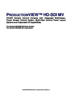
Overview The M8705A tape drive represents the fifth-generation of LTO tape drive technology capable of storing up to 3TB per cartridge. The half-height tape drive is designed for NonStop servers and BladeSystems. It supports LTO-5 media and provides investment protection with full read and write backward support with LTO-4 media, and the ability to read LTO-3 media cartridges. By nearly doubling the capacity of previous generation LTO tape drives, fewer data cartridges are required to meet storage needs. Figure 1-1. Front View of Tape Drive 1
2
3
4
5
6
7
8
1. Cartridge Door 2. On/Off Switch 3. Encryption LED 4. Clean LED 5. Tape LED 6. Drive LED 7. Ready LED 8. Eject Button
M8705A Tape Drive Installation and User’s Guide —694638-001 1 -1
Features
Overview and Features
Features High-Capacity: Large-capacity tape drive capable of storing up to 3TB of compressed storage on a single cartridge, requiring fewer data cartridges to meet storage needs, significantly reducing IT costs Secure: Support for WORM media provide a secure method for long-term retention of critical data records Fast: Fast data transfer rate to meet demands of even the tightest backup window Reliable:
! ! ! ! !
Data rate matching feature automatically adjusts the drive's read and write speed based on the server environment, which increases performance, reduces mechanical wear on the drive, and extends tape life Softload feature automatically takes the data cartridge and moves it into the load position Advanced tape leader capture design ensures fail-safe cartridge loading Active head cleaning provides automated cleaning that increases head life and reduces the need for using the cleaning cartridge Lower power consumption for maximum reliability with minimum environmental costs
M8705A Tape Drive Installation and User’s Guide —694638-001 1 -2
2
Installing and Configuring the Tape Drive for the NonStop NSSeries Integrity Server This section includes: Installation
2-1
Configuration
2-2
Installation 1. Unpack and check the shipment. Figure 2-1. Front View of Tape Drive
2. Connect one end of the SAS cable to the SAS port at the rear of the tape drive. 3. Connect the opposite end of the SAS cable to one of the SAS HBA connections on the rear of the CLuster I/O Module (CLIM). For more information on the CLuster I/O Module see the “CLuster I/O Module (CLIM) Installation and Configuration Guide.” You can use any of the SAS cables in Table 2-1.
M8705A Tape Drive Installation and User’s Guide —694638-001 2 -1
Installing and Configuring the Tape Drive for the NonStop NS-Series Integrity Server
Configuration
Table 2-1. SAS Cables Part Number
Description
AE466A
2M External Infiniband (SFF-8470) to Mini SAS (SFF-8088) 1 x SAS Cable
AE468A
4M External Infiniband (SFF-8470) to Mini SAS (SFF-8088) 1 x SAS Cable
4. Connect the CLuster I/O Module to a NonStop NS-series server. 5. Connect one end of the power cord to the unit’s AC power receptacle and connect the other end to an AC power outlet. 6. Power on the tape drive.
Configuration 1. Issue an SCF ADD TAPE command. This is an example: -> ADD TAPE $M8705A, SENDTO STORAGE, CLIM C1002531, LUN 1 You can specify backup and primary CPUs if you need to balance the processing load to other CPUs. 2. After configuring the tape drive in SCF, issue the following command: SCF> START TAPE $tape Example: SCF> START TAPE $M8705A
For complete details about the ADD and START commands, including command syntax, see the SCF Reference Manual for the Storage Subsystem. For more information on connecting tape drives to the CLIM, see the NonStop CLuster I/O Module (CLIM) Installation and Configuration Guide.
M8705A Tape Drive Installation and User’s Guide —694638-001 2 -2
3
Configuring the Tape Drive for the NonStop BladeSystem Server This section covers: Configuration Overview
3-1
Adding the Tape Drive
3-1
Start the Tape Drive
3-2
Verify the Tape Configuration
3-2
Troubleshoot the Tape Configuration
3-3
Configuration Overview NonStop BladeSystems can connect to the tape drive by means of a CLIM (CLuster I/O Module). Each CLIM provides access to the tape drive through a SAS connection. For more information on connecting tape drives to the CLIM, see the NonStop CLuster I/O Module (CLIM) Installation and Configuration Guide. For a list of tape drives supported for use with Blades-series servers, see the NonStop BladeSystem Installation Manual.
Adding the Tape Drive Issue an SCF ADD TAPE command to configure the tape drive. This is an example: -> ADD TAPE $M8705A, SENDTO STORAGE, CLIM C1002531, LUN 1 You can specify backup and primary CPUs if you need to balance the processing load to other CPUs.
M8705A Tape Drive Installation and User’s Guide —694638-001 3 -1
Configuring the Tape Drive for the NonStop BladeSystem Server
Start the Tape Drive
Start the Tape Drive After the tape drive is added, use the START command to start it:
-> START TAPE $M8705A
Verify the Tape Configuration To check that the tape drive was successfully added, issue the SCF STATUS tapename, detail command:
->STATUS TAPE $M8705A, DETAIL STORAGE - DETAILED STATUS TAPE \OSMQA5.$M8705A Tape Process Information: LDev
State
Primary PID
Backup PID
DeviceStatus
197
STARTED
0,322
1,351
ONLINE, BOT
Tape I/O Process Information: Library File....... Program File....... $SYSTEM.SYS00.OTPPROCP Current Settings: ACL................ NOT INSTALLED
Buffer Level...... RECORD
Checksum Mode...... NORMAL I/O
*Compression....... ON
*Density............ 38000
Media Type........ Not applicable
Opens.............. 0
*RecSize........... 2048
Short Write Mode... ALLOWED, PADDED
SubType........... 18
Volume Switching... TRANSPARENT
M8705A Tape Drive Installation and User’s Guide —694638-001 3 -2
Configuring the Tape Drive for the NonStop BladeSystem Server
Troubleshoot the Tape Configuration
Troubleshoot the Tape Configuration ! !
Check that the processes on the CLIM are running and if they are not, start them. If either of these conditions occur:
"
The SCF STATUS CLIM $ZZCIP.* command shows that the CLIM object is still in the STARTING state after a few minutes, or
"
The SCF STATUS TAPE command shows that the tape drive is still in the STARTING state after a few minutes
"
The OSM Service Connection indicates that the resource needs attention
Check for event messages in the Event Message Service (EMS) log. Use the OSM Event Viewer to view the EMS log. Refer to the Operator Messages Manual for cause, effect, and recovery information for event messages.
M8705A Tape Drive Installation and User’s Guide —694638-001 3 -3
Configuring the Tape Drive for the NonStop BladeSystem Server
Troubleshoot the Tape Configuration
M8705A Tape Drive Installation and User’s Guide —694638-001 3 -4
4
Operation
This section includes: Front View of Tape Drive
4-1
Loading a Tape Cartridge
4-2
Unloading a Tape Cartridge
4-3
Removing Power from the Tape Drive
4-3
Using the Correct Media
4-4
Front View of Tape Drive Figure 4-1. Front View of Tape Drive 1
2
3
4
5
6
7
8
1. Cartridge Door 2. On/Off Switch 3. Encryption LED 4. Clean LED 5. Tape LED 6. Drive LED 7. Ready LED 8. Eject Button
M8705A Tape Drive Installation and User’s Guide —694638-001 4 -1
Loading a Tape Cartridge
Operation
Loading a Tape Cartridge 1. Lift the cartridge door and insert the cartridge into the slot in the front of the drive with the white arrow uppermost and facing the drive door. Figure 4-2. Inserting a Tape Cartridge
1
2
3
1. Label Area 2. Arrow Indicates Leading Direction 3. Cartridge Door 2. Apply gentle pressure until the drive takes the cartridge and loads it. 3. The Ready light flashes green while the drive performs its load sequence. When the cartridge is loaded, the Ready light shows steady green.
M8705A Tape Drive Installation and User’s Guide —694638-001 4 -2
Unloading a Tape Cartridge
Operation
Unloading a Tape Cartridge CAUTION: Never try to remove a cartridge before it is fully ejected.
1. Press the Eject button on the front panel. Figure 4-3. Ejecting a Tape Cartridge
1 1.Eject Button 2. The drive will complete its current task, rewind the tape to the beginning, and eject the cartridge. The rewind process may take up to 10 minutes. The Ready light will flash to indicate that the unload is still in progress.
Removing Power from the Tape Drive To ensure reliable operation, do not remove power from the drive during read, write, fast-search, load and unload activities.
M8705A Tape Drive Installation and User’s Guide —694638-001 4 -3
Using the Correct Media
Operation
Using the Correct Media For best performance it is recommend to use HP branded media.
LTO Cartridge Media The following are tips to ensure maximum LTO cartridge media performance and life: 1. Place labels only in the recessed area, just above the write protection switch (See Figure 4-4). Never place labels on the top, bottom sides or rear of the cartridge, they can cause loader faults and interfere with normal operations. Such labels can come off inside the equipment causing damage. 2. Always inspect cartridges for incorrect or improperly attached labels. 3. Never erase information on a cartridge label, always replace the label. Note. Barcode labels may be placed on the media with the alphanumeric characters on the left or the right.
Figure 4-4. Barcode Label Installation (LTO)
M8705A Tape Drive Installation and User’s Guide —694638-001 4 -4
LTO Cartridge Media
Operation
Cleaning Cartridges The recommended cleaning cartridges is the HP Ultrium universal cleaning cartridge, C7978A (Orange). This cleaning cartridge is designed to work with any Ultrium drive. It may be used for up to 50 cleans. Note. The earlier HP Ultrium Cleaning cartridge, C7979A (Blue), is supported on LTO-2 and LTO-3 tape drives (but not on LTO-4 and LTO-5 tape drives). Do not use early, non-universal LTO cleaning cartridges from other manufacturers.
Cleaning the Tape Drive The tape drive does not require regular cleaning. An Ultrium universal cleaning cartridge should only be used when the orange Clean LED is flashing. You must use the Ultrium Universal Cleaning cartridge with the tape drive, as other cleaning cartridges will not load and run. To clean the tape drive: 1. Insert the Ultrium Universal Cleaning cartridge. 2. The drive will carry out its cleaning cycle and eject the cartridge on completion (which can take up to 5 minutes). During the cleaning cycle the orange Clean LED will be on solidly and the green Ready LED will flash. Each HP Ultrium universal cleaning cartridge cleaning cartridge (C7978A) can be used up to 50 times with Ultrium tape drives. If the cleaning cartridge is ejected immediately with the Tape LED on, it has expired.
Data Cartridges LTO tape drives use LTO tape cartridges. These are single-reel cartridges that match your drive's format and are optimized for high capacity, throughput and reliability. Compatible media can be recognized by the Ultrium logo, which is the same as the logo on the front of your drive. Do not use other format cartridges in your tape drive and do not use LTO cartridges in other format tape drives. For optimum performance always use a data cartridge that matches the specification of your tape drive, (see table below). A lower specification will have a lower transfer speed and may not support write activities; a higher specification will not support read or write.
M8705A Tape Drive Installation and User’s Guide —694638-001 4 -5
LTO Cartridge Media
Operation
Table 4-1. LTO5 Media Compatibility LTO-2 (N152xA)
LTO-3 (M850x / N152xA)
LTO-4 (M860xA)
LTO-5 (M870xA)
Ultrium1 RW Media
Read/Write
Read Only
Not Supported
Not Supported
Ultrium2 RW Media
Read/Write
Read/Write
Read Only
Not Supported
Ultrium3 RW & WORM Media
N/A
Read/Write
Read/Write
Read Only
Ultrium4 RW & WORM Media
N/A
N/A
Read/Write
Read/Write
Ultrium5 RW & WORM Media
N/A
N/A
N/A
Read/Write
Media/Drive
Note. This table shows the importance of a sequential progression for LTO drives. Customers need time to upgrade their media, skipping a generation creates media management issues.
M8705A Tape Drive Installation and User’s Guide —694638-001 4 -6
LTO Cartridge Media
Operation
Write Protecting Cartridges WARNING: Always remove the cartridge from the tape drive before you change the write protection.
If you want to protect the data on a cartridge from being altered or overwritten, you can write protect the cartridge.
! !
To write protect a cartridge, push the switch to the right to prevent any data recording on the cartridge. Note the padlock on the tab that indicates that the cartridge is protected. To write enable a cartridge, push the switch to the left to allow data recording on the cartridge.
Figure 4-5. Write Protecting a Tape Cartridge
1
1. Write Protect Tab CAUTION: Write protection will not protect your cartridges against magnets. Write-protection will not prevent a cartridge being erased by bulk-erasure or degaussing. Do not bulk erase Ultrium format cartridges. This will destroy pre-recorded servo information and make the cartridge unusable. M8705A Tape Drive Installation and User’s Guide —694638-001 4 -7
LTO Cartridge Media
Operation
Handling Cartridges 1. Do not open the cartridge door and touch the tape media. 2. Do not attempt to clean the tape path or tape guides inside the cartridge. 3. Do not leave cartridges in the drive. The tape loses tension in the power-off state, which can lead to problems, particularly if the drive has been moved. 4. Do not leave cartridges in excessively dry or humid conditions. 5. Do not leave cartridges in direct sunlight or in places where magnetic fields are present (for example, under telephones, next to monitors or near transformers). 6. Do not drop cartridges or handle them roughly. 7. Stick labels onto the label area only. 8. Do not bulk erase (or degauss) Ultrium format cartridges because this will render them unusable.
Labeling Tape Cartridges The ACL contains a bar code reader that reads the tape labels and stores the inventory data in memory. The ACL then provides the inventory information to the server, OCP, and RMI. Having a bar code label on each tape cartridge enables the bar code reader to identify the cartridge quickly, thereby speeding up inventory time. Make it a practice to use bar code labels on your tape cartridges.
Tip. The bar code scanner must scan each tape or the back of the storage slot until it reads the bar code label for the cartridge or storage slot, or determines that the slot is empty. The bar code scanner can identify a properly labeled cartridge on the first scan. It can identify an empty slot on the second scan. It will try several more scans and then tap on the cartridge before determining that an unlabeled cartridge is in the slot, which takes about four times as long as identifying a properly labeled cartridge. Even if you do not need the bar code information, use bar code labels to speed up inventory time.
M8705A Tape Drive Installation and User’s Guide —694638-001 4 -8
LTO Cartridge Media
Operation
Ultrium tape cartridges have a recessed area located on the face of the cartridge next to the write-protect switch. Use this area for attaching the adhesive-backed bar code label. Only apply labels as shown: Figure 4-6. Tape Labeling
IMPORTANT: The bar code label should only be applied as shown, with the alphanumeric portion facing the hub side of the tape cartridge. Never apply multiple labels onto a cartridge because extra labels can cause the cartridge to jam in a tape drive.
Operating and Storage Environment To prevent condensation and for long life, the cartridge should only be operated or stored as follows:
! ! ! !
Operation: 10° C to 45° C (50° F to 113° F) Day-to-day storage (in plastic container): 16° C to 32° C (60° F to 90° F) Non-condensing relative humidity: 10% to 80% (operating), 20% to 60% (nonoperating) Wet bulb temperature should not exceed 26° C (79° F)
Tapes intended for long-term storage should be stored in the plastic containers, at temperatures between 5° C and 23° C (41° F and 73° F) and 20% to 60% relative humidity.
M8705A Tape Drive Installation and User’s Guide —694638-001 4 -9
LTO Cartridge Media
Operation
M8705A Tape Drive Installation and User’s Guide —694638-001 4- 10
5
Troubleshooting
This section includes: Problems With Tape Cartridges
5-1
Understanding LED Sequences
5-2
Encryption LED
5-7
Problems With Tape Cartridges If you experience any problems using HP branded tape cartridges, check:
! ! !
The cartridge case is intact and that it contains no splits, cracks or damage. The cartridge has been stored at the correct temperature and humidity. This prevents condensation. See the insert included with the tape cartridge for storage conditions. The write-protect switch is fully operational. It should move from side to side with a positive click.
The Tape Cartridge is Jammed 1. Press the Eject button on the front of the tape drive. 2. Power down the drive. 3. Disconnect the data cable. 4. After at least 15 seconds, power the tape drive back up and wait till the tape drive is idle/ready. Caution: Use care when disconnecting data cables to ensure that connectors are not reversed, pins are not bent, and so on. IMPORTANT: Powering up with a tape cartridge in the tape drive can take several minutes. It is important that you allow sufficient time for the tape drive to complete rewinding the tape cartridge. If you interrupt it, you may damage the media or the tape drive.
5. Ensure that drive activity has stopped (waiting 10 minutes after power up is a good rule of thumb). Push the Eject button. This step attempts to overcome unload issues due to the tape drive being in an abnormal state or because Prevent Media Removal has been incorrectly left on after being set by a rogue application.
M8705A Tape Drive Installation and User’s Guide —694638-001 5 -1
Understanding LED Sequences
Troubleshooting
6. Initiate a force eject or emergency unload operation by pressing and holding the Eject button for 15 seconds. This step causes the drive to try everything possible to unload the tape. Caution: You may lose data if you force eject a tape cartridge that is in the middle of a backup. The tape cartridge may also become unreadable because an EOD (End of Data) mark may not be properly written.
7. If the cartridge is still jammed, the tape drive has failed. Contact support.
Understanding LED Sequences Figure 5-1. Front View of Tape Drive 1
2
3
4
5
6
7
8
1. Cartridge Door 2. On/Off Switch 3. Encryption LED 4. Clean LED 5. Tape LED 6. Drive LED 7. Ready LED 8. Eject Button
M8705A Tape Drive Installation and User’s Guide —694638-001 5 -2
Understanding LED Sequences
Troubleshooting
The LED sequences in the following table relate to the Clean, Tape, Drive and Ready LEDs: Table 5-1. Clean, Tape, Drive and Ready LED Sequences LED Sequence
All LEDs OFF
Cause
Action Required
Drive may not have power, may be faulty or may have been power cycled or reset during a firmware upgrade.
Make sure the drive is switched on. The power on/off switch on an external drive incorporates a green LED. Check the power cord connection and replace the cable if necessary. On external drives, you can use the power cord from your monitor or another device to check that the connection is working. If the power supply is present and all LEDs remain off, power cycle or reset the drive. If it still fails, call for service.
The drive has failed to execute power-on self test (POST).
Power cycle or reset the drive. If the error condition reappears, call for service.
The drive is ready for operation
None. This is normal.
The drive is carrying out a normal activity (read, write).
None.
Ready and Clean OFF. Drive and Tape FLASH
Ready is ON
Ready FLASHES
If the drive is upgrading firmware, do not reset or power cycle it.
M8705A Tape Drive Installation and User’s Guide —694638-001 5 -3
Understanding LED Sequences
Troubleshooting
Table 5-1. Clean, Tape, Drive and Ready LED Sequences LED Sequence
Cause
Action Required
The drive is in OBDR mode.
See “Running HP OBDR.”
The drive is downloading firmware.
None. Do not reset or power cycle the drive.
Firmware is being reprogrammed.
None. Do not reset or power cycle the drive.
The drive requires cleaning.
Load the Ultrium cleaning cartridge. See Cleaning Cartridges on page 4-5 for supported cartridges and instructions.
Ready FLASHES, steady ON FLASHES.
Ready FLASHES fast
Ready is OFF, others are ON
Clean FLASHES
If the Clean LED is still flashing when you load a new or known good data cartridge after cleaning, call for service. Cleaning is in progress.
Ready FLASHES and Clean is ON.
None. The cleaning cartridge will eject on completion. The cleaning cycle can take up to 5 minutes to complete.
M8705A Tape Drive Installation and User’s Guide —694638-001 5 -4
Understanding LED Sequences
Troubleshooting
Table 5-1. Clean, Tape, Drive and Ready LED Sequences LED Sequence
Cause
Action Required
The drive believes the current tape or the tape just ejected is faulty.
Unload the tape cartridge. Make sure that you are using the correct format cartridge; an Ultrium data cartridge or Ultrium Universal Cleaning Cartridge.
Tape FLASHES
Reload the cartridge. If the Tape LED still flashes or starts flashing during the next backup, load a new or known good cartridge. If the Tape LED is now off, discard the 'suspect' tape cartridge. If it is still on, call for service. The tape cartridge memory (CM) may be faulty.
The tape is ejected immediately and Tape FLASHES, or Drive FLASHES on unloading tape.
Write protect the cartridge by sliding the switch on the tape cartridge, see Write Protecting Cartridges on page 4-7 The tape can be loaded and the data read. Once the data is recovered, the cartridge must be discarded.
M8705A Tape Drive Installation and User’s Guide —694638-001 5 -5
Understanding LED Sequences
Troubleshooting
Table 5-1. Clean, Tape, Drive and Ready LED Sequences LED Sequence
Cause
Action Required
The drive mechanism has detected an error.
Load a new cartridge. If the error persists, power cycle or reset the drive. If the Drive LED remains on, call for service.
Drive FLASHES
There is a firmware download problem.
Insert a cartridge to clear the LED sequence. If the condition persists, call for service.
The drive has a firmware error.
Power cycle or reset the drive. Upgrade the firmware. If the condition persists, call for service.
Drive, Tape and Ready FLASH
Drive and Ready ON with Tape and Clean OFF. Alternates repeatedly.
M8705A Tape Drive Installation and User’s Guide —694638-001 5 -6
Encryption LED
Troubleshooting
Encryption LED The encryption LED may be blue or amber, as described in the following table. The state of the other LEDs depends upon the activity, as described below. Table 5-2. Encryption LED Encryption LED (Blue or Amber)
State
On
At power on
Off
The drive is idle and there is no encryption key.
Off with Ready flashing green
The tape drive is reading/writing unencrypted data from another host or unloading a cartridge.
On (solid blue)
The drive is idle but the encryption key is loaded. The drive is ready to read/write encrypted data.
On (solid blue) with Ready flashing green
The drive is reading/writing encrypted data.
Alternate flashing, blue and amber
There is an encryption related error. This is cleared after unload executes or successful encryption/decryption resumes.
M8705A Tape Drive Installation and User’s Guide —694638-001 5 -7
Encryption LED
Troubleshooting
M8705A Tape Drive Installation and User’s Guide —694638-001 5 -8
6
Technical Specifications
This section includes: Physical Specifications
6-1
Specifications
6-1
Environmental Specifications
6-2
SAS Cables
6-2
LTO-5 Media Compatibility
6-3
HP LTO Media Part Numbers
6-4
Physical Specifications Table 6-1. Physical Specifications Characteristics
Product Alone
Height
7.6 cm (3 inches)
Width
22.9 cm (9 inches)
Length
30.5 cm (12 inches)
Weight
3.6 kg (8 pounds)
Specifications Table 6-2. LTO-5 Specifications Characteristic
Specification
Tape Drive
LTO-5, SAS
Maximum Storage Capacity
3 TB compressed per cartridge
Native Data Transfer Rate
140 MB/s
Buffer Size
256 MB
Rewind Tape Speed
9 m/s
MTBF
250,000 hours @100% duty cycle
M8705A Tape Drive Installation and User’s Guide —694638-001 6 -1
Environmental Specifications
Technical Specifications
Environmental Specifications Table 6-3. Environmental Specifications Temperature Range
Operating: 50° F to 95° F (10° C to 35° C) if 6 CFM airflow is provided 50° F to 104° F (10° C to 40° C) if 8CFM airflow is provided for FullHeight, 5CFM airflow for Half-Height
Non-Condensing Humidity Range
Operating: 20 to 80% RH (Non-condensing, max wet bulb temperature = 26C) Non-Operating: 10 to 95% RH (Non-condensing, max wet bulb temperature = 26C)
SAS Cables Table 6-4. SAS Cables Part Number
Description
AE466A
2M External Infiniband (SFF-8470) to Mini SAS (SFF-8088) 1 x SAS Cable
AE468A
4M External Infiniband (SFF-8470) to Mini SAS (SFF-8088) 1 x SAS Cable
M8705A Tape Drive Installation and User’s Guide —694638-001 6 -2
LTO-5 Media Compatibility
Technical Specifications
LTO-5 Media Compatibility Table 6-5. LTO5 Media Compatibility LTO-2 (N152xA)
LTO-3 (M850x / N152xA)
LTO-4 (M860xA)
LTO-5 (M870xA)
Ultrium1 RW Media
Read/Write
Read Only
Not Supported
Not Supported
Ultrium2 RW Media
Read/Write
Read/Write
Read Only
Not Supported
Ultrium3 RW & WORM Media
N/A
Read/Write
Read/Write
Read Only
Ultrium4 RW & WORM Media
N/A
N/A
Read/Write
Read/Write
Ultrium5 RW & WORM Media
N/A
N/A
N/A
Read/Write
Media/Drive
Note. This table shows the importance of a sequential progression for LTO drives. Customers need time to upgrade their media, skipping a generation creates media management issues.
M8705A Tape Drive Installation and User’s Guide —694638-001 6 -3
Technical Specifications
HP LTO Media Part Numbers
HP LTO Media Part Numbers Table 6-6. HP LTO Media Part Numbers Description
Part #
HP LTO-5 Ultrium 3TB RW Data Cartridge
C7975A
HP LTO-5 Ultrium 3TB RW Custom Labeled Data Cartridge 20 Pack
C7975AL
HP LTO-5 Ultrium 3TB WORM Data Cartridge
C7975W
HP LTO-5 Ultrium Non-custom Labeled Data Cartridge 20 Pack
C7975AN
HP LTO-5 WORM Custom Labeled Cartridge 20 Pack
C7975WL
HP LTO-5 RW Custom Labeled No Case Data Cartridge 20 Pack
C7975AC
HP LTO-5 Ultrium 3.0 TB RFID Custom Labeled Data Cartridge (20 pack)
C7975AF
HP LTO-5 Ultrium 3.0 TB RFID Non Custom Labeled Data Cartridge (20 pack)
C7975AJ
HP LTO-5 Ultrium 3.0 TB RFID Eco Pack (No Case) Data Cartridge (20 pack)
C7975AK
HP LTO-4 Ultrium 1.6 TB RW Data Cartridge
C7974A
HP LTO-4 Ultrium 1.6TB RW Custom Labeled Data Cartridge (20 pack)
C7974AL
HP LTO-4 Ultrium 1.6 TB WORM Data Cartridge
C7974W
HP LTO-4 Ultrium 1.6TB Non Custom Labeled Data Cartridge (20 pack)
C7974AN
HP LTO-4 Ultrium 1.6 TB WORM Custom Labeled Data Cartridge (20 pack)
C7974WL
HP LTO-4 Ultrium 1.6 TB RFID Custom Labeled Data Cartridge (20 pack)
C7974AF
HP LTO-4 Ultrium 1.6 TB RFID Non Custom Labeled Data Cartridge (20 pack)
C7974AJ
HP LTO-4 Ultrium 1.6 TB RFID Eco Pack (No Case) Data Cartridge (20 pack)
C7974AK
HP LTO-3 Ultrium 800 GB RW Data Cartridge
C7973A
HP LTO-3 Ultrium 800 GB RW Custom Labeled Data Cartridge (20 pack)
C7973AL
HP LTO-3 Ultrium 800 GB Non Custom Labeled Data Cartridge (20 pack)
C7973AN
HP LTO-3 Ultrium 800 GB WORM Data Cartridge
C7973W
HP LTO-3 Ultrium 800 GB WORM Custom Labeled Data Cartridge (20 pack)
C7973WL
HP LTO-3 Ultrium 800 GB RFID Custom Labeled Data Cartridge (20 pack)
C7973AF
HP LTO-3 Ultrium 800 GB RFID Non Custom Labeled Data Cartridge (20 pack)
C7973AJ
HP LTO-3 Ultrium 800 GB RFID Eco Pack (No Case) Data Cartridge (20 pack)
C7973AK
HP LTO-3 Ultrium RW Bar Code label pack
Q2007A
HP LTO-3 Ultrium WORM Bar Code label pack
Q2008A
HP LTO-4 Ultrium RW Bar Code label pack
Q2009A
HP LTO-4 Ultrium WORM Bar Code label pack
Q2010A
HP LTO-5 Ultrium RW Bar Code Label Pack
Q2011A
HP LTO-5 Ultrium WORM Bar Code Label Pack
Q2012A
HP LTO Ultrium Universal Cleaning Cartridge
C7978A
M8705A Tape Drive Installation and User’s Guide —694638-001 6 -4
Index A AC power outlet 2-2 AC power receptacle 2-2
SCF ADD TAPE command for NonStop BladeSystems 3-1 SCF ADD TAPE command for NonStop Sseries 2-2
C
T
Configuration 2-2
Tape Drive loading a tape cartridge 4-2 unloading a tape cartridge 4-3 Tape drive 1-1 cleaning 4-5 starting for BladeSystem 3-2 starting for NonStop NS-series 2-2 Technical specifications 6-1 environmental specifications 6-2 LTO media compatibility 6-3 physical specifications 6-1 Troubleshooting 5-1 encryption LED 5-2 problems with tape cartridges 5-1 understanding LED sequences 5-2
F Features 1-2
I Installation 2-1
L LTO cartridge media 4-4 barcode 4-4 cleaning 4-5 compatibility 4-6, 6-3 data cartridge 4-5 data cartridges 4-5 handling 4-8 storage environment 4-9 write protecting 4-7
N NonStop BladeSystem 3-1 NonStop NS-series 2-2
O Operation 4-1 Overview 1-1
S SAS cables 2-1
M8705A Tape Drive Installation and User’s Guide —694638-001 Index -1
T
Index
M8705A Tape Drive Installation and User’s Guide —694638-001 Index -2