Team Fantana
Laptop Riser Design Project
Team Members David Harman Robbie Harris Meghan Rogers Tim Samford Drew VanNess
Table of Contents ABSTRACT ........................................................................................................................................ 2 PROBLEM STATEMENT .................................................................................................................... 3 Design Partition ............................................................................................................................. 4 Design Partition Break Down................................................................................................................ 5
CONCEPTUAL DESIGNS .................................................................................................................... 5 Figure 1. Summary of the main subsystem conceptual ideas for the Laptop Riser ........................ 7
SELECTION ANALYSIS ...................................................................................................................... 7 Table 1: Pariwise Comparison to Decide Important Criteria for the Design ................................... 8 Figure 2: Patent 6496360 ....................................................................................................................... 8 Table 2: Evaluation Matrix of Conceptual Designs............................................................................. 9
ENGINEERING ANALYSIS ............................................................................................................... 10 Cost Analysis ......................................................................................................................................... 10 Ergonomic Analysis.............................................................................................................................. 10 Figure 3: Ergonomic Recommendations for Workspace.................................................................. 11 Finite Element Analysis........................................................................................................................ 11
PART DRAWINGS............................................................................................................................ 12 PROTOTYPE CONSTRUCTION ......................................................................................................... 12 COMPLETED PROTOTYPE PICTURES .............................................................................................. 13 Figure 4. Completed isometric view in expanded position............................................................... 13 Figure 5. Expanded position side view............................................................................................... 14 Figure 6. Close up of expanded isometric view................................................................................. 14
MODIFICATIONS ON PROTOTYPE FROM DESIGN MODEL .............................................................. 14 Figure 7. Comparison of the design model on the left and the prototype on the right.................. 16
IMPROVEMENTS ............................................................................................................................. 16 REFERENCES:................................................................................................................................ 17 Appendix A: FEM Analysis......................................................................................................... 18 Appendix B: Engineering Drawings ........................................................................................... 26 Appendix C: Bill of Materials...................................................................................................... 29
ABSTRACT The goal of the design project was to create an adjustable lap top desk for portable computers to prevent heat created by the computer battery from reaching the user’s lap. The device was also designed to bring the portable computer to a more comfortable working height, while also having the ability to fold up into a low profile for easy storage. The design was meant to be easy, safe, and comfortable to use. The design had to be able to support at least the weight of a heavy laptop computer plus wrist and hand weight, while also accounting for a safety factor. Such a device would be targeted at those people who own laptop computers that dissipate heat through the bottom surface, as well as individuals who experience discomfort in their back when using their computer. The design is also an attractive accessory because of its ability to store easily inside most laptop computer carrying cases. Numerous design proposals were evaluated using a pairwise comparison, in which stability of the system on the lap and between the device and computer were deemed the most important design considerations. To address these issues, the device was designed with a strong aluminum scissor arm elevation mechanism, an injection molded plastic tray with gripping rubber top, and a lap interface made of a lightly elastic fabric. An ergonomic study was performed to determine the optimal dimensions of the lap interface in order to provide the highest level of comfort. The created prototype differed somewhat from the designed device, but provides adequate proof of concept. The tray was made from PVC connected with aluminum brackets for robustness, and the lap interface was made from a shirt fabric that was somewhat more elastic than desired. However, the prototype is fully functional and can only be improved upon by the proposed design differences. The design proved successful in addressing the functions deemed necessary for a useful product. As an added bonus, the design also proved to be relatively inexpensive when compared to similar products that did not offer the same level of adjustability and convenience.
2
PROBLEM STATEMENT Team Fantana has selected to design and create the Laptop Riser for its Capstone Design project. Laptop computers (“laptops”) consume electricity and produce heat as a byproduct. When used on the lap, these computers often produce enough heat to make the user uncomfortable. The purpose of the Laptop Riser (“device”) is to make the use of any laptop computer more comfortable for the user by providing space between the laptop and the user’s legs. With few products on the market that address laptop heat, the Laptop Riser is a new approach to an issue that is largely ignored. While the final design of the device is not yet completed, the functions it will serve necessitate certain components. The first component is the lap interface. This is the part of the device that will actually come into contact with the user. Next, a support structure based at the lap interface will be required to lift the laptop off of the users lap. Finally, the laptop holder will be at the top of the support structure and will come into contact with the laptop. Different designs for the device may also include varying springs and actuating devices to serve further functions such as platform stability, actuation from storage mode to in-use mode, adjustment to the laptop’s size, and others. To be a viable product, the device will need to meet the needs of most laptop users who use their laptops on their laps. The scope of this project, therefore, will cover all standard, commercially available laptops. To meet this requirement, the device will need to provide a secure platform for use that is adjustable to fit any laptop. Furthermore, the device will also need to fit most people. For this reason, an adjustable lap interface will be required. Along with providing a stable, adjustable way to reduce the heat felt by the user, the device also has the design goal of being easily storable. This requirement means that the device must fit flat along the bottom of the laptop when not in use and be small enough for storage while attached to the laptop in the laptop’s carrying case. This ease of storage sets the Laptop Riser apart from the few other products that address laptop heat. The success of the Laptop Riser will depend not only on its novelty, but also on its practicality. Therefore, certain weight and strength requirements are apparent. Since most portable laptops weigh between 3.5 and 8 pounds, the device must be able to support this weight. In addition to the laptop weight, it is foreseeable that some users will rest their forearms on the laptop. This weight must also be supported by the device. To minimize the negative
3
impact on the user while using and transporting the laptop, the device must weigh no more than some acceptable fraction of the laptop’s weight. This fraction must be small enough that the additional weight is almost unnoticeable. The effect of both of these requirements is that the device must be able to support 8 pounds plus the user’s applied weight while itself only weighing some fraction of 3.5 pounds. This combination of constraints along with the adjustability of the device makes the Laptop Riser suitable for use with almost any laptop regardless of size. Upon completion of the design of the Laptop Riser, it will be evaluated according to the design goals and constraints listed above. More specifically, the device will be judged based on the thickness it adds to a laptop when stored together, its weight, the weight it can support, the increased comfort it provides the user, its ability to adjust to laptops of different sizes, as well as its ease of use. With these criteria successfully met, the Laptop Riser should enjoy success in the market. The market itself supports the idea of the Laptop Riser. Over 100 million people around the world use laptops, and in the United States, laptop sales regularly rival or surpass sales of desktop computers. The unavoidable heat that all of these laptops subject their users to makes the market for the Laptop Riser potentially as large as the market for laptops. With no leader in the products that address laptop heat and even fewer that have all of the design goals mentioned above, the Laptop Riser is positioned to become the consensus must-have laptop accessory in a market of millions. Design Partition Using the problem statement as a guide, the laptop riser was divided into subsystems with design goals for each. Although the final design did not incorporate the exact subsystems below, the design partition did reflect the original design thought process and ultimate goals of the design. The design partition was broken up into four fairly obvious systems. The goals of each system were geared towards ease of use and a comfortable fit for most people. Since this device’s main purpose was to provide better comfort while using a laptop, there could not be anything uncomfortable or inconvenient about the product. The design partition is listed below.
4
Design Partition Break Down Laptop Interface – The surface on which the laptop is held must support the laptop and have enough friction to prevent the laptop from slipping. Actuating Mechanism- User friendly mechanism to easily open the device. Support – Design must be able to support the laptop in the “up” position. Lap Interface – The bottom of the device which rests on the user’s lap must be able to fit a wide range of users. CONCEPTUAL DESIGNS Several conceptual designs were considered for the Laptop Riser.
The device was
divided into four subsystems, and the conceptual designs were amalgamations of the variations of these subsystems. The four subsystems were the laptop interface, the actuating mechanism, the support system, and the lap interface. A brief description of each of the main proposals for each of the subsystems is given below. A figure is given at the end of this section summarizing all of the main subsystem conceptual designs. Three ideas were considered for the laptop interface. The first and simplest idea was a rubber sheet attached to the top of the Laptop Riser. The rubber would increase the coefficient of friction between the laptop and the device to prevent slipping. The second idea was raised lips on the side of the device. These lips would act as a short wall, preventing the laptop from sliding off the side of the device. The third idea was a swing arm that would swing over the top of uncritical portions of the laptop to provide a type of clamping action. The final idea was a strap to go around the top of the laptop. After reviewing these ideas, the rubber sheet and lips were chosen for the final design. This decision was based on the ease of manufacture, ease of use, and the sufficient prevention of movement expected from this combination of ideas. The actuating mechanism is the machinery that opens the device. All of the ideas involved either a spring-loaded button or a manual opening process instead of an integrated mechanism. After reviewing the lack of utility of springs in the design beyond actuation, a manual opening process was chosen. In the final design, the device is actuated by lifting the top section and locking the sliders into place on the side bars. The support system was conceived in several ways as it is the main focus of the design problem. The first system was two pairs of swing arms on either side of the device. These
5
swing arms laid horizontally while not in use and rotated up to vertical to act as columns at each corner to support the top section of the device. The second system was a similar to the first system. Instead of one swing arm at each corner, there were two that raised up together in a scissoring action to support the top section. The third system was a telescoping set of plastic hoops that were supported inside by compression springs. The fourth system involved legs resembling barn doors that would open down from the bottom of the laptop. These legs would act as columns on either side of the device. The final design included a variation of the scissor arm system with one large set of scissor arms on either side of the device instead of two. With a system of notches and sliders, this approach provided the most stable support system without the threat of arms falling down, the annoyance of springs bouncing the laptop, or the complexity of unfolding barn-door-type legs from the bottom of the device. The final subsystem is the lap interface. The main proposals for this subsystem included bars with and without a foam covering, a mesh base, and a foam base. After deciding that the bars would be too uncomfortable and would add to the complexity of use and that the foam base may be too hot and would compromise storage goals, the mesh base was chosen for the final design. The mesh base has the added feature of being able to absorb some jarring that may occur in automobiles or other similar environments. proposals mentioned above.
6
Figure 1 below summarized the subsystem
Swing arm support system Spring-loaded actuation Swing arm laptop interface
Telescoping support system Bar lap interface Rubber laptop interface (not visible)
Scissor arm support system Strap laptop interface Spring actuating mechanism
Barn door support system Mesh lap interface Lip laptop interface
Figure 1. Summary of the main subsystem conceptual ideas for the Laptop Riser
SELECTION ANALYSIS In order to determine which of the five original concepts was the best, a selection analysis was completed.
The first step included the creation of a pairwise comparison matrix to
determine which criteria were most important to the design. The results of this matrix are shown in Table 1. Fifteen different criteria, including a baseline criterion that the device shall be made to kill a person, were judged against each other with a 0/1 ranking system where a 1 means that parameter is more important than the other.
The score for each column was totaled and the
overall scores were normalized to reveal the most important criteria: the stability of the system on the user’s lap and that the produce does not interfere with the laptop operation.
7
Height for typing
Height for heat dissipation
Comfortable lap interface
Lightweight
Ease of manufacturing
Ease of operation
Stability of laptop interface
Dampening
Stability of system on lap
Maintenance
Aesthetics
Interference with laptop operation
No necessary setup
Will kill a person
X 0 1 0 0 0 0 1 0 1 0 0 1 0 0
1 X 1 1 1 1 1 1 0 1 1 1 1 0 0
0 0 X 0 0 0 0 1 0 1 0 0 1 0 0
1 0 1 X 0 0 0 1 0 1 0 0 1 0 0
1 0 1 1 X 0 0 1 0 1 0 0 1 0 0
1 0 1 1 1 X 1 1 0 1 1 1 1 1 0
1 0 1 1 1 0 X 1 0 1 0 0 1 0 0
0 0 0 0 0 0 0 X 0 1 0 0 1 0 0
1 1 1 1 1 1 1 1 X 1 1 1 1 1 0
0 0 0 0 0 0 0 0 0 X 0 0 0 0 0
1 0 1 1 1 0 1 1 0 1 X 0 1 0 0
1 0 1 1 1 0 1 1 0 1 1 X 1 0 0
0 0 0 0 0 0 0 0 0 1 0 0 X 0 0
1 1 1 1 1 0 1 1 0 1 1 1 1 X 0
1 1 1 1 1 1 1 1 1 1 1 1 1 1 X
SCORE
Storage Storage Height for typing Height for heat dissipation Comfortable lap interface Lightweight Ease of manufacturing Ease of operation Stability of laptop interface Dampening Stability of system on lap Maintenance Aesthetics Interference with laptop operation No necessary setup Will kill a person
Normalized Score
Table 1: Pariwise Comparison to Decide Important Criteria for the Design Pairwise Comparison Matrix
10 3 11 9 8 3 7 12 1 14 6 5 13 3 0
0.71 0.21 0.79 0.64 0.57 0.21 0.50 0.86 0.07 1.00 0.43 0.36 0.93 0.21 0.00
The next step in the selection analysis was to take the different subsystems from the design concepts and see how well they fit the each criterion. In order to have a baseline off of which to judge, an existing product, shown in Figure 2, was also judged against our criteria.
Figure 2: Patent 6496360
8
Table 2 presents the results from this analysis. Each subsystem was judged on a scale from 0 to 4 with a score of 4 meaning it fits the criteria perfectly and a score of zero meaning it
Mesh Suspension Strap
Folding and telescoping supports
Velcro strips
N/A
N/A
4 N/A
N/A
3
2
3
Patent 6496360
N/A N/A N/A N/A N/A N/A N/A N/A
4
Flat plastic surface
4
N/A N/A N/A N/A
Front edge lip
4
4 N/A
Latching swing arms
4
N/A
Elastic Strap
4
N/A
Rubber pad
4
N/A N/A N/A N/A
Laptop Computer Interfaces
2
Barn Doors
Plain bars
4
Telescoping
Flat surface
2
Swing Arms
Foam bars
2
Scissor arms
Memory foam
4
Support Systems
Mesh suspension straps
Lap Interfaces
Weighted value
doesn’t fit at all.
Storage
0.71
4
3
4
4
Height for typing
0.21
N/A N/A N/A N/A N/A
4
4
4
4
Height for heat dissipation
0.79
N/A N/A N/A N/A N/A
4
4
4
Comfortable lap interface
0.64
4
4
2
1
1
Lightweight
0.57
4
2
2
3
2
3
3
1
2
3
3
2
3
4
4
2
Ease of manufacturing
0.21
4
1
2
4
3
1
2
3
4
4
3
1
4
4
4
4
3
Ease of operation
0.50
3
4
3
4
4
3
3
3
2
4
3
3
4
4
3
2
3
3
3
4
N/A N/A
4
Stability of laptop interface
0.86
Dampening
0.07
2
2
1
0
0
Stability of system on lap
1.00
3
4
3
2
2
4
2
3
4
Maintenance
0.43
3
2
2
4
3
2
3
4
4
4
3
3
4
Aesthetics
0.36
4
3
2
4
1
3
2
3
2
4
3
2
Interference with laptop operation
0.93
No necessary setup
0.21
Sum of weighted scores:
N/A N/A N/A N/A N/A
N/A N/A N/A N/A N/A 4
4
3
4
N/A N/A N/A N/A N/A N/A N/A N/A
N/A N/A N/A N/A
4
16.8 14.3 11.1 14.1 10.4
3
3
3
2
16.9 14.4 16.0 16.7
4 N/A N/A
3
1
N/A N/A N/A N/A
N/A
N/A N/A N/A N/A
N/A
3
4 N/A
4
3
4
2
4
3
4
2
2
N/A N/A N/A N/A
N/A
4
3
2
4
4
14.0 11.6 10.1 13.3
12.5
2 N/A N/A
N/A N/A N/A 4
2
Once all the conceptual subsystems and the existing product were judged, their scores were weighted according to the importance of the criteria, and the weighted scores were summed to give a total score for each subsystem design. A final design for the product was created using the highest scored component from each subsystem. For the lap interface, the mesh suspension straps were chosen. For the support system, the scissor arm design proved to fit the criteria the best. Finally, for the laptop computer interface, a rubber pad gave the best score. Also, it should be noted that the scores of each of the chosen subsystem designs are higher than the scores from
9
1
16.8 16.7 12.5
Table 2: Evaluation Matrix of Conceptual Designs
the related subsystems of the already patented product.
4
ENGINEERING ANALYSIS The engineering analysis used for the laptop riser consisted of three different analyses: a cost analysis, an ergonomic analysis, and a FEA analysis on the laptop interface and side bars.
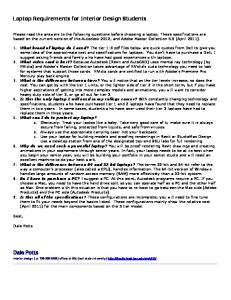
Cost Analysis The cost analysis was computed by taking the cost of the separate parts and adding it together. Overall, the cost to make one laptop riser is approximately $18.59. This cost does not include the cost of fasteners. The actual cost of the laptop riser once in mass production would be much lower than this because it is cheaper to buy the materials in bulk. Ergonomic Analysis An ergonomic analysis was completed and led to many recommendations used to place the final dimensions on the product. The recommended width of the device is 17 inches, taken from the fact that the 95th percentile male has a hip breadth of 16.2 inches (1).
This
recommendation allows the device to fit the majority of laps. In order to provide max comfort and eliminate strain, the tilt angle of the laptop keyboard should be 0° - 15° from horizontal as seen in Figure 1 (2). The height of the surface on which a person is working should be 2 inches below the person’s elbow (3). A 95th percentile male’s elbow rests 3.3 inches above his thigh in the seated position (1). Therefore, in order to obtain a working surface that is 2 inches below his elbow, the laptop riser must be made to reach a maximum height of 1.3 inches.
10
Figure 3: Ergonomic Recommendations for Workspace Finite Element Analysis To analyze the overall design of the plastic and metal parts of the design, finite element analysis was used to examine the stresses, deflection, and overall factors of safety for each part. Since the modeling of the entire system was performed in Solid Edge, the built-in solid modeling module, FEMAP Express, was used to model the system. Two separate parts were modeled, the laptop interface and the supporting scissor arm with the slot down the middle since this obviously would fail before the scissor arm without the middle slot. The laptop interface was modeled using polypropylene as the overall material. Fixed constraints were placed on each of the scissor arm mounting tabs underneath the top and on the slots on each side. These make up the four load bearing points that transfer the load from the top to the scissor arms. A load of 15 pounds was applied to the entire top surface as an evenly distributed load to simulate the weight of a laptop (8 pounds) plus the weight of hands bearing
11
down on the keyboard (7 pounds). The FEM software employed a tetrahedral mesh of 20,103 elements. After running the analysis, the maximum stress was found to be 1.572 ksi with a maximum deflection of 0.3933 inches near the middle of the top. An overall factor of safety of 3.1 was achieved which insured the design would not fail. The scissor arm with the slot down the middle was modeled using 2024 grade aluminum. One fixed constraint was placed on one of the holes at the end of the arm. A load of 15 pounds was applied down the length of the arm on the other hole. This was chosen based on the same design load as the top just to insure that the arm could at a minimum take the same load as the top. The software used a tetrahedral mesh of 10,207 elements to model the part. After the analysis was completed, the maximum stress was calculated to be 2.838 ksi with a maximum deflection of 0.07244 inches at the free end of the arm. This yielded a factor of safety of 14.8 against failure. From this analysis, it was determined that the arm was easily overbuilt, and the type and thickness of material could be decreased safely. The FEM reports and graphics are presented in Appendix A of this report.
PART DRAWINGS Based on the results of the Selection and Engineering Analysis a design was reached. This design included scissor arms with one arm slotted and then other with a hole. A support bar would run in between both arms to add stability and ease of assembly. The mesh base would wrap around square bars on the bottom. The laptop interface is a plate that is covered with a rubber no slip pad. To hold the scissor arms in adjustable places a jagged tooth slot is carved into each of the side bars. A quick design check was done and it was found that there was an additional degree of freedom. This was fixed by adding another jagged tooth assembly to the sides of the laptop plate. The detailed engineering drawings are found in Appendix B. The complete Bill of Materials can be found in Appendix C.
PROTOTYPE CONSTRUCTION The construction of the prototype was done mostly through the Georgia Institute of Technology’s Mechanical Engineering Machine Shop.
After ordering the PVC sheets and
aluminum U-channels from McMaster-Carr, these items were submitted to the machine shop along with design drawings for the Laptop Riser sections. The U-channels were cut to the size
12
appropriate for the side arms of the device and the slots cut out of them. The PVC sheets were cut into four small strips for the scissor arms, four larger strips for the sides of the top section, and one large rectangular piece for the laptop platform. After slots were cut into the appropriate components of the top section, all of the top section components were welded together. The scissor arms were also slotted as necessary. During final assembly of the device with these parts, it was discovered that the warping of the top section from the heat of the welding had caused sufficient misalignment to disallow its use. The misalignment also highlighted the undesirable tendency of the PVC scissor arms to buckle under any uncentered stress. With these two issues, design modifications were made and submitted to the machine shop. Identical scissor arms were made out of the aluminum U-channels. Identical components were also cut from the PVC sheeting for the top section, but were joined together with brackets, nuts, and bolts instead of welding. With these new components, the device was assembled. The mesh lap interface section was sewn into place around the side bars and the rubber sheet attached to the top of the device. The prototype is now complete and functioning. Some modifications that this construction process necessitated and their impacts are outlined in the section titled “Modifications on Prototype from Design Model.”
COMPLETED PROTOTYPE PICTURES
Figure 4. Completed isometric view in expanded position.
13
Figure 5. Expanded position side view.
Figure 6. Close up of expanded isometric view. MODIFICATIONS ON PROTOTYPE FROM DESIGN MODEL In the course of the construction of the prototype, some modifications were needed due to the limited construction resources available. These modifications primarily have an impact on the aesthetics of the device, but some also have an impact on the structural performance of the device in terms weight and stability. In a full scale production setting, the resources lacking thus far would be more practical to obtain and would yield a more polished final product. The major difference between the model and the prototype is a single-piece top section. The prototype features a PVC top fabricated from a flat top, four side pieces, with two small tabs
14
on the under side. These components are all fastened together using bracket-type connectors and nuts and bolts. The design model, however, features all of these components integrated into one plastic top section. This would likely be done using an injection molding process or something similar. The most obvious advantages of the single piece top section are a more aesthetically appealing appearance and fewer opportunities for interference with fewer pieces. A second effect of the prototype fastener system is added weight. Weight is a very important consideration for a carry along laptop accessory such as the Laptop Riser. The prototype fastener system that involves several aluminum brackets, nuts, and bolts is a significant source of added weight which would be conveniently eliminated with a single piece top section. The final effect of the prototype fastener system is added complexity of manufacture. The single piece top section of the design model has the advantage of no threaded fasteners which require increased construction time to turn into place. To reduce the amount of fasteners needed and due to time constraints brought on be necessary prototype modifications, the lips were also eliminated from the prototype. The placement of the prototype’s fastener system, however, serves the same purpose as the fasteners themselves act as small lips. While the prototype achieves its purpose of supporting the load of a laptop, the device as modeled will be more aesthetically appealing, provide fewer opportunities for interference, weigh less, and be easier to manufacture. A second, minor difference between the design model and the prototype are the Uchannels used for the side bars. The design model specifies that the side bars be fabricated from hollow tubes with a rectangular cross-section. The prototype, however, has side bars fabricated from U-channels due to their ease of procurement compared to the tubes.
There is no
foreseeable disadvantage of this modification. Some advantages are apparent, however. The lower amount of material per unit length of the U-channel provides less weight, which was an important design criterion. The open side of the U-channel also allows for easier installation of the bolts used as sliders in its slots. In contrast, the closed cross-section of the tubes would provide a significant installation challenge to insert and hold the nut in place for each bolt as it interfaces with the nut and turned into place. With these considerations, the prototype side bars using U-channels appear to be an improvement over the rectangular cross-section tubes of the design model. The final difference between the design model and the prototype is the cross bar. The cross bar was added after it became apparent during construction that improved lateral stability
15
was needed. As a result the initial design model lacked this feature, but later versions included it. The cross bar that was added is a simple threaded rod that runs through all four scissor legs and holds them in place using nuts. Figure 7 below displays the image of the design model and the prototype beside each other for comparison. The different side bars, the differences in the construction of the top section, the lack of lips and the addition of the cross bar are all apparent in the figure. Note, however, that this version of the design model also includes the cross bar.
Figure 7. Comparison of the design model on the left and the prototype on the right
IMPROVEMENTS Given more time to work on the product, various improvements could have been made to the existing design. Although the product is designed to fit on the laps of the majority of users, a major improvement that could be made to the product is to make it side adjustable. The only adjustability the laptop riser has now it to move it up or down and to tilt it at an angle, giving it an adjustable width would allow for adjustability according to the person’s lap and laptop. Another potential improvement to this design is to include a fold out mouse pad. Not all laptop users use a separate mouse; however, having the option would increase the appeal of the product. One final improvement would be to have a locking mechanism that keeps the device from falling out of its stored position unless actuated. Possible ways of achieving this would be to lock the scissor arms or the stability bar in place while stored.
16
REFERENCES (1) Gordon, C.G., Donelson, S. M, 1988, “1988 Anthropometric Survey of U.S. Army Personnel,” United States Army Natick Research, Development and Engineering Center, Natick, Massachusetts. (2) Van Cott, H.P., Kinkade, R.G., 1972, Human Engineering Guide to Equipment Design, American Institutes for Research. (3) Fraser, T.M., 1989, The Worker at Work, CRC.
17
Appendix A: FEM Analysis FEM of Laptop Riser Top Team Fantana 6/15/07 1. Part Properties Part Name Mass Volume Weight
Top.par 0.000 lbm 0.000 in^3 0.000 lbf
2. Material Properties Material Name Mass Density Young's Modulus Poisson's Ratio Thermal Expansion Coefficient Thermal Conductivity Yield Strength Ultimate Strength
Polypropylene, general purpose 0.033 lbm/in^3 160.000 ksi 0.350 0.0000 /F 1.213 BTU/hr-ft-F 4.800 ksi 0.000 ksi
3. Load and Constraint Information Load Set Load Set Name Load Type Number of Load Elements Load value
Load 1 Force 1 15.000 lbf
18
4. Constraints Number of Constrained Faces
4
5. Study Properties Mesh Type Tetrahedral Mesh Number of elements 20,103 Number of nodes 41,070 Solver Type Nastran
6. Stress Results Type Von Mises Stress
Extent
Value X Y Z 2.590e-003 Minimum 19.000 in 3.768 in 0.000 in ksi 1.572e+000 18.875 in 4.750 in 0.437 in Maximum ksi
19
7. Displacement Results Type
Extent
Value X Y Z 0.000e+000 Minimum 0.000 in 1.365 in 0.437 in Resultant in Displacement 3.933e-001 9.500 in 6.500 in 0.750 in Maximum in
20
8. Factor of Safety Factor of 3.053 Safety Value
Important Information This report should not be used to solely judge a design idea's suitability to a given set of environmental conditions. UGS makes every effort to ensure that its products provide as much guidance and help as possible. However this does not replace good engineering judgment, which is always the responsibility of our users. A qualitative approach to engineering should ensure that the results of this evaluation are evaluated in conjunction with the practical experience of design engineers and analysts, and ultimately experimental test data. The results contained within this report are believed to be reliable but should not be construed as providing any sort of warranty for fitness of purpose.
21
FEM of Side Bar Team Fantana 6/15/07 1. Part Properties Part Name Mass Volume Weight
bar2.par 0.000 lbm 0.000 in^3 0.000 lbf
Material Name Mass Density Young's Modulus Poisson's Ratio Thermal Expansion Coefficient Thermal Conductivity Yield Strength Ultimate Strength
Aluminum, 2024-T4 0.100 lbm/in^3 10600.000 ksi 0.330
2. Material Properties
0.0000 /F 109.202 BTU/hr-ft-F 42.000 ksi 62.000 ksi
3. Load and Constraint Information Load Set Load Set Name Load Type Number of Load Elements Load value
Load 1 Force 1 15.000 lbf
4. Constraints Number of Constrained Faces
1
22
5. Study Properties Mesh Type Tetrahedral Mesh Number of elements 10,207 Number of nodes 21,001 Solver Type Nastran
6. Stress Results Type Von Mises Stress
Extent
Value X Y Z 6.261e-003 Minimum 9.500 in -0.125 in 0.161 in ksi 2.838e+000 0.250 in -0.125 in 0.125 in Maximum ksi
23
7. Displacement Results Type
Extent
Value X Y Z 0.000e+000 Minimum 9.250 in -0.125 in 0.250 in Resultant in Displacement 7.244e-002 0.000 in -0.125 in 0.161 in Maximum in
24
8. Factor of Safety Factor of 14.799 Safety Value
Important Information This report should not be used to solely judge a design idea's suitability to a given set of environmental conditions. UGS makes every effort to ensure that its products provide as much guidance and help as possible. However this does not replace good engineering judgment, which is always the responsibility of our users. A qualitative approach to engineering should ensure that the results of this evaluation are evaluated in conjunction with the practical experience of design engineers and analysts, and ultimately experimental test data. The results contained within this report are believed to be reliable but should not be construed as providing any sort of warranty for fitness of purpose.
25
Appendix B: Engineering Drawings
26
27
28
Appendix C: Bill of Materials
Part Laptop interface Scissor arm – no slot Scissor arm – w/ slot Sidebars Crossbar Specialty fasteners Spacers Mesh Rubber grip
Material Polyprolene Aluminum 2024 1/8” x 1/2” bar Aluminum 2024 1/8” x 1/2” bar Aluminum 2024 ½” x ½” square tube 1/8” steel rod Steel specialty fasteners Nylon 1/8” spacers Specialty elastic mesh Textured rubber pad w/adhesive
29
Quantity 1x 33.5 in^3 2x 9.5 in. 2x 9.5 in. 2x 11 in. 1x 19 in. 8 6 25”x11” 19”x13”