ECE 520 Class Notes
Introduction to ASIC Design Dr. Paul D. Franzon Outline 1. The wonderful world of Silicon 2. Application Specific Integrated Circuits (ASICs) l Typical applications, types, decision making 3. ASIC Design Flow
References 1. Smith, Application Specific Integrated Circuits, Chapter 1. ©2000, Dr. Paul D. Franzon, www.ece.ncsu.edu/erl/faculty/paulf.html
1
ECE 520 Class Notes
The Wonderful World of Silicon About every two years, the number of transistors on a CMOS silicon chip doubles and the clock speed doubles…..This rate of improvement will continue for the next 20 years. Technology Drivers: • Decreasing lithographic feature size, typically measured by the transistor gate length: 0.35 µm ….
0.25 µm ….
0.18 µm 0.15 µm …etc.... 0.050 µm (?)
• Increasing wafer size: 6 inch diameter ….. 8 inch diameter …..etc….. 12 inches (?)
• Increasing number of metal interconnect layers: 4 ….. 6 ….. 8 …… 9 (?)
• Approximately constant cost per wafer to manufacture: About $2,000 - $4,000 per wafer
• Increasing IC yields for ‘large’ (> 1 sq. cm.chips): 60% …. 90% ©2000, Dr. Paul D. Franzon, www.ece.ncsu.edu/erl/faculty/paulf.html
2
ECE 520 Class Notes
From the Semiconductor Roadmap Projections for ‘leading edge’ ICs: (www.sematech.org)
Year
1997
1999
2001
2012
Gate length (nm)
200
140
120
35
Microprocessor total transistors/chip
11M
21M
40M
1.4B
Largest Chip
22 x 22 25 x 32 25 x 34
25 x 52
Microprocessor Clock Speed (MHz)
750
1200
1400
3000
ASIC clock speed (high performance) (MHz)
300
500
600
1500
©2000, Dr. Paul D. Franzon, www.ece.ncsu.edu/erl/faculty/paulf.html
3
ECE 520 Class Notes
ASICs vs. what? Application Specific Integrated Circuit • A chip designed to perform a particular operation as opposed to General Purpose integrated circuits: • An ASIC is NOT software programmable to perform different tasks General Purpose Integrated Circuits: • Programmable microprocessors (e.g. Intel Pentium Series, Motorola HC-11)
l Used in PCs to washing machines • Programmable Digital Signal Processors (e.g. TI TMS 320 Series)
l Used in many multimedia, sensor processing and communications applications • Memory (dRAM, SRAM, etc.) Examples of ASICs: • Video processor to decode MPEG-2 digital TV signals • Audio processor to perform Dolby AC3 encoding • Low power DSP/controller for cell phone ©2000, Dr. Paul D. Franzon, www.ece.ncsu.edu/erl/faculty/paulf.html
4
ECE 520 Class Notes
ASIC Styles 1. Full Custom ASICs
l Every transistor is designed and drawn by hand l Typically only way to design analog portions of ASICs l e.g. part of a custom DES (encryption) processor designed as part of a research project at NCSU:
Gives the highest performance but the longest design time
l Typically only used for analog portions and for very high volume parts (e.g. microprocessors) or for small parts to be used in many different designs 5
©2000, Dr. Paul D. Franzon, www.ece.ncsu.edu/erl/faculty/paulf.html
ECE 520 Class Notes
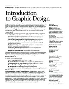
….ASIC Styles 2. Standard-Cell-Based ASICs
l or ‘Cell Based IC’ (CBIC) or ‘semi-custom’ l Standard Cells are custom designed and then inserted into a library
D-flip-flop:
NOR gate:
u These cells are then used in the design by being placed in rows and wired
l l
together using ‘place and route’ CAD tools Some standard cells, such as RAM and ROM cells, and some datapath cells (e.g. a multiplier) are tiled together to create macrocells Custom designed blocks (e.g. microprocessors) might be mixed in as well (sometimes called megacells or hard macros.)
©2000, Dr. Paul D. Franzon, www.ece.ncsu.edu/erl/faculty/paulf.html
6
ECE 520 Class Notes
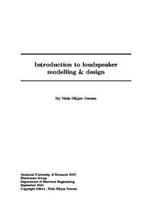
…ASIC Styles Sample ASIC floorplan: CPU ‘core’
Standard Cell ‘rows’ Datapath
ROM
RAM
• Standard Cell designs are usually synthesized from an RTL (Register Transfer Language) description of the design • ASIC design is much quicker than full custom design • A full set of masks is still required for fabrication
©2000, Dr. Paul D. Franzon, www.ece.ncsu.edu/erl/faculty/paulf.html
7
ECE 520 Class Notes
…ASIC Styles 3. Gate-Array Based ASICs • In a gate array, the transistors level masks are fully defined and the designer can not change them • The design instead programs the wiring and vias to implement the desired function • Gate array designs are slower than cell-based designs but the implementation time is faster as less time must be spent in the factory • RTL-based methods and synthesis, together with other CAD tools, are often used for gate arrays.
©2000, Dr. Paul D. Franzon, www.ece.ncsu.edu/erl/faculty/paulf.html
8
ECE 520 Class Notes
…ASIC Styles 4. Programmable Logic Devices (PLDs) • are off-the-shelf ICs that can be programmed by the user to perform various functions (usually just combinational logic functions) • The simplest PLD is an EPROM • There are no custom mask layers so final design implementation is a few hours instead of a few weeks • Simple PLDs are used for simple functions
9
©2000, Dr. Paul D. Franzon, www.ece.ncsu.edu/erl/faculty/paulf.html
ECE 520 Class Notes
…ASIC Styles 5. Field Programmable Gate Arrays (FPGAs) • Off-the-shelf chips that the user programs to perform simple functions • Can be quite complex, capable of implementing 100,000s of gates • Some companies call them ‘complex PLDs’ • e.g. XILINX: Configurable Logic Block (CLB): Programmable Interconnect Array:
Source: XILINX Application notes ©2000, Dr. Paul D. Franzon, www.ece.ncsu.edu/erl/faculty/paulf.html
10
ECE 520 Class Notes
Research Project….Data Programmable Cache New Ideas •Cache lines and FPGA lines alternated •Cache lines can be used as •Cache for embedded CPU •Store FPGA configurations •Store data for FPGA •FPGA can switch to any of 4 ‘contexts’ in one clock cycle Impact •2x performance over •FPGA •FPGA + SRAM
Mouna Nakkar 11
©2000, Dr. Paul D. Franzon, www.ece.ncsu.edu/erl/faculty/paulf.html
ECE 520 Class Notes
Decision Making Alternative implementation approaches: • Program a PC or a microcontroller
l (some microcontrollers have high-performance 32- or 64-bit CPUs) • Build a full custom, cell-based or gate array ASIC • Use a PLD or FPGA Approach Design Manufacturing Manufacturing Productivity NRE cost/unit (gates/day) + lead time Cell200 $50k 1x based (full mask set) 8 weeks Gate 200 $10k ~1.2x Array < 1 week
FPGA
500
$0 1 day
©2000, Dr. Paul D. Franzon, www.ece.ncsu.edu/erl/faculty/paulf.html
~5x
Clock frequency 1x
~0.8x ~0.3x
12
ECE 520 Class Notes
…Decision Making Other Issues: • Design tools and design training
l Cell-based ICs require more investment but give more capable designs • Time to Market
l Profits increase dramatically with every month shaved off time-to-market (about 30%/3-months, according to one study)
l Approaches: u Consider using an FPGA for product introduction, or at least prototyping u Enhance design productivity as much as possible Ð people, tools, training, methods and techniques
l Good design verification is very important for Cell-based ICs
©2000, Dr. Paul D. Franzon, www.ece.ncsu.edu/erl/faculty/paulf.html
13
ECE 520 Class Notes
ASIC Design Methology Most ASICs are designed using a RTL/Synthesis based methodology • Design details captured in a simulatable description of the hardware
l Captured as Register Transfer Language (RTL) l The two most common RTLs are Verilog and VHDL • Automatic synthesis is used to turn the RTL into a gate-level description
l ie. AND and OR gates, etc. l Chip-test features are usually inserted at this point • Physical Design tools are then used to turn the gate-level design into a set of chip masks (for photolithography) or a configuration file for downloading to an FPGA • At each stage, extensive verification is performed. ©2000, Dr. Paul D. Franzon, www.ece.ncsu.edu/erl/faculty/paulf.html
14
ECE 520 Class Notes
Summary ASIC Design Flow HDL Design Capture Design Specification
Behavioral Description
RTL Description
Simulation Vectors
RTL Functionality
No
Verified?
•Its often useful to write a behavioral simulatable specification •Captures intent well •Gives an independent source of verification vectors 15
©2000, Dr. Paul D. Franzon, www.ece.ncsu.edu/erl/faculty/paulf.html
ECE 520 Class Notes
…ASIC Design Flow HDL Design Synthesis
Yes RTL to Logic
Constraints
Logic Optimization
Logic to Technology
Constraints
Back annotation of timing data
Timing/Area Optimization
Insert Scan Chains Test vector gen.
Netlist/SDF Functionality/Timing
No
Verified? Yes
©2000, Dr. Paul D. Franzon, www.ece.ncsu.edu/erl/faculty/paulf.html
16
ECE 520 Class Notes
…ASIC Design Flow Yes
Design Implimentation
Floor Planning
Place & Route
Back annotation of timing data Physical Layout
Layout Functionality/Timing Verified?
No
Yes Chip Production ©2000, Dr. Paul D. Franzon, www.ece.ncsu.edu/erl/faculty/paulf.html
17
ECE 520 Class Notes
Visual view of Tool Flow for ECE 520 ECE 492B / ECE 520 ASIC Design Objective: Learn how to design a digital ASIC using Register Transfer Languages (Verilog), modern synthesis tools (Synopsys) and modern verification and back end tools (Cadence). Learn how the tools constrain and permit modern design. Survey ASIC architectures and conduct a project in multimedia or communications.
©2000, Dr. Paul D. Franzon, www.ece.ncsu.edu/erl/faculty/paulf.html
18
ECE 520 Class Notes
Future Tool Issues Growing Chip Complexity
l 10M+ transistors/chip very close l combined with a shortage of designers, and need for shorter design turnaround times Ù Design Reuse l Components designed to be reused in other designs l A methodology for fast integration of library-based designs Increasing importance of wiring
l Wiring parasitic capacitance increasing faster than gate capacitance
l leads to wiring having a strong effect on delay and noise l Often referred to as the “deep sub-micron” problem because its importance becomes pronounced at gate sizes below 0.18 µm.
l Solution:
l Short term: More tightly integrated tool flows, better estimators l Medium term: Combined logical and physical synthesis
©2000, Dr. Paul D. Franzon, www.ece.ncsu.edu/erl/faculty/paulf.html
19
ECE 520 Class Notes
Summary •
Over the next ten years, product growth will be driven by:
l Continued explosive growth of the internet l Insatiable demand for graphics and multimedia l Insidious insertion of electronics and computers into our everyday lives • Many of the resulting products will require specialized silicon chips to meet performance (speed/size/weight/power/cost) demands - ASICs • To match this product need, the capability of a silicon CMOS chip will continue doubling every 2-3 years until after 2015.
l To sell a product at $300-$1,000, it can only include one high value chip
u Thus product performance is determined by the performance of that one chip
l AND talk about planned obsolescence!!
• ASIC styles include full custom (for analog) and RTL-based design: Cell based (semi-custom), Gate Array or FPGA implementation • ASIC design methodology includes logic, timing, and physical design
l Unfortunately, design productivity is not keeping up with chip performance growth ©2000, Dr. Paul D. Franzon, www.ece.ncsu.edu/erl/faculty/paulf.html
20