Introducing service differentiation into IEEE 802.11 Imad Aad and Claude Castelluccia PLANETE team, INRIA Rh6ne-Alpes. ZIRST - 655, Avenue de 1'Europe. 38330 Montbonnot Saint Martin - France [imad.aad, claude.castelluccia] @ inrialpes.fr, http://www.inrialpes.fr/planete.html
Abstract
In this paper we propose mechanisms for user differentiation in wireless environments. The paper is organized as follows: Section 2 describes the 802.11 protocol. Section 3 presents simulations and analysis of the 802.1 1 when used with TCP and C B W D P traffic sources. Section 4 introduces some ways of service differentiation on the wireless with some simulations. Finally, section 5 gives some hints for future work and section 6 concludes this paper.
The IETF is currently working on service differentiation f o r the Internet. However service differentiation at the IP layer is useless without support of lower layers. This support is even more critical in wireless environments because of the dynamism of the channel conditions and of the network topology. In this paper we present a service differentiation support for the IEEE 802.11. The idea is to scale the contention window according to the priority of eachJlow or user. Preliminary simulation results are shown when using this mechanism with TCP and UDR
2 IEEE802.11 The IEEE 802.1 1 standard covers the MAC (Medium Access Control) sub-layer and the physical layer of the OS1 (Open System Interconnection) reference model. In this paper, we only focus on the MAC part. A general description of the IEEE 802.1 l standard is available in 141, it supports two services: Distributed Coordination Function (DCF) and Point Coordination Function (PCF). In the first mode, Wireless Terminals (WTs) have to content for use of the channel at each data packet transmission. In the second (optional) mode, the medium usage is controlled by the Access Point (AP), polling the WTs to access the medium, thus eliminating the need for contentions. The DCF is an asynchronous data transmission function, which best suits delay insensitive data (e.g. email, ftp). It is the only possible function in ad-hoc networks, and can be either exclusive or combined with PCF when used in an infrastructure network (equipped with an AP). The PCF best suits delay sensitive data transmissions (e.g. realtime audiohideo). The basic scheme for DCF is Carrier Sense Multiple Access (CSMA). This protocol has two variants: Collision Detection (CSMNCD) and Collision Avoidance (CSMNCA). A collision can be caused by two or more stations using the same channel' at the same time after waiting a channel idle period, or (in wireless networks) by two or more hidden terminals2 emitting at the same time.
1 Introduction Wireless communications are an emerging technology and are becoming an essential feature of everyday's life. Not only computer networks are becoming mobile, eventually each device will have a wireless interface (e.g. laptops, cameras, phones etc.) [ I]. Simultaneously, multimedia is having an equivalent growth: from data to voice up to video communications. Some of these applications impose requirements on some communication parameters, such as bandwidths, drop rates, delays and jitters in order to work properly. Exceeding these requirements either decreases considerably the communication quality or even deteriorates it completely. Using multimedia in a mobile environment shows a critical situation, due to the properties of radio links, such as interference, fading etc. These parameters are also more variable than in a wired or fixed environment, which calls for adaptive protocols or for robust control algorithms, but this last is not optimal when the channel conditions are good. To deal with these problems, many wireless communication standards have been defined. Some of them enhance the Quality of Service (QoS) of the whole system [ 5 ] , others differentiate between the priorities of each mobile host, offering them different quality of service parameters (e.g. different bandwidths or delays etc.)[9].
'On the physical layer, in spread spectrum technology, a channel is the pseudo-random sequence used to "spread" data. 2hidden terminals are terminals which cannot hear each other [3].
438
0-7695-0722-O/OO $10.00 0 2000 IEEE
d.
.
DIFS
Time
I
DIFS
I
NAV (RTS) NAV (CTS)
I+
I1 CanL wm
Figure 1. Basic access scheme.
Figure 2. RTS/CTS access scheme.
CSMNCD is used in Ethernet (IEEE 802.3) wired networks. Whenever a node detects that the transmitted signal is different from the one on the channel, it aborts transmission, saving useless collision time. This mechanism is not possible in wireless communications as WTs cannot listen to the channel while transmitting, due to the big difference between transmitted and received power levels. In this case, after each frame transmission the sender waits for an acknowledgment (ACK) from the receiver, as shown in Fig. 1. Source axis shows data transmitted by the source. The destination responds by an ACK, represented on the Destination axis. The third axis represents the network state, as seen by Other WTs. Note that transmission delays are not shown. The Interframe Spacings DIFS and SIFS will be explained later in this section. If no ACK was returned, a collision must have occurred and the frame is retransmitted. But this technique may waste a lot of time in case of long frames, keeping transmission going on while congestion is taking place (caused by a hidden terminal for example). This can be solved by introducing an optional RTSKTS scheme (Request To Send and Clear To Send respectively), in addition to the previous basic scheme. In the optional RTSKTS scheme, a station sends an RTS before each frame transmission for channel reservation. The destination responds with a CTS if it is ready to receive and the channel is idle for the packet duration. When the source receives the CTS, it starts transmitting its frame, being sure that the channel is “reserved” for the frame duration. All other WTs update their Network Allocation Vector (NAV) at each hearing of RTS, CTS and the data frames. NAV is used for virtual carrier sensing, detailed in the next paragraph. This scheme is shown in Fig. 2. The overhead caused by the transmission of RTSKTS frames becomes considerable when data frames sizes are small, and sub-optimal channel usage takes place. References [ 3 , IO] discuss optimal data frame sizes (RTS-Threshold) above which it is recom-
mended to use the RTS/CTS scheme. Not all packet types have the same priority. For example, ACK packets should have priority over RTS or data ones. This is done by affecting to each packet type a certain Inter Frame Spacing (IFS) before which a packet cannot be transmitted, once the channel becomes idle. In DCF two IFSs are used: Short IFS (SIFS) and DCF IFS (DIFS), where SIFS is shorter than DIFS (See Fig. 1 and 2). As a result, if an ACK (affected with SIFS) and a new data packet (affected with DIFS) are waiting simultaneously for the channel to become idle, the ACK will be transmitted before the new data packet (the first has to wait SIFS whereas the data has to wait DIFS.) Carrier sensing can be performed on both layers. On the physical layer physical carrier sensing is done by detecting any channel activity caused by other sources. On the MAC sub-layer, virtual carrier sensing can be done by updating a local NAV with the value of other terminal’s transmission duration. This duration is declared in data frames, RTS and CTS frames. Using the NAV, a WT MAC knows when the current transmission will end. NAV is updated upon hearing an RTS from the sender andor a CTS from the receiver, so the hidden node problem is avoided. The collision avoidance part of CSMNCA consists of avoiding packet transmission right after the channel is sensed idle (+ DIFS time), so it won’t collide with other “waiting” packets. Instead, a WT with a packet ready to be transmitted waits a random time after the channel being idle for DIFS, backoff time, shown in Fig. 1 and 2 . Backoff time of each WT is decreased as long as the channel is sensed idle (during the so called contention window): When the channel is busy, backoff time is freezed. When backoff time reaches zero, the WT transmits its frame, but if the channel is sensed busy because of another “waiting” frame, the WT computes a new random backoff time, with a new range. This range increases exponentially as 22+i where i (initially equal to 1) is the transmission attempt number. Therefore, the backoff time equation is:
43 9
121
-
1 -
I
08-
-
06-
e
.
I
.
..
..i
j
.
f 0
04
-
02
-
'
"
I
nv13 0.023955 mer3 a111673
0
1
Figure 4. Delays using CBR.
Figure 3. Throughput using CBR.
Backoffdime = L22+i x rand()] x Slot-time
exceed the effective radio link bandwidth i.e. 1.6 Mbps in our simulation. In this example a single traffic overloads the link, sending 1100-byte packets each 0.005 seconds (giving a bandwidth of 1.76Mbps > I .6Mbps, so the channel is busy most of the time). As shown in Fig. 3 , WT1 has a stable throughput, it also has short delays and jitters. The drop rate depends on the used bit rate (about 10% in our case). During the second phase (i.e. between seconds 100 and l50), WTl and WT2 share the bandwidth almost equally as they both have the same probability to access the medium (Fig. 3 ) . The average delays (Fig. 4) of both traffics are higher (for WT1 it goes from 0.27 to 0.55 seconds) than the first period due to a higher number of RTS failures. Jitter also gets higher due the more variable channel conditions. In the third period, between seconds 150 and 250, WT3 shares the medium with the previous two. Throughput gets lower, as bandwidth is shared among the three WTs. Delay, jitter and drop rate get higher.
where Slot-time is function of some physical layer parameters, and rand() is a random function with a uniform distribution in [0,1]. There is a higher limit for retransmission attempts i, above which the frame will be dropped. Collision avoidance is applied on data packets in the basic scheme, and on RTS packets in the RTS/CTS scheme. All WT have equal probability to access the channel, thus share it equally. But this method has no guarantees for queuing delays, so it is not optimal for time-bounded applications. Time-bounded applications are better supported with the optional PCF.
3 CBR and TCP over 802.11 In this section, we present simulation results and analyze the behavior of two traffic source types when running over an IEEE 802.1 1 MAC sub-layer: CBR3 (Constant Bit Rate) and TCP (Transport Control Protocol)[6]. The topology of the simulation4 network is rather simple: Three WTs, denoted by WTi where i = l,2 and 3 respectively, are uniformly distributed around an AP and they are sending their packets to a fixed host wire-attached to the AP.
3.2 TCPflows When we replace the CBR traffic sources with TCP ones, the throughput, delay, jitter behave the same way as before. However packet dropping due to buffer overflow at the sender is avoided with TCP. We observe absolutely no TCP dropped packets due to its adaptivity and to the use of RTSKTS scheme: When the sender requests to transmit and the channel is idle, no dropping is observed as long as the traffic is adapted to the offered throughput, which is the case of TCP. Some RTSs encounter collision, are dropped, then retransmitted by the MAC sub-layer transparently to the TCP layer.
3.1 CBRflows Let us first consider the use of a CBR traffic source.
WT1,WT2 and WT3 start sending their packets at seconds 50, 100, and 150 respectively, using the RTS/CTS scheme. Simulation ends at second 250. During seconds [50,100[, WT1 can have the desired bandwidth as long as it doesn't 31n fact it is a CBR source over a UDP (User Datagram Protocol)[S] transport layer, but we simply say CBR for convenience. 4using NS (Network Simulator).
440
awl 9402 2w
!
’
80
100
120
140
160
180
’drw-mh3.
-.--
sw259214.4
j
60
’drop-mnl’ ’drop-mhi?’
.
(4701%) m e 124.32 (6247%)
2W
220
240 Tlme(s
50
1W
150
I
avl2 147631736%) wr3: 154.45 (77.22%)
2M
I
250 Time (sec)
Figure 6. Drop rates using CBR with priorities.
Figure 5. Throughput using CBR with priorities
4.1 Backoff increase function
4 Proposal As we have seen in section 2, As mentioned in the introduction, in order to give WTs some QoS guarantees we can offer differentiated services between WTs by offering them different QoS parameters. Before getting into details, let us define how to compare Prioritization Functions (PF) and give an example. Consider PF and PF’ applied in the same conditions. We say that PF performs better than PF’ regarding a given QoS parameter if the system using PF is as efficient as when using PF’ (or maybe better), as stable as with PF’ and if PF gives a wider range of relative priority than PF’ (the range starting from 1). This criterium can be applied on the system QoS parameters: Bandwidth, drop rate, delay, and the jitter5. If we look at introducing priorities in the IEEE 802.1 1 , several parameters can be considered, among which:
BackoflAime = L22+i x rand()] x Slot-time the only configurable term in this equation is 22+i. Our first attempt to introduce priority was to replace it by Pj2+* where Pj is a priority factor of the station j . So, instead of multiplying the range by two at each transmission attempt failure, we multiply it by Pj. (Here, the higher the priority factor is, the larger the backoff range is, the lower is the chance to access the channel, the lower is the bandwidth.)
4.2 CBRflows We used this scheme in the same network configuration as section 3. WTs send CBR packets, using the RTSKTS scheme. At time 50, WTl starts transmission with a priority factor P1=2 (WT2 and WT3 are then idle) then at time 100, WT2 starts transmission with P2=6. Finally, at time 150, WT3 starts transmission with P3=8. The AP uses a priority factor of 2. The results are shown in Fig. 5 and 6. When only WTl is on, it uses the whole link bandwidth, exactly as in the case with no priorities (in section 3). When WT2 goes on (at time IOO), the link is unequally shared between the two, WTI having a higher bandwidth share (1.42:l). At time 150, the third WT goes on and the results are similar. Obviously, we can change the ratios Pi/Pj (i # j ) to have other bandwidth shares, and have a wide range of shares (so better priorities). But as this range increases (high priority ratios) the system becomes unstable, showing more bandwidth variability and higher jitters. This instability is more visible with low priority traffics (high priority factors, as WT3). From the bandwidth point of
1. Backoff increase function: Each priority level has a different backoff incrementation function.
2. Backoff decrease function: Each priority level has a different backoff decrementation function.
3. Maximum frame length: Each priority level has a maximum frame length allowed to be transmitted at once.
4. DIFS: Each priority level is assigned a different DIFS, after which it can transmit its RTS or data packet. We’ll analyze the first and the fourth, and show simulation results for the first one. The rest is left for future work. 5We consider that the jitter is the standard deviation of the delay.
441
than with CBR, as shown in table 1. Using TCP, the channel has been detected idle 12100 times (96.08%), and for 3 (0.02%) times, it had 4 consecutive busy channel sensings which lead to a 255 value contention window sizes. When using CBR, the channel was sensed idle 12096 (94.04%) times, and it reached higher contention window sizes (5 11) for 2 times, due to 5 consecutive busy channel sensings. CBR does not rely on ACKs to generate its packets, and so it is “independent” of the MAC sub-layer as this kind of synchronization is absent. CBR will constantly generate its packets and the number of unsuccessful idle-channel sensings is high, leading to higher contention window sizes. This shows why introducing priorities in the backoff time incrementation has lower effect on TCP than on CBR, in other words, for the same Pi/Pj used with TCP and CBR, the resulting relative priority range width is much higher with CBR.
Table 1. Contention window distribution for TCP and CBR Cont. Win. Size (min)31 63 127 255 51 1 (max)1023
using TCP 12100 (96.08%) 462 (3.67%) 29 (0.23%) 3 (0.02%) 0 0
using CBR 12096 (94.04%) 685 (5.33%) 69 (0.54%) 1 1 (0.09%) 2 (0.02%) 0
view, the system efficiency gets slightly better when using more WTs, due to more sensing , “filling” more channel idle periods and getting the channel more busy (compare the bandwidths of WT1, WT1 and WT2 together, and all three WTs in Fig. 3. ( a v q uvr2 avr3)150-250 > ( a v q + ~ v T 2 ) 1 0 0 - 1 5 0 > ( a v ~ 1 ) 5 0 - 1 0 0>.These bandwidth sums will remain almost the same after introducing the priority scheme. (Compare the sum of the bandwidths of each period, before and after introducing the priority scheme i.e. Fig. 3 and 5.)
+
4.3
+
5
Future work
The results presented in this paper are preliminary. Future work should address the following issues: Combined TCP-CBR flows: Preliminary simulations show that when we apply the backoff priority mechanism on various flows (in various WTs) simultaneously:
TCPflows
Note that when we replace CBR by TCP, the results are quite different: they show no considerable prioritization effect, and all three WTs almost equally share the bandwidth. In fact, TCP is an adaptive transmission protocol based on the feedback control embedded in the reception of ACK packets. In both Slow Start and Congestion Avoidance periods, TCP sends new data packets only at ACK reception. This gives two reasons why using BackoffAme is not convenient for differentiating TCP flows, which limits our approach: First, the AP sends all TCP-ACKs, for all WTs using the same priority (the highest in our simulations) as our differentiation is on a per station basis, not per flow basis. To solve this problem, the last case assumes that the AP looks in the header of each packet to check the destination addredport. This gives additional load for the AP. It could be also the case that differentiation is per packet, which supposes that each packet has a priority field which sets the differentiation parameters (similar to DiffServ [7]). The additional field causes overhead problem for short packets. These approaches are left for future work. Second, this ACK reception synchronizes the TCP packet generation with channel idle periods (while other WT sources are still waiting for their ACKs.) This increases the number of successful idle-channel sensings because the probability of having the channel idle after the reception of an ACK is high, leading to lower contention window sizes
- A CBR flow with high priority won’t have considerable advantage over a TCP flow with lower priority, and the common channel bandwidth is equally shared. In fact, for the “synchronisation” reason explained above, the backoff priority scheme won’t be used effectively by TCP flows, and so their priority cannot be reduced.
- On the other hand, when we apply the priority scheme on a WT with high priority using TCP flows, and another with low priority using CBR flows, high priority TCP flows get more throughput than low priority CBR ones. Backoff priorities enhance the TCP throughput without necessarily enhancing the cwnd size, as the RTT is considerably reduced relative to the nonpriority scheme. Higher RTS-Threshold values, so packet shorter than RTS-Threshold may collide. P e r j o w / p e r packet differentiation. Deeper analysis of the Backoff differentiation mechanism: how must the priority of a frame change when the channel is sensed busy? Mapping D i B e r v to MAC differentiation. [2]
442
6 Conclusion This paper presents some preliminary results of our work on introducing service differentiation mechanisms into IEEE 802.1 1. We propose a scheme based on the contention window, The idea is to scale the contention window according to the priority of each flow or user. We show via simulations that our scheme performs well with UDP but does not work with TCP traffic. In fact TCP congestion window mechanism avoids mobile hosts to go into a backoff mode. A host always finds the medium available when it has to transmit a packet. Besides, ACK packet of different WTs are sent with the same priority, as our differentiation is per transmitting station. The main contribution of this paper is to show that service differentiation based on contention window scaling schemes, function of the transmitting terminal only, does not perform well when used with TCP. But for differentiating multimedia application flows, which mostly use UDP, this scheme performs well. It is also the case when we need to prioritize TCP flows over UDP ones, by lowering the UDP flows priority.
RR IRaadomRange
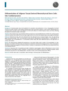
Figure 7. Including priority in DIFS
0
Building admission control schemes.
e
Modeling the system, can give us a better description which may allow to build optimal priority functions, wider relative priority ranges while still working in a stable system.
0
D1FS:We have seen in the previous paragraphs that using backofflime to differentiate between wireless users do not apply to TCP flows. An alternative solution would be to use DIFS for differentiation.
References
As shown in section 2, IEEE 802.11 ACK packets have higher priority than RTS packets, simply by waiting SIFS which is shorter than DIFS (for RTS). We'll use the same idea to introduce priorities for data frames (in the basic scheme) and for RTS frames (in the RTSKTS scheme). In this approach we give to each priority a different DIFS, say D I F S j where DIFSj+I < D I F S j . So the WTs having priority j will wait DIFSj idle period before transmitting the packet. And to avoid same priority frames collision, the backoff mechanism is maintained in a way that the maximum contention window size added to D I F S j is DIFSj-I - D I F S j as illustrated in Fig. 7.
[ l ] Specgcation
of
the
Bluetooth
System.
http://www.bluetooth.com/. [2] T. Braun, C. Castelluccia, G. Stattenberger, and I. Aad. An
analysis of the DiffServ approach in mobile environments. http://www.inrialpes.fr/planete/people/MobiQoS/paper2.ps,
unpublished, April 1999. [3] H. S. Chhaya and S. Gupta. Performance modeling of asynchronous data transfer methods of IEEE 802.11 MAC protocol. Wireless Networks, 3 , 1997. [4] B. P. Crow, 1. Widjaja, J. G. Kim, and P. T. Sakai. IEEE 802.11 Wireless Local Area Networks. IEEE Communicatiun Magazine, September 1997.
[5] A. W. E H.P. Fitzek. QoS support in wireless networks using Simultaneous MAC Packet Transmission (SMPT). In ATS, April 1999. http://www-tkh.ee.tuberlin.deibibl/ours/W WWATS.ps. [6] V. Jacobson. Congestion avoidance and control. In Pruceedings of SIGCOMM '88,pages 314-329, August 1988. [7] K. Nichols, S. Blake, E Baker, and D.Black. Dejnition of the Diflerentiated Services Field in the IPv4 and IPv6 Headers. Request For Comments 2474. [8] J. Postel. User Datagram Protocol. Request For Comments 768. [9] L. Taylor. HIPERLAN white paper, June 1999.
This will ensure that no WT of priority j+l has queued frames when WT of priority j starts transmission. Low priority traffic will suffer as long as there are high priority frames queued. It could also be the case that the maximum random delay after D I F S j can be made greater than DIFSj-1 - D I F S j , so the previous rule becomes less severe. This PF offers a very wide range of relative priority: It can be a 1:I when DIFSs are equal and RRs are equal. The relative priority can be infinite when D I F S j 2 (DIFSj+l+RRj+l).We believe that this mechanism do not use the contention window to introduce service differentiation should work for CBR and TCP types of flows.
http://www.hiperlan.com/. [lo] J. Weinmiller, H. Woesner, J. Ebert, and A. Wolisz. An-
alyzing the RTSICTS Mechanism in the DFWMAC Media Access Protocol for Wireless LANs. In IFIP TC6, 1995.
443