10 COMBUSTION
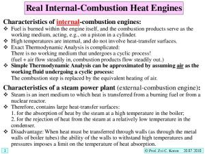
INTERNAL ENGINES - RECIPROCATING 10.1 Introduction Heat engine in which the combustion of.fuel takes place in the engine cylinder is known as internal combustion engine. As the combustion takes place inside the engine cylinder, very high temperature is produced in the cylinder. It is therefore, necessary to abstract or remove some of the heat from the cylinder to prevent damage to the metal of the cylinder, by circulating water through jacket, surrounding the cylinder. The cylinder of a motor cycle or an aero-engine is cooled by atmospheric air. It may be noted that the cylinder of a steam engine requires to be heated by supplying steam (from the boiler) in the jacket surrounding the .cylinder to reduce condensation of steam in the cylinder. The thermal efficiency of an internal combustion engine is much higher than that of a steam engine plant, as in I.C. engine there is no apparatus corresponding to boiler and no losses corresponding to the boiler losses. A best modem I.C. engine converts about 30 to 35 per cent of the heat of combustion of fuel into work (i.e. the thermal efficiency is about 30 to 35 per cent), whereas an ordinary steam engine plant converts only 8 to 10 per cent and a best modem steam turbine plant converts .only 15 to 25 per cent of heat of combustion of fuel into work, i.e., the overall efficiency of a modem steam plant (boiler and turbine combined) is about 15 to 25 per cent. Reciprocating internal combustion engines are most ,commonly single-acting whereas reciprocating steam engines are nearly always double-acting. All large size I.C.'engines and marine I.C. engines are double-acting. As the combustion of fuel takes place inside the engine cylinder of internal combustion engine, they are relatively smaller in size as compared to steam engine plant. A steam engine plant needs a boiler, a condenser, * and an economiser. Internal combustion engine can be started quickly within a short time, whereas a steam engine plant will require much more time as steam has to be generated in the boiler before the steam engine can be started. Around 1878, many experimental I.C. engines were constructed. The first really successful engine did not appear, however, until 1879, when a German engineer Or. Otto built his famous Otto gas engine. The operating cycle of this engine was based upon principles first laid down in 1860 by a French engineer named Mr. Bea be Rochas. The majority of modem I.C. engines operate according to these principles. The development of the well known Diesel engine began about 1893 by Mr. Rudolf Diesel. Although this engine differs in many important aspects from the Otto engine, the operating cycle of modern high speed Diesel engines is thermodynamically very similar to the Otto engines.
302
ELEMENTS OF HEAT ENGINES Vol.l
10.2 C lassilication Internal combustion engines may be classified according to the : - Type of fuel used - Diesel oil engine, Petrol engine, Gas engine, and Light oil (Kerosene) engine. - Nature of combustion - Otto or Constant Volume combustion cycle engine, Diesel or Constant pressure combustion cycle engine and Dual-combustion cycle (combustion partly at constant volume and partly at constant pressure) engine. -
Cyde of operation (number of strokes required to complete each cycle) - Two-stroke cycle engine and four-stroke cycle engine. zx. Inlet Exhaust valve - Method c f igniting fuel- Spark valve ignition (S.I.) engine, and Compression ignition (C.l.) engine. Exhaust -
-
Method of fuel supply to the engine cylinder - Carburettor engine, Air injection engine, and Solid or Airless injection engine.
Cylinder head Piston Cooling fins
Arrangement of cylinder Horizontal engine, Vertical engine, V-type engine, and Radial engine.
- Speed of the engine - Low speed engine, Medium speed engine, and High speed engine. - Method of cooling the cylinder - Air cooled engine and Water cooled engine. - Method of governing the engine - Hit and miss, Quality, and Quantity governed en^
C onnecting ro d
Crank case
C ran k sh a ft
Crank pin
Fig. 10-1. Cross-section ot ait cooled, single cyliudei, single-acting, vertical petrol engine.
- Application of the engine- Stationary engine, Portable engine, Marine engine, Automobile engine, Tractor engine, Locomotive engine and Aero engine. - Number of cylinders - Single-cylinder engine, Twin-cylinder engine and multi-cylinder engine, etc. - Action of product of combustion upon the piston - Single-acting engine and Double-acting engine. - Suction pressure - Naturally aspirated engine and Supercharged engine. The engine shown in fig. 10-1 is commonly known as petrol engine, but it can be more properly described as : 20 B.H.P., petrol, Otto four-stroke cycle, spark ignition, single-cylinder, single-acting, vertical, high speed, air cooled, quantity governed, stationary engine.
INTERNAL COMBUSTION ENGINES-RECIPROCATING
303
10.3 Engine Parts and Terms Internal combustion engines have one or more cylinders in which combustion of fuel takes place. A cross-section of an air cooled, single-cylinder, petrol engine (Otto cycle engine) with principal parts is shown in fig. 10-1. One end, i.e., top end of the cylinder is closed by means of a cover known as cylinder head as shown in fig. 10-2, which contains the inlet or admission valve for admitting the mixture of air and petrol into the cylinder, an exhaust valve for removing the products of combustion (exhaust gases) from the cylinder, and a spark plug for igniting or exploding the mixture of polrol and air.
Rocker arm
Fig. 10-2. Section of a vertical, air-cooled cylinder of a petrol engine.
Fig. 10-3. Cam and rocker mechanism for opening and closing air and exhaust valves.
The two valves are kept closed by means of springs and are opened mechanically by means of levers or rocker arms and cams as shown in fig. 10-3. The cams are fitted on the camshaft. The camshaft is driven by the crankshaft through gear wheels fitted on each shaft. The passages in the cylinder head leading to and from the valves are called ports. If the inlet ports of the various cylinders of a multi-cylinder engine are connected to a common inlet pipe of engine, the pipe is called the inlet manifold. If the exhaust ports are similarly connected to a common exhaust pipe, the pipe is called the exhaust manifold. The piston shown in fig. 10-2 is a gas tight movable cylindrical disc which slides up and down in the cylinder against which the combustion pressure acts, to cause the crankshaft to rotate by means of connecting rod which is connected to the piston at the other end. The piston is given a gas tight fitting in the cylinder by means of piston rings shown in fig. 10-1.
304
ELEMENTS OF HEAT ENGINES Vol.l Piston pin
The connecting rod (figs. 10-1 and 10-4) connects the crank pin with the piston and transmits the force due to the pressure of the \ Big end cylinder gases on the piston head, bearing down to the crankshaft To provide for the swinging operation of the Fig. io-4. Connecting rod. connecting rod, the upper (small) end of theconnecting rod is fitted to thepiston by means of cylindrical pin called the piston pin orgudgeon pin orw rist pin (figs.10-1 and 10-4). The lower (big) end of the connecting rod is fitted to the crank pin (figs. 10-1 and 10-5). The crankshaft is the principal rotating part of the engine. This shaft transmits the reciprocating motion of the piston to the driven unit (say electric generator) in the form of rotating motion. This shaft is built with one or more eccentric portions Fig. 10-5. Crankshaft of a multi-cylinder engine. called cranks. Crankshaft with two cranks is shown in fig. 10-5. The part of crank to which the big end of connecting rod is fitted, is called crank pin. The main body of the engine which contains the crankshaft and main bearings, is called the crankcase (fig. 10-1). This part hold (supports) the crankshaft and other engine parts in alignment (in line) and resists the explosive and inertia forces produced during working of the engine. The piston in fig 10-2 is shown in top dead centre position which is the top most position of the piston during upward movement. At this position piston comes to rest. The piston travels from top dead centre to a point near the bottom end of the cylinder, called bottom dead centre. The distance the piston travels during one stroke, from top dead centre to bottom dead centre, is called the length of stroke or piston stroke. The inside diameter of the cylinder is called the bore. The volume swept by the piston during one stroke, i.e., while moving from top dead centre to bottom dead centre, is called the displacement volume of the cylinder. The volume or space between the piston and the cylinder head, when the piston remains at the top dead centre position, is called the clearance volume. This clearance space forms the combustion chamber where the combustion of mixture of fuel and air takes place. Some familiarity with the terms and functions of parts explained above is necessary for understanding the basic principles of engine operation. The other important parts, namely, fuel pump, fuel injector (fuel valve), carburettor, electric-spark ignition system, and governor will be described later in the chapter. The following sequence of events (operations) is required to take place in any I.C. engine to complete the cycle : .. The mixture of gas or fuel vapour and air in correct proportion in the case of gas or petrol
INTERNAL COMBUSTION ENGINES-RECIPROCATING
305
engine, or pure air only in the case of Diesel engine, must be supplied to the engine cylinder. .. The mixture of fuel and air in case of petrol engine, orpure air only in case of Diesel engine, must be compressed in the engine cylinder during the compression stroke, and in Diesel engine the fuel must be pumped into the cylinder through the fuel valve when compression of air is complete. .. The compressed mixture of fuel and air in case of petrol engine or fuel oil in case of Diesel engine must be fired when compression is complete. In case of petrol engine the moderately compressed petrol-air mixture is fired by an electric spark, and in Diesel engine the fuel oil is fired when it comes in contact with highly compressed hot air at the end of compression stroke. .. The resulting pressure rise, due to combustion of fuel and the expansion of combustion products, drive the piston out (i.e. the piston moves away from the dead centre) on its power stroke and rotates the crankshaft. The crankshaft in turn drives the machine connected to it. .. When the expansion of combustion products is complete, the burnt-out gases must be cleared or removed from the engine cylinder to make room for fresh mixture of fuel and air in case of petrol engine or only air in case of Diesel engine to enter the cylinder. 10.4 Cycles of Operations In any internal combustion engine, all the above mentioned operations for completing a cycle are carried out either in two strokes or four strokes. If an engine requires four strokes of the piston or two revolutions of the crankshaft to complete the cycle of the operations, it is termed a four-stroke cycle engine. If on the other hand, the cycle of operations is completed in two-strokes of the piston or in one revolution of the crankshaft, the engine is termed a two-stroke cyde engine. Further any I.e. engine will work on one of the following three combustion cycles : — Constant volume combustion or Otto cycle, — Constant pressure combustion or Diesel cycle, and — Partly constant volume and partly constant pressure combustion or Dual-combustion cycle. These may be operated on either two-stroke or four-stroke cycle. In Otto engines mixture of fuel and air is compressed to a moderate pressure of about 700 to 800 kPa (to prevent pre-ignition of the mixture during the compression stroke) and mixture is ignited by means of an electric spark while the piston remains on, or close to, the dead centre so that ignition takes place theoretically at constant volume. Petrol, gas, light oil (paraffin or kerosene), and heavy oil engines work on this cyde. In petrol and gas engines, the mixing of fuel and air takes place outside the cylinder (petrol is vapourised and mixed with air in correct proportion in the carburettor in case of petrol engines) and then the mixture is drawn in the cylinder during the suction stroke. In light oil engines, the fuel is vapourised and converted into vapour outside the cylinder by spraying oil into the vapouriser which is heated continuously by exhaust gases of the engine and then the mixture is drawn during the suction stroke. In heavy oil engines, the oil is vapourised by spraying oil into hot bulb or hot combustion chamber which is fitted on the top of the cylinder. In this case, the mixing of fuel and air is done in the cylinder before the compression of mixture starts. The hot combustion chamber requires heating by stove only at the time of starting the engine. H E I - 20
3™
= *
f 20 ^ 100
(2 2 100
m
where d i = diameter of piston rod, and d - cylinder diameter Indicated power on the cover side ■ pm x a\ x I x n
m
INTERNAL COMBUSTION ENGINES-RECIPROCATING
333
» 19,450 W i.e. 19-45 kW Indicated power on the crank side
= pm x % x / x n 20 100
= (645 x 103) x J
( 2-2 ^ 100
^ 30 A 100
= 21,063 W or - 21 063 kW As the engine is double-acting, total indicated power = Indicated power on cover side + Indicated power on crank side* = 19-45 + 21 063 - 40-513 kW Brake power
=
{W - S) R x 2nN
where (W - S) = net load on the brake wheel
=1,324
R = effective brake wheel radius =
1
2
N = revolution per second made by theengine
- 131 = 1,193 N, = 0-51 m, and = 7 r.p.s.
Brake power - 1,193 x 0-51 x Zn x 7 = 26,760 W or 26-76 kW Mechanical efficiency = 7
Indicated power
40-513
= 0-6605 or 66-05%
Problem-5 : A four cylinder four-stroke cycle petrol engine is to be designed to give a brake power of 185 kW at 35 r.p.s. The stroke bore ratio is to be 1.5 to 1. Assuming a mechanical efficiency o f 75 per cent and indicated mean effective pressure of 830 kPa, determine the required bore and stroke. Indicated power =
Brake power Mechanical efficiency
0-75
= 246 67 kW i.e. 2,46,670 W
jn d ica t^jjo w e r _ pm x / x a x n (indicated power per cylinder) n 2,46,670 ,00_ . - 3. i.e. ——i — = (830 x 10 ) x -
4 100
4
1-5d 35 x — — x — 100 2
2,46,670 x 4 x 104 x 102 x 2 = 5,405 4 x 830 x 103 x 3 14 x 1 5 x 35 Diameter of cylinder, d = $5,405 = 17-54 cm Piston stroke, r = 1-5 d = 1-5 x 17-54 = 26-32 cm. Problem -6 : The following readings were taken during the test on a single-cylinder four-stroke cycle oil engine : Cylinder diameter, 19 cm; stroke, 35 cm; gross mean effective pressure, 748 kPa; pumping mean effective pressure, 36 kPa; engine speed, 240 r.p.m. fuel used per hour 35 kg, calorific value of fuel oil, 46,000 kJ/kg. Determine : (i) the indicated mean effective pressure, (ii) the indicated power, and (iii) the indicated thermal efficiency of the engine. (i) Gross m.e.p. * 748 kPa; Pumping m.e.p. = 36 kPa. Using eqn. (10.3b),
334
ELEMENTS OF HEAT ENGINES Vol.l Net indicated mean effective pressure. pm = 748 - 36 = 712 kPa
(ii) Using eqn. 10.3(a), Indicated power = pm x a x / x n = (712 x 103) x .
100
35 4 x —~ x 100 2
= 14,124 W or 14124 kW. (iii) Here, Indicated power = 14-124 kW, Wf = 3-5 kg/hr and C.V. * 46,000 kJ/kg. Heat equivalent of indicated power = 14-124 kJ/sec. Heat supplied = g £q q
x
46,000 = 44-722 kJ/sec,
, .. , . .. . . Heat equivalent of indicated power in kJ per sec. indicated thermal efficiency, iu = -------- 3— r:—:------- ;;- . r ; , -------------- c-------1 1 Heat supplied in kJ per sec. =
14-124
= 0-3158 or 31 58%
Problem-7 : In a test on a single-cylinder oil engine working on the four-stroke cycle and fitted with a simple rope brake, the following readings were taken : Brake wheel diameter, 60 cm; brake rope diameter, 2-5 cm; dead load on the brake, 200 newtons; spring balance readings, 30 newtons; speed, 8 r.p.s.; area of the indicator diagram, 420 m rrr; length of indicator diagram, 60 mm; spring used had a stiffness of 110 kN/rr? per mm elongation; diameter of the cylinder, 10 cm; stroke, 15 cm; fuel used, 032 kg/kW/hour on brake power basis of calorific value 44,000 kJ/kg. Calculate the brake power, indicated power, mechanical efficiency and indicated thermal efficiency of the engine. Effective radius of the brake wheel, R =
= 31-25 cm = 0-3125 m
(where D = Diameter of brake wheel in m, and d = diameter of brake rope in m) Using eqn. (10.4a), Brake power » (IV - S)
x 2n x R x N
where (W - S) = Net load on the brake wheel = 200 - 30 = 170 N, N = r.p.s. = 8 and R - Effective radius of the brake wheel = 0-3125 m Substituting the above values in eqn. (10.4a), Brake power = 170 x 2rc x 0-3125 x 8 = 2,670 W = 2-67 kW Using eqn. (10.2), indicated mean effective pressure, area of the indicator diagram ^ -----; 9---------- x pm = ----- rm length of the indicator diagram
r spring number
420 = x 110 = 770 kPa 60 Indicated power = pm x a x / x n W = (770 x 103) x |
f 10 100
Using eqn. (10.5), Mechanical efficiency,
\2
X
100
X I = 3,627 W or = 3 627 kW 2
INTERNAL COMBUSTION ENGINES-RECIPROCATING t|m =
335
Power - = -2~Y= = 0-7316 or 7316% Indicated power 3-627
Fuel consumption per hour = 2-67 x 0-32 = 0-854 kg/hr. .*
Using eqn. (10.7), Indicated thermal efficiency, _ Heat equivalent of indicated power in kJ/sec. “ Heat supplied to engine in kJ/sec. =
= 3,600
X
44,000
= 0-3475 or 34-75% 10 437
Problem-8 : The following data and test results refer to a test on a single-cylinder two-stroke cycle oil engine : Indicated m.e.p., 550 kPa; cylinder diameter, 21 cm; piston stroke, 28 cm; engine speed, 6 r.p.s. brake torque, 628 N.m; oil consumption, 816 kg/hr; calorific value of oil, 42,700 kJ/kg. Calculate: (a) the mechanical efficiency, (b) the indicated thermal efficiency, (c) the brake thermal efficiency and (d) brake specific fuel consumption in kg/kW/hr. (a) Indicated power = pm x a x / x N 21
= (550 x 103) x -J Brake power = (W — S)
28 x -™ x 6 = 32,000 W or 32 kW
100
FI x 2k N = T x 2itN W
where T = (W - S) R - Brake torque = 628 N.m, N = r.p.s. = 6, and 2nN = number of radians per second = 2n x 6. Substituting the above values, we have, Brake power = 628
x 2 x 314 x 6 = 23,663 W or 23-663 kW
Mechanical efficiency = ~ 1 Indicated power 32
= 0-7398 or73-98%
... . Heat equivalent of indicated power in kJ/sec. (b) Indicated thermal efficiency = — z rrn z iL - ; ; , ; --------' ’ Heat supplied to the engine in kJ/sec. Heat equivalent of indicated power = 32 kJ/sec. Heat supplied/sec. =
8* 16
x
Indicated thermal efficiency =
( v 1 kW - 1 kJ/sec.)
42,700 kJ/sec. 32
x 100 =
3306%
£ & >
Brake speo.no fuel consumption (B.S.F.C, . = J “ g = 0 3449 kg/kW/hr.
ELEMENTS OF HEAT ENGINES Vol.1
336
Problem-9 : The following data was obtained from a trial of an single-cylinder gas engine working on the four-stroke cyde and governed by hit and miss method of governing; Diameter of cylinder, 18 cm; stroke, 38 cm; effective brake radius, 74 cm; indicated mean effective pressure, 440 kPa; average revolutions per second, 3; average explosions (working cycles) per minute, 82; net load on the brake, 235 newtons; gas used per hour, 4 2 m ; and calorific value of gas, 15,490 kJ/m3. Calculate : (a) the indicated power, (b) the brake power, (c) the indicated thermal effidency and (d) gas consumption in m3 per kW per hour based on brake power. (a) Indicated power ■ pm x a x / x n (where n - no. of explosions per sec.) =
x
(4 4 0
x ^
1 0 3)
/ J 8 \2 100
38
X
82
x —
100
60
= 5,810 W or = 581 kW (b) Brake power = (W - S) R x 2nN = 235 x
x 2 x 3-14 x 3
=* 3,277 W or 3 277 kW 5*81 —-
(c) Indicated thermal efficiency, =
3 ,6 0 0
(d) Gas consumption in m
*
= 0-3215
or 32-15%
1 5 '4 9 0
per kW Hr. on brake power basis
= “ §= = 1 28 m3/kW Hr. W'bI ( Problem-10 : The following data and test results refer to a four-stroke cycle oil engine : Number of cylinders - 4; bore - 10 cm; stroke = pressure » 670 kPa; speed = 34 r.p.s.; brake-torque 1289 kg/hr; calorific value of fuel oil = 42,000 kJ/kg.
15 cm; indicated meaneffective - 185 N.m; oil consumption =
Calculate : (a) the brake power, (b) the brake thermal effidency, (c) the spedfic fuel consumption on brake power basis (B.S.F.C.), (d) the indicated power, (e) the mechanical effidency of the engine, and (f) the brake mean effedive pressure. (a) Using eqn. (10.4c), Brake power = T x 2n x N where T = Brake-torque = Brake power =
185
x
2k
x
185
34
=
N.m and N 3 9 ,5 2 0
W or
= r.p.s. = 3 9 -5 2
34
kW
(b) Using eqn. (10.9a), Brake thermal efficiency, _ Heat equivalent of brake power In kJ/sec. ~ Heat supplied to engine in kJ/sec. 39 52 I 2- 8® x 4 2 ,0 0 0
39 52
0 .2 6 2 8
or
26 28%
150 38
3 ,6 0 0
(c) Specific consumption,
fuel
consumption
B.S.F.C. = ! | | 1 = 39-52
0 326
on brake power basis or Brake specific fuel
kg per kW per hr.
337
INTERNAL COMBUSTION ENGINES-RECIPROCATING (d) Indicated power per cylinder = pm x a x I x n = (670 x 103) | x
15 34 '10 '2 100 X 100 X 2
= 13,140 W or 13-41 kW Total indicated power of four cylinders (engine) = 13-41 x 4 - 53-64 kW (e) Mechanical efficiency, rim = ---- = f —f f = 0-7367or 73-67% ' 7 1 Indicated power 53-64 39-52 (f) Brake power per cylinder = — . - = 9-88 kW Using eqn. (10.4d), Brake power = b.m.e.p. x a x I x n where b.m.e.p. = brake mean effective pressure in kPa, a = area of the piston in m , I = length of piston stroke in m, and n = no. of working strokes per sec. i.e. 9-88 x 103 = b.m.e.p. x ^
10 100
15 34 x 77^; x — 100 2
b.m.e.p. per cylinder = 4,94,000 Pa or 494 kPa Alternatively Brake mean effective pressure (b.m.e.p.) = Indicated mean effective pressure x Mechanicalefficiency = 670 x 0-7367 = 494 kPa (same
as
before)
Problem-11 : A single-cylinder, four-stroke cyde oil engine is to develop 31 kW at 300 r.p.m. If the indicated mean effective pressure is 675 kPa and speed of the piston is 183 metres per minute, what is the diameter of cylinder and piston stroke ? If the indicated thermal effidency of engine is 30 per cent and the calorifc value of the oil is 42,000 kJ/kg, what is the fuel consumption in kg per kW per hour on indicated power basis ? Piston speed in m/min. = 2IN [where I = length of piston stroke in m, and N = number of revolutions ofthe engine/min. (r.p.m.)] i.e. 183 ■ 2 x I x 300 .-. Piston stroke, I = 0-305 m Using eqn. (10-3a), Indicated power = pm x 3 x I x n i.e. (31 x 103) = (675 x 103) x ~
_d_ 100
x 0-305 x
300 60 x 2
.-. D2 = 767-27 .*. Diameter of the cylinder, d = V767-27 = 27-67 cm. Using eqn. (10.7) and taking indicated power as 1 (one), Indicated thermal effidency, r|/ = H E I -* 22