The Piston Engine Revolution
Gas Producers for Internal Combustion Engines: Ancient and Modern D. Andrews and F. Starr Gas producers have been used as a source of energy for large stationary gas engines from the earliest days of the IC piston engine. The paper reviews the history of the gas producer, but also comments on automotive vehicles fitted with gasifiers. Some examples of running costs for stationary engines are given. The paper describes a recent wood based gasifier project that fuelled a modified 250 kW natural gas engine. The problems encountered give an insight into the operation of gas producers of the past. KEYWORDS: gasification, producers, fuels, automotive, modern types. Gasification Processes The terms pyrolysis and gasification are used here in the following way:
Pyrolysis is the heating of coal or wood in the absence of air, thereby driving off volatile combustible gases, leaving coke as a residue, as in the original town gas process (or charcoal if wood is employed). The gaseous products contain methane, hydrogen, carbon monoxide with some carbon dioxide and nitrogen. In addition the gaseous pyrolysis products contain tars, liquid hydrocarbons, phenols and ammonia liquors, which condense out at ambient temperatures. Pyrolysis occurs between about 400-1000°C1 Gasification is today referred to as the partial combustion of coal, coke or wood, in which as much as possible of the fuel is turned into a gas. The main “gasification” reactions, which occur between about 700-1400°C are: C+O2 = CO2 CO2+C = 2CO H2O + C = CO + H2
(1) (2) (3)
It will be apparent that the volume of gas produced by pyrolysis, as in town gas manufacture, where much of the coal remains as coke, is significantly less than that produced from the same tonnage of coal in a gas producer. This is the basic reason why producers were built, instead of town gas being purchased from the local gas company. In a producer type gasifier, reaction (1) is one of normal combustion, which produces carbon dioxide and supplies the heat for reactions (2) and (3). These are
342
The Piston Engine Revolution
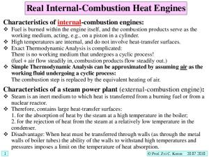
endothermic. Heat is also needed for any pyrolysis of the fuel which may occur, and for driving off any moisture in the fuel. The pyrolysis of wood, at around 1000°C, will produce a gas similar to coal gas. Most commercial pyrolysis of wood (sometimes referred to as destructive distillation) was done at temperatures under 500°C, the main aim being to produce chemicals such as methanol, creosote and turpentine. 2 Figure 1 shows a schematic of an updraft gas producer and the reaction zones and temperatures at various bed heights. Basically there are three layers. The topmost, being the pyrolysis zone, is where the newly added coal begins to heat up and pyrolysise. The intermediate layer is where, following passage through the pyrolysis bed, the coal has transformed to coke and where CO2 and steam reacts to form CO and H2. The bottom zone is where the remaining coke burns out to produce an ash. Wyer suggests that the height of the fuel bed, excluding ashes, should be no more than six feet, otherwise channels are likely to form, resulting in CO2 and steam from the combustion zone of the bed bypassing the intermediate coke layer.3
Figure 1: Reaction zones in an updraught gas producer.
Wyer implies that deeper beds are feasible if mechanical “pokers” are used. 4 One would therefore suppose that channelling is a result of the coal forming a thick semi-plastic mass in the pyrolysis zone, tending to seal off the bed and preventing
343
The Piston Engine Revolution
gaseous products from escaping. Accordingly a deep bed would result in an excessively thick pyrolysis zone through which, here and there, channels would form. Once formed, the channels would burn down towards the combustion zone and this is where gas flow would be concentrated. Depending on the type of gasifier and the fuels provided, gas compositions vary widely. In an engine, fuels of a high calorific value give the highest efficiency and provide the highest power output. These are not necessarily the most economic. Table 1, most of which refers to the period up to the First World War, gives gas compositions and calorific values for a variety of fuel gases, all of which, in principle, could be used to power gas engines. 5 Today, IC engines and combined cycle gas turbines used for power production are fuelled with North Sea Gas, which is almost 100% methane. 6 The type of gas generated from producers is usually called “producer gas” when made from coal or coke, and “wood gas” when made from wood. It is largely carbon monoxide with some hydrogen plus the inert gases nitrogen and carbon dioxide. Its calorific value is about a seventh of that of natural gas. Today there are gasifiers, using thousands of tonnes of coal a day, which operate under pressure, usually with pure oxygen as the oxidising agent. The modern gasifiers closest in form to the gas producers of this paper are termed “moving bed” gasifiers. One of these, the Lurgi gasifier, is a large-scale pressurized gas producer, in which the mineral matter in the coal forms an ash. Table 1 Gas Compositions (%) and Calorific Values
Blast Furnace
H2 CO CO2 CH4 CnH2n N2 Btu/ft3 MJ/m3
Suction Gas Producer
Pressure Producer
NH3 Recovery
No NH3 Recovery
Coke Oven Gas
Town Gas
North Sea Gas
Coke
Coal
Coke
Coal
Coal
Coal
Coal
N/A
1 28 12 ----59 95 3.54
15.6 20 6 1.1 --57.3 124 4.62
14 25 6.4 ----54,6 124 4.62
26 11 16.9 2.7 --43.4 140 5.21
17 23 5 3 --52 157 5.85
52 7.5 5.5 21.5 1.5 2 415 15.5
43 10 33 4 10 560 20.6
----0.2 94.4 3.9 1.5 1037 38.6
It was first put into use in 1936. In the British Gas development of the Lurgi gasifier (the BGL), temperatures in the hearth zone are high enough to melt the ash, which is removed as a slag. In effect, the BGL gasifier is much the same as a blast furnace. The main differences are that coal, rather than coke, iron ore and limestone, are charged to the gasifier and an automatic technique is used to tap off the slag from the base of the gasifier, rather than it being removed manually from
344
The Piston Engine Revolution
the side. The Higman and v.d Burgt reference gives a comprehensive account of modern day high-pressure gasification processes.7 Early History of Gas Engines and Gas Producers Efficiency Issues and Engine Development The proportion of energy in the producer gas, (referred to as the cold gas efficiency) compared to that in the coal, appears to have stabilised at around 75%, once designs had become established. This is quite similar to modern high-pressure gasification processes. Hence any reductions in fuel consumption in the gas producer/engine combination had to come from development of engines; in particular, compression ratios were increased. Table 2 shows that the efficiency of Crossley engines improved from 17% to 25% between 1882 and 1894, giving a 32% reduction in fuel consumption.8 These efficiency figures are just above half the values as calculated from the air standard efficiency formula. The 1894 Crossley was not much worse than most modern stationary gas engines, at least up to ten years ago (today’s engines utilize variants of the Atkinson and Miller cycles and can reach efficiencies in the 40% plus range). Table 2. Improvement in Gas Engine Efficiency Date 1882-88 1888-94 1894
Compression Ratio 3.6 5.5 6.9
Efficiency 17% 21% 25%
Air Standard Efficiency 33% 40% 43%
Town Gas and Gas Engines It is generally recognized that the world’s first commercial gas works was built in Great Peter Street, London, in 1812 and was based on the pyrolysis process developed by Murdoch, although an earlier private installation was in 1807 in a mill in Salford. Town gas became widespread in the UK and the rest of Europe and because of its explosive and inflammable character was perceived to be a suitable fuel for engines of the internal combustion type. Up to then the focus had been on hydrogen as a fuel. At the 1867 Paris World Exhibition the Otto and Langen free piston engine was awarded the Grand Prize. Although crude and noisy, the Otto and Langen was commercially successful, but in 1876 the four-stroke “Silent Otto” was introduced. Thereafter gas engines were widely used in many applications in preference to steam. These early engines all ran on town gas. They had the benefit of needing lower manning levels than a steam engine. However town gas was costly. Its chief use was for lighting, in which a primitive type of burner produced a luminous flame, needing a gas which
345
The Piston Engine Revolution
contained aromatic constituents, as well as methane and hydrogen. The luminosity indicates that the gas had a fairly high calorific value, probably about half that of natural gas, and allows us to make some estimates of the fuel cost of running a gas engine. We also use the fact that in 1878, in response to the growth of gas monopolies, the UK Parliament established that a fair price for gas would be 3 shillings and 3 pence (£0.16) for 1,000 cu ft.9 On the basis that the calorific value of one cu ft of gas was about 500 kJ, a pound’s worth of gas would have an energy content of 3125 MJ. If a gas engine had an efficiency of 20%, and this amount of gas was burnt in a fifty-hour week, engine output would be 3.5 kW. In Victorian times a ton of coal cost about £0.50. This would give about 30,000 MJ of primary energy. A steam engine of just a few horsepower would have an efficiency under 3%, including boiler losses. Accordingly a pound’s worth of coal, burnt over a week, would produce about 9 kW. Thus the fuel for the gas engine costs about three times as much as that for steam. But the gas engine avoided the need for an engine-man/stoker, who even in Victorian times would have expected to be paid £0.75 a week. In addition the gas engine had no start up and shut down time. Hence it is easy to see why even the Otto and Langen was so attractive, despite its noise and vibration. Four-strokes were even better. With steam engines of higher output, efficiency was in the 10% range, thus reducing fuel consumption by 3.3 times and fuel costs, compared to gas engines, by a factor of ten or more. Manpower costs at this size were trivial. Dowson states that the crossover point, when a steam engine was more economic than a gas engine running on town gas, was 20 hp which does seem to be a little on the high side. 10 Nevertheless, the need for a cheaper fuel was paramount, if the gas engine was to progress, and producer gas was the answer. But in turn, the gas engine helped stimulate the development of the gas producer. Even without this up-and-coming technology, there was a growing market for producer gas as a heating medium, as it was cleaner and could be more economic than burning coal to make steam. Early Gas Producers and Fuels The concept of “gas producers” was in the air before 1850, but it is generally agreed that it was Wilhelm Siemens who was really responsible for introducing the concept, as a means of producing an inflammable gas for firing his glass and openhearth steel furnaces. The Siemens gasifier was of industrial scale, with the hot gas being sent directly to the burners. 11,12 Figure 2 shows a schematic of the Siemens Producer, in which an ingenious technique was used to ensure that a good draught was induced through the bed of coal, without the use of a fan or blower. The temperature of the producer gas as it leaves the producer is about 400°C. It then turns into a horizontal section, followed by a vertical “downcomer” (E) before the gas is sent to the burners. The downcomer section consists of a free standing, cast iron duct, exposed to the air,
346
The Piston Engine Revolution
and in this section the gas temperature falls to about 100°C, increasing in density. The difference in density between the gases in the upcoming and downcoming sections of the producer creates a pressure difference that “pulls” the gases through the system. There was no attempt made to clean the gases, since a certain amount of tar and particulates increased the radiating power of the flame. However, much of the tar was deposited on the sides of the ductwork and was burnt off periodically.
Figure 2. Early version of the Siemens Gas Producer
The first gas producer of more general use was that developed by Dowson in 1878, in which the gas was cooled and cleaned to some extent. 13 Figure 3 is a schematic showing the producer as a fairly small vertical brick-lined cylinder on the left. It contains a bed of anthracite, which is fed from the top. Air, and some steam, enters the cylinder at the bottom, burning out the remaining portion of the coal, and leaving nothing but ashes. A jet of superheated steam from an external boiler is used to help draw the air into the fuel bed and produce a gas with higher hydrogen content and a slightly improved calorific value. The gas exits the bed at about 400°C. Although not shown in the diagram, the gas enters a small water scrubber. The main scrubber, which contains coke, is housed inside a gasholder, which is an intrinsic part of the Dowson plant. Unlike the Siemens producer, which did not incorporate storage, the gasholder allowed work to start and stop at any time.
347
The Piston Engine Revolution
Figure 3 : Schematic of Dowson Gas Producer.
It took some time for engine builders to recognize that producer gas could be used for gas engines, although Dowson did a trial with a 3 hp Otto in 1878. These tests were repeated by Dugald Clerk on the same engine some years later; he found that the overall fuel consumption was less than 2 lb of coal per horsepower hour.14 At that time steam locomotives, which are non-condensing, were typically running at over 4 lb/hp.hr. Another issue was tar and dust in the gas. Although Dowson had incorporated a large scrubber into his unit, he minimized the tar problem by using anthracite or coke. But anthracite, the “top-rank” of the coals, was not always available and was twice the cost of bituminous coal. Fortunately wide-scale town gas manufacture had resulted in the production of large quantities of coke as a byproduct. Nevertheless, the lower price and availability of bituminous coal led to continued efforts to overcome the tar problem and was a major reason for the development of the downdraught gasifier. Dugald Clerk, however, mentions that coke was not a very satisfactory fuel in the Dowson Producer, without giving any reasons. Perhaps the main difficulty was with getting the coke to ignite and keeping it burning at low loads. It obviously was an issue, since Clerk quotes some tests using an early Crossley engine of 120 ihp. During the eight-hour test, the producer used 584 lb of anthracite, and 140 lb of coke was used to raise steam in the boiler. 15 The rate of anthracite consumption was quite small, roughly 1lb/min and, given the input of steam, and
348
The Piston Engine Revolution
because some of the reactions are endothermic, it would be fairly easy to “put the fire out”. Wood gas producers seem to have been confined to places and times where there was a shortage of coal, or where there was much wood waste, as in the Bryant and May Match Factory in Liverpool, which saved 11 tons of coal a day. There was a similar installation in Halifax. A major issue with wood was the moisture content, which needed to be kept below 10%. Through the need to evaporate trapped moisture, energy was wasted in the producer, resulting in a high content of CO2 and a gas of a low calorific value. Equipment made by companies such as Crossley and Campbell were intended to utilise sawdust-like material from wood fabricating operations. Here the intention was to turn as much as possible of the waste wood into gaseous energy for powering IC engines, Figure 4 and 5. Others like those made by Sawtelle Inc, were intended to produce useful liquid products such as methanol, creosote and turpentine. These plants had an elaborate set of tubular copper condensers acting as crude fractionating columns, the temperature of the gas dropping as it progressed through the unit. The Sawtelle gasifier required the wood to be chopped into small blocks about one inch square and a quarter inch thick, which helped to get consistent conditions. 17
Figure 4 Crossley Wood Gas Producer.16
Updraught, Suction and Downdraught Producers All the early examples of gas producers were of the “updraught type”, in which the air flowed upwards through the producer. The term updraught is often used synonymously with the steam or pressurised producer, but suction producers are
349
The Piston Engine Revolution
Figure 5 Cross-section of Crossley Wood Gas Producer.
also of the updraught type. The steam or pressurised form came to be confined to situations where the gas was used for heating. Here, the hydrogen in the gas was no problem, and it ensured easier ignition of the gas. Pressurisation was achieved by the steam flowing through a Giffard-type injector, which drew in a supply of air. 18 An injector of this type can be seen to the left of the Brooke and Wilson producer, shown in Figure 6.
Figure 6 : Brooke and Wilson Steam Injected Gas Producer of 1876.
350
The Piston Engine Revolution
The invention of the suction producer was a direct result of the introduction of the four-stroke cycle in which, on the induction stroke, a partial vacuum forms in the inlet pipe work. The reduced pressure was used to pull the producer gas into the engine and this in turn induced air into the gasifier. This eliminated the need for the combustion air to be pressurized. The airflow and producer gas output are directly proportional to power developed by the gas engine. However it was still normal to add some steam to the air to keep the ash cool and control bed temperatures. The steam generated was at atmospheric pressure and was superheated to prevent condensation and wetting of the fire. Unfortunately this method of introducing steam resulted in complications; at low outputs when the flow of air was reduced, some method of reducing the steam flow was needed. There were other drawbacks to the suction producer. The producer gas, being put under a partial vacuum, had lower volumetric energy content and there was some reduction in temperature, resulting from the fall in pressure which, because the gas was saturated, having come through a scrubber, could lead to the precipitation of moisture. Figure 7 shows a cross section through a Dowson suction producer, and is much more sophisticated than that shown in Figure 2. 19 The effective top of the bed is below the place at which coal is loaded and the producer gas is taken off through the pipe “G”. Since a fairly uniform flow of coal entered the bed, this is likely to have reduced the production of tars.
Figure 7. Dowson Suction Producer.
351
The Piston Engine Revolution
The combustion air enters the gasifier through the port “F”, into an annular chamber “C” which surrounds the top of the furnace. The chamber contains firebricks, which become heated and serve to preheat the combustion air; and since they are sprayed with water coming from a ring “D”, the chamber also produces steam. Later models of suction gas producers used a centrifugal blower to draw the gas from the producer and through the scrubbers, but were not an option until electric power became widely available. Figure 8 shows an example, intended for use with bituminous coal, from a sales catalogue of 1926.20 It also gives brief constructional details of a Campbell producer for anthracite, coke or charcoal. Even with these fuels, which are far less likely to agglomerate than bituminous coal, it is stated that, to avoid clogging the bed, the fuel size should be greater than 12 mm for anthracite and coke, and 19 mm for charcoal.
Figure 8. Late Model Campbell Suction Gas Producer.
A major shortcoming of all forms of updraught producer was the formation of tars, which was a result of the hot gases from the lower parts of the bed pyrolysing the coal that had just entered the gasifier. The flow in the downdraught producer drew the tar laden gases down through the bed where, on entering the high temperature zone, the tars cracked, producing lighter hydrocarbons and some carbon. Ideally, these too would be consumed. In practice it was difficult to ensure that the lower portions of the bed could be kept hot enough to achieve this. One possibility, when coal was used as a fuel, was to inject air into the lower part of the bed, or alternatively to have, in effect, a separate bed consisting of coke which was kept hot by blowing through it a stream of air and steam. Although the downdraught system eliminates tars, the producer gas emerges from the gasifier at a very high temperature. This heat has to be recovered and utilized for steamraising, etc, otherwise efficiency suffers. Modern wood-based systems avoid this
352
The Piston Engine Revolution
problem by ensuring that the bed is kept open, by controlling of the size of the wood fuel. This permits sufficient air to reach the bottom of the bed and keep the fuel, which at this point is charcoal, red-hot. Gas Producer Design and Operational Aspects Wrangham gives some basic data on gas producer design and operation.21 The amount of fuel which could be burnt was just under 100 kg/m2/hr of grate area. The bed depth for the combined combustion and reduction zones was 0.75 m for anthracite and 1.5 m for bituminous coal. The ash zone was to be 0.6 to 0.9 m deep, so as to keep the grate cool. Operating at too high a temperature increases CO2 levels and reduces the calorific value of the gas. The only way to verify temperature was to insert an iron bar through the poker holes into the bed and then to withdraw it rapidly. If it was white hot, the rate of steam injection needed increasing. Wrangham mentions what even in past times was a serious issue. On leaving the producer, the gas entered a downcomer pipe in which the gas was sprayed with water, to remove as much tar as possible. The bottom of the downcomer entered a sump full of water, which became foul and was a serious disposal issue. Large-Scale Power Production Blast Furnace Gas In many ways a blast furnace can be considered to be an updraught gasifier that produces vast quantities of low calorific value gas. Enormous long stroke piston engines, some as much as 6 MW, were built to utilise this fuel. The main difference between a blast furnace and a standard producer is that hard coke is used as a fuel, in which all the volatile constituents have been driven out, during the coke making process. The coke, so produced, is strong enough to support the “burden” of coke, iron ore and limestone without crushing. The bed is therefore permeable to the gases that are produced in the blast furnace hearth. These engines drove reciprocating compressors producing a blast pressure of about 10 psi (c.0.7 bar). A more detailed description of the engine technology is given by Lawton, who states that Thwaites in 1894 was the first to utilise blast furnace for this purpose.22 Lawton points out that on the Continent it was customary to build very large single cylinder machines, which in turn would have driven large reciprocating blast furnace blowers. In the UK, engine makers began to adopt the higher speed, multi-cylinder type of design, which is now the standard approach. The main problem with blast furnace gas is dust.23 Most of this would have come from the grinding together of the lumps of coke as they were dropped into the furnace during charging, and then when the lumps moved down within the furnace itself. These particles were removed by using fairly crude inertial techniques. The heaviest particles dropped out of the gas at the bottom of a long
353
The Piston Engine Revolution
downcomer leading from the top of the furnace. The medium-sized particles then went through boxes containing baffle plates, in which the gas was subject to abrupt changes in direction. The most difficult particles to eliminate were those that appeared after the blast furnace gas was burnt in boilers or in the Cowper stoves. This material appeared as a “white smoke…..which may stretch for miles across the landscape”. It seems probable that the main constituents of this dust were quicklime from decomposition of the limestone and alkali compounds such as K2CO3 and KCN from the reduction of alkali-bearing materials in the coke and iron ore. These were very detrimental to engines and had to be removed in washing towers, and then in a type of centrifugal separator. Gas Engines for the Supply of Electricity About the time the gas engine came into use, the world was turning to electric power generation. The early power stations used large slow-moving steam engines, which needed to be equipped with large flywheels to ensure constant voltage (most electricity supply before 1900 was direct current, so frequency control was not an issue). It seemed that power generation using gas engines had a good future. Dowson states that the first gas-powered units were at Dessau in Germany, initially with a 60 hp engine, the unit being part of the local gas works, using town gas. 24 The first plant specifically mentioned to be using producer gas was at Schwabering in 1889, powering 10 arc lamps and 300 incandescent lamps. At this scale the average small steam plant was not very efficient. Dowson called attention to the very high rates of coal consumption of steam engines in the 10-100 horsepower range. He stated that typical figures were around 6 lb per horsepower.hour, but this would be bituminous coal rather than anthracite. Even so, this would be 3 to 4 times higher than a gas engine. The first public supply in Britain using gas engines was that of the Morecambe Electric Light Power Company, which went into operation in 1882. 25 Three engines of 25 hp ran for a very short time on town gas, but were then operated off Dowson producers. Speed regulation was by a combination of throttle and cut-out (hit and miss) governing. The gasholder held reserves for only ten minutes operation, hence the producers had, in theory, to vary their output. In practice, engines and producers were always run at full output and surplus power was stored in a battery bank. As indicated below, part load efficiencies were not ideal. With anthracite at a cost of 18s/ton, the fuel cost, was a halfpenny per kWh (£2.08/MWh). But the overall cost, including distribution, was £29.2/MWh. The site had to be moved after a few years because of complaints about fumes and noise, and was then converted to steam. It appears that the first really successful installation was that of the Midland Railway for lighting the station and good yards at Leicester.
354
The Piston Engine Revolution
One of the last installations to be built was that belonging to Walthamstow Urban District Council, Figure 9, and was subsequently referred to, in somewhat sardonic terms, by Parsons, writing from the perspective of 1939. 25 The Walthamstow plant opened in 1901 and was gradually extended, but after 1907 developments were all based on steam. Power was for public electric lighting and the borough tramway service. Westinghouse built the gas engines and the gas plant was a Dowson steam-jet type producer running on anthracite. The station had an aggregate power of 2275 bhp (1.7 MW), although the biggest engines were no more than 250 bhp. A thousand amp-hr battery was used to help balance the load.
Figure 9. Gas Producers and Engines at Walthamstow Urban District Generating Station c.1905.
Figure 10. Proposed 8MW Power Generation Plant.
Sir John Snell, a pioneer of power generation in Britain and the British Empire, gave a balanced review of power generation in the period before the First World War, discussing several examples, including a proposed 8MW plant of seven engines and eight gas producers. 26 Figure 10 shows a side view of this plant and one of the lines of producers, tar separation systems and engines.
355
The Piston Engine Revolution
A major issue with early power plants was the poor load factor. During the early 1900s most of the demand came from indoor lighting, daytime business and tramways. At night the demand vanished completely. In the 8MW plant described above the estimated load factor was 24%, which may account for the expected station efficiency of just 12%. Gas engines had some advantages over reciprocating steam engines. A gas producer could be kept warm for very little outlay of fuel and could be got to maximum output within about 20 minutes. The combination of the gas producer and engine was more efficient than steam engines of a similar output. Table 3 gives the fuel consumption of medium sized Crossley engines and producers. At 100% load, with anthracite coal, the consumption was equivalent to an efficiency of 21.4%. With bituminous coal the best figure was 15.8%, presumably because of the loss of energy in tars and other condensables. Part load efficiencies down to about 50% were still quite creditable, but at 25% load specific fuel consumption doubled. Reciprocating steam engines for power generation were fairly efficient by the standards of the time. Snell indicates that steam consumption for medium-sized engines of about 300 hp was around 18 lb/kWh. Steam conditions, with the engines he described, were 13.4 bar and 276°C, which gave an engine efficiency of 15.3%. However, with a boiler efficiency of 80%, this gives a coal-to-power efficiency of 12.2%. Thus the gas engine is marginally better when working at full load. The drop in efficiency of the steam engine at reduced power was however far smaller than the gas engine. At quarter load, the thermal efficiency reduced only by about 30%. Table 3. Fuel Consumption (lbs/hp.hr) of Crossley Engines of 73-260 bhp Calorific Value 100% 75% 50% 25% Fuel Btu/lb Load Load Load Load Anthracite 14800 0.82-0.80 0.92-0.90 1.11-1.1 1.63-1.59 Coal Bituminous 13000 1.25 1.4 1.72 2.48 Coal Coke or 12400 0.98-0.95 1.1-1.07 1.35-1.3 1.95-1.9 Charcoal Waste Wood 7000 2.0 2.22 2.76 3.9 “dry” Efficiency is one aspect of engine operation, but it is overall costs that determine the choice of equipment. The following table adapted from Snell shows that it is only at high load factors that the gas engine starts to become competitive. A major reason for this is that the cost of anthracite was £1.10 per ton, compared to bituminous coal at £0.50 per ton. Capital costs for both types of plant were broadly
356
The Piston Engine Revolution
similar. Snell points out that that a diesel engine is worth considering when the load factors are very low, even through fuel cost was £2.10 per ton. 27 Table 4. Comparison of Overall Electricity Costs for Gas and Steam Engines Annual Load Factor % 20 30 40 50 60
Gas Engine £/MWh 3.17 2.48 2.09 1.87 1.69
Steam Engine £/MWh 2.80 2.23 1.93 1.75 1.63
It appears that for the public supply of electricity, generation using gas engines was a dubious option. Parsons, in his 1939 review, stated that the history of gas engines for generating electricity was little better than a record of failures. Noise and vibration were continuing issues. And although gas engines were more efficient than the steam engines of the time, the cost of anthracite wiped out any economic benefit. The question rapidly became irrelevant with the development of steam turbines, when both gas and reciprocating steam engines, with their paraphernalia of slow moving, massive flywheels and alternators, became consigned to the dustbin of history. Industrial Use of Gas Engines In the period before the First World War and before current-carrying wires had reached all parts of the UK, some manufacturing companies were using gas engines for on-site power, as it was more competitive than steam. For example Rankine Kennedy refers to gas engines at Messrs Andrews Ltd of Stockport, probably around 1905.28 The works had their own gas producer and a gasholder of 6000 cu.ft capacity. The Andrews’ works contained a number of engines totalling 69 ihp. The working week was 53 hours, with the engines actually running for 55 hours. Gas consumption was 67 cu. ft/ ihp, so during a week the gas consumption for all the engines was about 250 thousand cu.ft. A ton of coal produced 160,000 cu.ft of gas, at a cost of £1.25. Andrews’ coal cost, per week, was therefore £1.95. Weekly costs were as follows, including interest and depreciation at 10%. Coal Labour (one man) Oil and waste for engines Interest, depreciation and repairs
357
£1.95 £1.25 £0.20 £1.80
Total
£5.20
The Piston Engine Revolution
If the mechanical efficiency of the engines is about 80%, then the power produced during a week was 2,925 hp.hr or about 2,200 kWh. It follows that the cost was £2.36/MWh at 1905 prices. Adjusted for inflation this gives a figure of £22/MWh, about twice the current domestic rate. Net thermal efficiency was over 23%, which seems a little high, but Andrew’s costing is in line with those given in Table 4. Presumably the company did not have to pay distribution charges. Other companies used gas engines where they had some type of waste fuel. The Bristol Aeroplane Company was one such, it being a company mass-producing wooden airframes. (One presumes that Roy Fedden, their great engine designer, would have had knowledge of the engines). Other companies, like the Power Gas Company of Ludwig Mond, in Stockton-on-Tees, built and used producers for combined electricity generation and chemicals production; in larger plants it could be worth recovering the by-products, ammonium sulphate, in particular. Figure 11 shows a schematic of a plant for recovering ammonia. To maximise the ammonia production, the air to the producer had to be saturated at a temperature of 85°C, giving a steam partial pressure of about 0.6 bar. This mixture had to be superheated to 230°C before admission to the fuel bed. As can be seen the recovery system was complex and sulphuric acid had to bought in to produce the sulphate. All of this increased the cost of the plant by between three and six times. A significant issue was the reduction in producer thermal efficiency. This fell to 60% since so much of the coal was being diverted into the manufacture of chemical products.
Figure 11. Gas Producer plant for Ammonia Recovery
The sites listed below are examples of known sites or companies in the UK where producer gas plants have been installed.
Brunner, Mond & Co., Ltd., Northwich. The South Staffordshire Mond Gas Co. The Castner-Kellner Alkali Co., Ltd., Runcorn. Cadbury Bros., Ltd., Birmingham
358
The Piston Engine Revolution
Albright & Wilson, Ltd., Oldbury D. & W. Henderson & Co., Ltd., Glasgow Ashmore, Benson, Pease & Co., Ltd., Stockton-on-Tees The Premier Gas Engine Co., Ltd., Nottingham Gloucester Asylum, Coney Hill J. & E. Wright of Millwall The Railway and General Eng. Co., Ltd., Nottingham The Trafford Power and Light Co., Ltd., Manchester Birmingham Small Arms Factory, Smallheath Walthamstow District Isolation Hospital The Salt Union, Ltd., Liverpool The Farnley Iron Co., Ltd., Leeds
Gasifiers in the Automotive Sector The United Kingdom The industry of Western Europe was, up to 1950, based upon coal, and the main use of oil was in motor transport. In the period before the Second World War Britain imported oil from America, and the Middle and Far East and had less incentive than France or Germany to consider alternatives to petrol or diesel fuel. Smith, though, reported on some work during the First World War on the use of producer gas in motor vehicles, but in the UK interest died in the interwar epoch. 29 In 1938, it was stated that there were just 23 vehicles relying on gas producers in the UK. In contrast France had 4436 in 1937, and Germany 1207. 30 But even so producer gas vehicles were rare. France had over two million cars and trucks on the road, and Germany just under the two million. Russia was the leader in gas producer vehicles with 16,000 expected in 1939 and 40,000 in 1940. These figures quite are believable. Slavomir Rawicz, a Polish soldier who was sent to Siberia in 1940, had to march in a column of 5000 prisoners for 2000 km from the railhead at Irkustsk to the work camp. Each group of 100 prisoners was handcuffed to a chain which trailed behind a gas producer lorry. There were sixty “powerful” lorries in the convoy. The fuel comprised 20 cm lengths of birch and ash, which were periodically replenished from the surrounding forests.31 W. H. Fowke of the Highland Transport Company, describes a successful application of a producer to a 31-seater omnibus (Figure 12).32 Here again access to wood fuel in the Highlands might be easier than to petrol. Start-up time was given as 5 minutes with few problems of engine wear. The cylinders had been bored out to give greater volume and to restore the 1/3 power loss, compared to the original, but the engine was otherwise unmodified. Such efforts on producer gas vehicles seem of the “demonstration type”. Even during the war comparatively few vehicles were converted in Britain to producer gas systems, although operation using flexible bags full of town gas was fairly common.
359
The Piston Engine Revolution
Figure 12. Producer Plant on Highland Transport Company Omnibus.
A post-war paper by Hurley and Fitton, when Britain was in desperate straits financially, and petrol rationing was still in force, continues to give the feeling that the producer gas vehicle was an issue “worthy of investigation”, rather than something of national importance. 33 The paper describes a road test which entailed a 170 km drive over moderately hilly terrain between Sidcup and Kingsdown in Kent. The merits of various low-tar fuels, namely anthracite and various cokes, were described. The best fuel was “low temperature coke”, which was the type sought by householders as being easy to “light”. Such a coke was reactive in the producer but was free from most of the “organics”. A drawback was that household coke was in short supply, as it was needed to help supplement the domestic coal ration. The results of test runs using various fuels are shown in Table 5. The “activated anthracite” has a 3% addition of sodium carbonate to improve its burning characteristics. The utility of the various fuels is reflected in the calorific value of the producer gas. These tests used an updraught producer, and it appears that fuels with a low calorific value were barely acceptable, since they reduced engine performance so much. Also investigated were the tar-producing propensities of various Welsh anthracites, which were correlated with their volatile content. Tests showed that there was a very gradual increase in the amount of tar up to a volatile content of about 9%, when it reached a level of about 30 ounces per ton (850 g/tonne). However, despite the use of various tar traps it was found that heavy deposits of tar were found in the engine when the potential tar exceeded 15 oz/ton or a volatile content reached 8% in the anthracite. The producers were given a charge of fuel at the start of each run, and when using anthracite, the calorific value of the gas dropped during the test.
360
The Piston Engine Revolution
Presumably, in the early stages of the test, before the fuel bed got properly heated up, much of the coal was subject to pyrolysis at low temperature. This effect was most marked with the higher volatile coals. With anthracite containing 8.0% volatiles, the calorific value peaked at about 175 Btu/cu.ft, once the producer got hot (which took about 15 miles). After about 40 miles the calorific value had fallen to about 140 Btu/cu.ft, and by the end of the drive it was down to 130 Btu/cu.ft. Hurley and Fitton make no comment on how car performance was affected. They describe a small number of producers, which appear to be for larger cars and commercial vehicles, but the impression is that they were not built in large numbers. This is not surprising: Britain, in contrast to Germany, was able to motorise its army completely and run a massive strategic air offensive. Imports of oil fuels rose from 10 million tons at the start of WWII, peaking at 20 million in 1944. Fuel
Table 5. Effect of Fuel on Vehicle Performance Fuel Gas Average Lbs/mile CV Speed Btu/cu.ft m.p.h
Anthracite Activated Anthracite Good Low Temperature Coke Poor Low Temperature Coke High Temperature Coke
1.13 0.83
112 129
16.2 18.9
Vehicle and Producer Performance Erratic Good
0.91
135
21.0
Good
1.28
115
15.0
Poor
1.30
102
14.3
Overheating and Excessive Clinker
Tests were carried out at Government laboratories, which involved engines running for many hours where the effect of ash carryover on engine wear was a key concern. Containers of “sisal tow” solved the wear problem. One large container that had to be changed every few days was used, but a secondary “back up filter” was installed in case of breakthrough or failure of the first filter. Continental Europe The situation on the Continent was completely different. The main source of oil for the Axis powers was Romania which produced just a few million tonnes a year. And most European countries, apart from Germany and Belgium, were short of coal. So, even before hostilities broke out, there was a fairly serious interest in gas producer vehicles. Furthermore, German coal production was earmarked for power generation, gas making, steam hauled railways, synthetic fuels and the manufacture
361
The Piston Engine Revolution
of explosives. So, even in Germany, gas generators utilised wood rather than producer gas, and in that country there were over 500 thousand vehicles of this type.34 Figures for other countries, which reflect the combination of population and acreage of forest, were: France Sweden Finland Denmark Austria Norway
65,000 73,000 40,000 10,000 9,000 9,000
The internet reference also states that there were 72000 wood gas vehicles in Australia, which had some of its oil reserves put aside for helping Britain. The producers used in Germany were the Imbert downdraught type.34,35 Basically the gasifier consists of a cylindrical chamber, which is sealed at the top until the chamber is recharged with fresh fuel. Combustion air enters the chamber about two thirds of the way down, where the combustion reaction occurs. Some of the hot gases percolate upwards where they cause the wood to begin pyrolysing. The only way for the tars to escape is downwards where they have to pass through the combustion zone. Not all of the blocks of wood are burnt away as they pass through the combustion zone and what remains is charcoal at high temperature, which drops down into the reduction zone. Here, carbon dioxide reacts with the charcoal to form carbon monoxide. The Imbert gasifier shown in Figure 13 indicates that a double wall construction is used with the gas leaving the top. Other designs show the wood gas leaving towards the base. The passage of gas at about 500-800°C could be used to preheat the blocks of wood before they enter the pyrolysis zone. Figure 14 shows a German saloon car in which the gasifier is mounted on a trailer. Postwar Period to the Present
Coal Based Systems
Disruptions of oil supplies from the Middle East have periodically brought gasification back into the picture. Most interest has been on large-scale coal gasification, as mentioned in the Section 1. However, the Wellman company has continued to manufacture both updraught and downdraught gasifiers, though latterly only the updraught type are normally available, and not really suitable for anything other than firing furnaces. Numerous fixed-bed updraught gasifiers of the Wellman-Galusha design operated for decades in the eastern U.S. The Glen-Gery Brick Company operated as many as seven Wellman-Galusha gasifiers to produce fuel-gas from anthracite coal at their continuous-kiln brick making plants in eastern Pennsylvania from the
362
The Piston Engine Revolution
Figure 13. Schematic of Imbert Gas Producer.
Figure 14. German Car equipped with Imbert Gasifier.
363
The Piston Engine Revolution
mid-1950s to the late 1960s. As recently as 1978-1981 Wellman-Galusha gasifiers were operating commercially in Hazleton, York and Reading, PA, on locallymined anthracite coal. The Caterpillar Tractor Company in York, PA, installed a two-stage fixed-bed updraught gasifier to generate producer gas for metal treatment when natural gas was in short supply in the mid-1970s. And simple atmospheric pressure, fixed-bed type, gasifiers run in China. Many of them operate using coke to avoid problems with tars and oils. They are now being replaced with newer designs and other energy sources. Biomass Gasifiers The UK, along with most of the rest of Europe, now has to import much of its coal, oil and gas. In consequence for the last thirty years there has been a growing interest in producing gas from wood based biomass. The more recent concern about global warming has resulted in new investment. For example an updraught gasifier at the Americentrale steam turbine power station in the Netherlands gasifies 140,000 tonnes of dirty scrap wood a year. And during the biomass project described below, a Martezo Touilllet gasifier was purchased from a French furniture company. This unit was fully automatic, and had many hours of operation, fuelling a 40 kW Mercedes turbocharged engine, with the waste heat being used to dry wood in a furniture factory. Direct Experience with Modern Gasifiers – Power Gasifiers Ltd
Origins of the Work
During the eighties, one of the authors, David Andrews, worked with Caterpillar dealer H. Leverton, in charge of developing the market for gas-engined CHP (Combined Heat and Power). Many engines were sold, some to Thames Water, for use with biogas from sewage treatment. Contacts with the Thames Water indicated the possibility of using dried sewage sludge to run in a gasifier, which could solve the company’s sludge disposal problem. This work led to a bigger project on a wood fuelled gasifier, and is described below, as it gives some insight into the challenges of running IC engines on producer gas. The initial work based on sludge required the fuel to be dried before gasification, and sludge drier was “acquired” from the manufacture, the Alvan Blanche agricultural engineering company. The gas engine used was also on loan from Levertons. Slightly later “Power Gasifiers Ltd” (PGL) was set up, to use wood rather than sludge as a fuel. Capital was provided by Sydney C Banks Ltd, and a re-built Caterpillar engine purchased. The equipment was assembled in a barn at Chelworth, near Swindon, where the first series of tests were done. A second make of gasifier, Figure 15, the System Johansson, of a more suitable output was bought. The designer of the gasifier, Mr. Gus Johansson, had worked on a Swedish government programme to build wood gasifiers during WWII and was very familiar with them. Johansson was partnered with a local
364
The Piston Engine Revolution
engineering firm in South Africa, EREX, who actually produced the unit that PGL purchased. By August 1983 a complete unit was shipped from South Africa to the UK.
Figure 15. From left to right, the Johansson gasifier proper, the scrubber condenser, one of three sawdust filters to rear, with coarse filter in front.
The Johansson Gasifier The heart of the Johansson gasifier was a refractory, cement lined, combustion chamber placed above a vertical expanding cone, Figure 16. As fuel burned and moved down the hearth, the cone became filled with white-hot charcoal where the carbon dioxide was reduced to carbon monoxide, and also allowed the endothermic water gas reaction to occur. Twelve tuyeres supplied air which had been pre-heated by the exiting hot gases. The grate was basically a perforated disc to enable wood ash to drop out of the gasifier bed and was about 15 inches below a doughnut shaped hearth. Preliminary gas cleaning was with a cyclone, positioned at the gasifier exit, which removed much of the lamp black and charcoal fines. The gases then traversed a scrubber-cooler, which was a large vessel packed with charcoal as an inert medium, and over which water, taken from a cooling pond, was continuously sprayed. Finally the gas went through filters, which consisted of three large cylindrical drums filled with sawdust that had been sifted to a “particle interference” size range, that is, only sawdust of a certain size range was used – all the sawdust fines being removed by sieving.
365
The Piston Engine Revolution
Figure 16 shows the hearth components of the gasifier. The top right picture shows a castable refractory being inserted into the gasifier, with the lower picture showing the ring of refractory. The twelve holes, just above the ring of refractory, are where preheated air enters the producer. The gasifier grate can also be seen. The top right picture shows the tuyere pipes for delivery of the air.
Figure 16, Johansson Gasifier hearth components.
Tar in Producer Gas A serious issue with wood gasifiers is tar. If the gas temperature is below 1300°C, in the presence of charcoal, then tar can remain in the gas. The tar is extremely difficult to remove by filtering or other means, and it will rapidly destroy an engine by gumming the piston rings, valve gear, turbocharger, intercoolers etc. Accordingly, the gasifier is specifically designed not to produce tar when operated properly, with the correct fuel. This is mainly achieved by the use of carefully designed combustion air pre-heaters. As the raw gases leave the producer they pass up and over the twelve incoming air feeder pipes, thereby cooling the product gases, but also preheating the incoming air. The resulting high temperature of combustion ensures that there are no tars in the product gas.
366
The Piston Engine Revolution
Correctly Sized Fuel The designer was adamant that fuel had to be of a specified size – not passing a through 60 mm screen, but able to pass a 120 mm screen, resulting in wood pieces about the size of a matchbox. This was critical to ensure complete combustion. If fines were allowed, it would restrict airflow and would result in insufficiently high temperatures. To this end a Swedish wood chipper was used in conjunction with a mobile diesel powered screen. Initial tests showed that the gasifier worked as predicted, with a light blue flame indicating good quality producer gas. The Caterpillar Gas Engine H. Leverton Ltd (now Finning UK), one of the then two UK Caterpillar dealers, provided a CAT 3408 engine, a single turbocharged V8 running at 1500 rpm and producing 255 kW on natural gas
First Series of Tests at Chelworth
The engine was fitted with a very simple gas-mixing device; essentially two disc valves which were manually adjusted to get the correct gas-air mixture. It was very easy to adjust the mixture to produce smooth running of the engine. In the initial series of tests it was found that the engine produced a maximum of 200 kW on producer gas, compared to the nominal rating of 255 kW on natural gas. The producer gas was only 1/7th the calorific value of natural gas, which accounts for the fairly modest fall in output. It was considered by Caterpillar that by introducing double turbocharging, close to the full natural gas output could be achieved. However, it was also found that the gasifier could operate at full output for only half an hour before the engine stopped, because of to fuel starvation, although it could run indefinitely at 110 kW. H. Leverton and Mobil Oil Ltd cooperated throughout this time and carried out boroscope and oil tests. The engine performed well, but there was some concern about the effects of prolonged running at low loads. The overall wood energy to electricity efficiency was 25%. This suggests that the cold gas efficiency of the producer was around 75%, exactly in line with past practice. A serious problem, that emerged fairly early in the trials was condensation within the three sawdust filters. This led to the saturation of the sawdust and breakthrough of carbon black, which would have damaged the engine. A Nederman welding fume filter solved the problem. This can be pictured as a large pleated filter, as used on cars, but somewhat more robust and made of textile material. It had the ability to back pulse and to have the pleats agitated mechanically by electrically rotating the filter body. This was about 1/10th the size of the previous filters, suffered no condensation and worked perfectly. It turned out that the reason for the failure of the cooling system was the size of the cooling
367
The Piston Engine Revolution
pond. Written instructions stated 20,000 litres, but there had been a misprint and it should have been 200,000 litres. The Coal Research Establishment (CRE) was hired to measure gas quality and to establish if the gas was both tar and dust free. The gas was found to be within the limits defined by the manufacturer and entirely suitable for the engine. Gas Explosions A full safety audit had been carried out by the CRE prior to starting operations. Whilst the instructions for lighting and operating the gasifier were meticulously followed, a number of explosions occurred which were extremely frightening. Fortunately no one was hurt, but when this occurred a flap valve blew open with considerable violence, although a heavy hinge retained it. Steps were taken to ensure that no one could get near the flap, but it remained a concern. Syngas is very easily ignited, especially by hot dust particles. All equipment, where air can mix with gas, should be purged with nitrogen, and, with some foresight, we could have avoided a dangerous situation. How past practitioners managed this critical safety issue is a moot point. Move to Fulbourn / Cambridgeshire Following the successful demonstration of the plant at Chelworth, the unit was moved to Fulbourne, in Cambridgeshire to the site of one of Sidney C. Banks Ltd grain mills. The unit was first dismantled and shipped to a fabricator based in Wakefield.
The spray cooler was abandoned and ceramic candle pulsing filters fitted. Two compressed air slide valves were fitted to admit fuel, replacing the somewhat dangerous flap valve. A simple water spray and a wire mesh separator, rather like a Brillo pad, provided gas cooling, and these removed all the water mist. A pressure relief bursting disc was fitted to replace the very dangerous relief valve. An automatic screw ash removal system was fitted along with an automatic grate rotator, both of which worked well. The whole unit was integrally mounted on a skid with the engine at one end in an acoustic enclosure. A hydraulic arm was fitted to load fuel into the hopper. Unfortunately this was considerably less effective than the simple elevator used at Chelworth.
After tests recommenced, the gasifier and engine worked well, although, as stated earlier, it was never possible to get the full output. But during a visit to England by the designer, it was found that the wood used had only half the “design density”. This was a result of the introduction of rapidly growing, but less dense,
368
The Piston Engine Revolution
wood since WWII. No immediate solution was found, though it was thought that some sort of automated rodding to push the fuel down might have solved the problem. Presumably this factor would now be considered when designing producers for low density fuel. Demise of Project and Present Situation Failure to win an anticipated EU grant, changes in legislation and the structure of low carbon incentives, and higher than expected costs, led to the abandonment of the project in 1994. Nevertheless, the Johansson Company has recently been presented with the “2010 South African Biomass Gasification Technology Innovation Leadership Award”. One of the five criteria that led to the award was that the gasifier produced zero tar, making it the cleanest producer gas system in the world. The cost today of the 450 m³/h unit would be around 170,000 Euros. It is thought that this type of unit would have a role in various communities around the world where there is a high incidence of biomass waste, including rice husks and sawmill residues. It will also have great application in Europe, where the waste heat can be readily fed into district heating systems at a local level. Commercial units are now available from Carbo Consult in South Africa. Discussion and Conclusions It was fortunate for the development of the IC engine that by 1870 gas producers were becoming a feature of industrial life. Without the gas producer the open hearth steel making process would have been stillborn, and large scale glass manufacture would have had to wait until oil and natural gas became available. But the producers for these processes were of industrial scale and thus gas clean up was not a real issue. Dowson’s contribution was in designing a producer which was small enough to be adapted for IC engines. More importantly he incorporated methods of removing dust and tar. This allowed IC engines to grow in size and move away from reliance on expensive town gas, a fuel that, as this paper has shown, made economic sense for low output engines only. Once engines of more than a few tens of horsepower had come onto the market, the IC engine had truly become competitive with steam The increase in power output of IC engines also stimulated investment in gas producers, which began to be used for the production of chemicals. As the paper shows, efforts to use IC engines for electricity production using gas producers came to nothing. But just before the First World War it must have looked as they would be a strong competitor in power generation, even to the steam turbine. The other technological cul-de-sac was the use of the gas producer for cars and trucks. As the paper shows, this was important during on the Continent during the Second World War. But once oil fuels became plentiful, the trailer holding the gas producer made its last journey to the scrap heap (courtesy of petrol).
369
The Piston Engine Revolution
Oil embargoes and increases in oil and natural gas prices, and concerns about global-warming, have brought gas producers back into play, using wood and biomass wastes. The term “gas producer” has been dropped, and they are invariably called “wood or biomass gasifiers”. In this respect, the final section of the paper gives a “warts and all” account of the operation of a modern wood gas producer of the Johansson type, which gives some indication of the problems which the pioneers must have faced. It is worth reflecting that their success was attained without chromatographic gas analysis, thermocouples, flow metering systems, HSE derived safety procedures or any other of the operating and design tools which are considered to be so necessary to modern energy conversion processes. References
1. H. Moyes ‘Gas and Gas Engineering’, C.E. Prockter and P.W. Pendred (eds.), Kempe’s Engineers’ Year Book 1960 (Morgan Brothers, 1960), vol. 2, pp. 433-66. 2. H.M. Banbury, The Destructive Distillation of Wood (Benn Brothers, 1923). 3. S.S. Wyer, A Treatise on Producer Gas and Gas Producers (McGraw-Hill 1906), pp. 59-2. 4. Wyer pp 60-2. 5. J.F.C. Snell, Power House Design, 2nd Edn (Longmans, 1921), pp. 270-3. 6. R.H. Raybould, ‘Gas and Gas Engineering’, C. Sharpe, ed., Kempe’s Engineers’ Year Book 1992 (Benn Business Services, 1992), p. F5/5, Table 3. 7. C. Higman and M. van der Burgt, Gasification (Gulf Publishing, 2003). 8. D. Clerk, The Gas and Oil Engine 6th Edn (Wiley and Sons, 1907), pp. 376-80. 9. H. Barty-King, New Flame (Graphmitre, 1984), p. 132. 10. J.E. Dowson and A.T. Larter, Producer Gas (Longman, Green and Co, 1907), p. 97. 11. A.K. Huntington and W.G. McMillan, Metals-Their Properties and Uses (Longman Green and Co, 1897), pp. 65-75 12. Dowson and Larter, pp. 85-9. 13. Dowson and Larter, p. 98. 14. Dowson and Larter, pp. 155-6. 15. Clerk, pp. 371-3. 16. Banbury, pp. 281-6. 17. Banbury, pp. 279-81. 18. Dowson and Larter, pp. 71-5. 19. Dowson and Larter, pp. 126-8.
20. Campbell Gas Engine Co (Halifax) catalogue No.344, March 1925 (modern 1989 reprint by Die Archeologische Press). 21. D.A. Wrangham, The Theory and Practice of Heat Engines 2nd Ed (Cambridge University Press 1960), pp. 570-4. 22. B. Lawton, ‘A Short History of Large Gas Engines’ Int. Journal for the History of Science and Technology 81/1, 2011), pp. 79107. 23. F.W. Harbord and J.W. Hall, The Metallurgy of Steel (Griffin and Co, 1923), vol. II, pp. 207-9. 24. J.E. Dowson, ‘Gas Power for Electric Lighting’ Proc. Inst of Civil Eng. CVI (1895), pp. 2-43. 25. R.H. Parsons, The Early Days of the Power Station Industry (Babcock and Wilcox/Cambridge University Press, 1939), pp. 151-162. 26. Snell, pp. 270-3. 27. Snell, p. 309. 28. Rankine Kennedy,‘Gas versus Steam Power’, Modern Engines and Power Generators (Caxton 1910), vol. III, pp. 6-9. 29. D.J. Smith, ‘Producer Gas for Motor Vehicles’ Proc. I. Mech. E. (1919), pp. 169239. 30. H.L. Pirie, ‘The Present Position in the Development of Producer Gas Propulsion for Road Transport in Great Britain and on the Continent’, Conference on Coal as a Fuel for Internal Combustion Engines in Proc. I. Mech. E. (1939), pp. 365-8. 31. S. Rawicz, The Long Walk (Robinson 2007), pp. 46-51.
370
The Piston Engine Revolution
32. W.H. Fowke, ‘The Producer-Gas Road Vehicle’, pp. 368-371. 33. T.F. Hurley and A. Fitton, ‘Producer Gas for Road Transport’ Proc. I. Mech. E. (1947), Conference on Coal as a Fuel for Internal Combustion Engines, pp. 81-91.
34 Wood Gas Vehicles-Firewood in the Tank, in Internet Low Tech Magazine, 10 Jan 2010. 35. T.B. Reed and Agua Das, Handbook of Biomass Downdraft Gasifier Engine Systems (The Biomass Energy Foundation Press c/o US Dept of Energy, 1988), pp. 32-6.
Notes on Contributors David Andrews trained as a civil engineer in wastewater technology, but an interest in biogas led him into major engine companies (Caterpillar, Lister-Petter, and Cummins), where he worked on combined heat and power. At Power Gasifiers Ltd he built and operated a wood-fuelled gasifier. He was energy manager at Wessex Water where he updated the fleet of biogas-powered engines and diesel generators. He is currently an expert advisor on energy technologies for the European Commission at Petten, Netherlands and may be contacted at
[email protected].
Dr Fred Starr is a metallurgist who has specialised in gas manufacture and electrical power generation. He is greatly interested in technical developments in the twentieth century and has been secretary to the organising committee of this conference and the main contact with authors. This has complimented his other main interest which is the history of aircraft design. He may be contacted at
[email protected]
371