IBM Security Network Active Bypass
User Guide
���
Copyright statement © Copyright IBM Corporation 2009, 2010. U.S. Government Users Restricted Rights — Use, duplication or disclosure restricted by GSA ADP Schedule Contract with IBM Corp. Publication Date: December 2010
Contents Package contents . . . . . . . . . . v About this publication . . . . . . . . vii Related publications . . . . . . . . . . . vii Technical support . . . . . . . . . . . . viii
Chapter 1. Introducing the Network Active Bypass unit . . . . . . . . . . 1 Features . . . About the unit. Basic operation
. . .
. . .
. . .
. . .
. . .
. . .
. . .
. . .
. . .
. . .
. . .
. . .
. 1 . 3 . 4
Chapter 2. Setting up the Network Active Bypass unit . . . . . . . . . . . . . 7 Configuring and deploying the Proventia Network Active Bypass unit . . . . . . . . . . . Placing the Network Active Bypass unit and the Network IPS appliances . . . . . . . . Connecting the power cables . . . . . . . Logging into the management interface . . . Setting up e-mail notification . . . . . . . Setting up segments . . . . . . . . . .
. 7 . . . . .
8 8 8 9 9
Chapter 3. Configuring the Network Active Bypass unit in the management interface . . . . . . . . . . . . . . 11 About the management interface . . Accessing the management interface .
© Copyright IBM Corp. 2009, 2010
. .
. .
. .
. .
Monitoring the status of the Network Active Bypass unit . . . . . . . . . . . . . . . . . Managing settings for the Network Active Bypass unit . . . . . . . . . . . . . . . . . Setting up segment configurations . . . . . . Configuring Management Port settings . . . . Setting up e-mail notifications . . . . . . . Configuring SNMP traps . . . . . . . . . Synchronizing time and setting time zones . . . Managing User Account settings . . . . . . Backing up or restoring settings . . . . . . Applying firmware updates . . . . . . . . Enabling system logging . . . . . . . . . Restarting the Network Active Bypass unit . . . Configuring Remote Authentication . . . . .
14 15 15 17 18 19 19 20 20 21 21 22 22
Chapter 4. Configuring the Network Active Bypass unit using the command line interface . . . . . . . . . . . . 23 Accessing the command line interface Syntax for command line parameters . Command line parameters . . . .
. . .
. . .
. . .
. . .
. 24 . 25 . 25
Notices . . . . . . . . . . . . . . 31 Trademarks .
.
.
.
.
.
.
.
.
.
.
.
.
. 32
Index . . . . . . . . . . . . . . . 33
. 12 . 13
iii
iv
Network Active Bypass: User Guide
Package contents Verify that nothing is missing from the Network Active Bypass unit package contents.
In the box Check to be sure the following items are in the box: v One Network Active Bypass unit v Nine copper cables (green) v One console cable (blue) v Two desktop power modules v Power cords v One CD
© Copyright IBM Corp. 2009, 2010
v
vi
Network Active Bypass: User Guide
About this publication This guide is designed to help you connect to and configure your Network Active Bypass unit.
Scope This guide includes basic information and the required procedures for connecting the Network Active Bypass unit to your network and for configuring basic settings.
Audience This guide is intended for network system administrators responsible for installing and configuring the network and system appliances. A fundamental knowledge of network policies and IP network configuration is helpful.
Related publications This guide explains how to set up and configure the Network Active Bypass unit for use with the IBM Security Network Intrusion Prevention System (IPS) appliances.
Latest publications For the latest documentation, go to the IBM® Product Information Center at http://publib.boulder.ibm.com/infocenter/sprotect/v2r8m0/index.jsp.
Related publications See the following documents for more information about the Network IPS appliances supported by the Network Active Bypass unit: Document
Contents
IBM Proventia GX5000 Series Getting Started Card
Instructions for connecting and configuring a GX5000 Series IPS appliance
IBM Proventia GX6000 Series Getting Started Card
Instructions for connecting and configuring a GX6000 Series IPS appliance
IBM Proventia Network Intrusion Prevention System G and GX Appliance User Guide
Overviews and procedures for creating and managing policies and responses, and maintaining appliance settings.
IBM Support Portal The IBM Support Portal is a valuable source of information. Visit the portal at http://www.ibm.com/support/entry/portal/All_documentation_links/Software/ Tivoli/Proventia_Network_Intrusion_Prevention_System.
© Copyright IBM Corp. 2009, 2010
vii
Licensing agreement For licensing information about IBM Internet Security System products, download the IBM Licensing Agreement from http://www.ibm.com/services/us/iss/html/ contracts_landing.html. In addition, the licensing information is included on the CD-ROM that is provided with the Network Active Bypass unit.
Technical support IBM Security Solutions provides technical support to customers that are entitled to receive support.
The IBM Support Portal Before you contact IBM Security Solutions about a problem, see the IBM Support Portal at http://www.ibm.com/software/support.
The IBM Software Support Guide If you need to contact technical support, use the methods described in the IBM Software Support Guide at http://www14.software.ibm.com/webapp/set2/sas/f/ handbook/home.html. The guide provides the following information: v Registration and eligibility requirements for receiving support v Customer support telephone numbers for the country in which you are located v Information you must gather before you call
viii
Network Active Bypass: User Guide
Chapter 1. Introducing the Network Active Bypass unit The Network Active Bypass unit is an external device that uses active bypass functions to ensure that network traffic continues to flow if the appliance fails or loses power. The Network Active Bypass unit provides seamless failover, extensive management capabilities, and four independent gigabit Ethernet interface segments with various media combinations. This chapter introduces the features and operating principles for the Network Active Bypass unit.
Topics “Features” “About the unit” on page 3 “Basic operation” on page 4
Features This topic describes the features of the Network Active Bypass unit.
List of features v Active switching of traffic in case of system failure v Passive Bypass which is essential during power loss v v v v v v v v
Plug and play—no additional drivers required on inline devices TAP functions for passive traffic monitoring 10/100/1000 TX (Copper), SX (Multi-mode) and LX (Single-mode) support Flexible deployment options including Copper, Multi-Mode Fiber, Single-Mode Fiber, and Copper-to-Fiber conversion Redundant power supplies for maximum reliability Extensive CLI and WEB based management SSH and HTTPS for secure management E-mail notification on system events
v TACACS+ authentication v Syslog support v Full RoHS compliance
Extensive bypass configuration v Bypass heartbeat custom configurations including: – Heartbeat pattern – Heartbeat frequency v Bypass on link loss v Configuration of the number of link losses before activating bypass v Configuration of the number of heartbeats before disabling bypass
© Copyright IBM Corp. 2009, 2010
1
Secured Web management The Network Active Bypass unit provides a secured Web management interface that includes the following items: v Extensive CLI interface v SSH connectivity over the management port v SNMP traps on defined events v E-mail notification on defined events v TACACS+ authentication v Syslog support You can use the management interface to manage and monitor the Network Active Bypass unit from any Web browser. The management port for the Network Active Bypass unit has an assigned IP address. You can retrieve or change the IP address by using command line parameters. To access the management interface, open a Web browser and type https:// followed by the management port IP address. The default IP address for the management port is 192.168.0.111. The default management port Web address is https://192.168.0.111. The management interface is documented in Chapter 3, “Configuring the Network Active Bypass unit in the management interface,” on page 11.
Power fail protection The Network Active Bypass unit uses two redundant power supplies for maximum reliability. If the power fails, two optical switches remove the Network Active Bypass unit from the network and the Network Active Bypass unit functions as two straight cables.
2
Network Active Bypass: User Guide
About the unit Familiarize yourself with the features of the Network Active Bypass unit before you add the unit to your network.
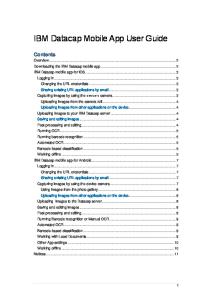
Front panel diagram The following figure illustrates the front panel of the Network Active Bypass unit Your unit's front panel may vary depending on the model:
Note: Segments are arranged right-to-left, in the following order: Segment 4, Segment 3, Segment 2, Segment 1. 1. Network ports: 1G (SR, LR, or Copper) N1 and N2 ports connecting to an Ingress network and Egress network 2. Appliance ports: 1G (SR, LR, or Copper) A1 and A2 ports connecting to an IPS appliance 3. LCD display Note: LCD buttons are not active. 4. LED indicators (position of LED indicators varies depending on the model) v Link/Active LEDs for 1 G ports: lights indicate if a connection exists and the general amount of traffic v Existing connection – Green indicates a connection – Amber indicates a collision – No light indicates no connection v Amount of traffic – Rapid blinking indicates heavy traffic – Slow blinking indicates light traffic – No blinking indicates no traffic 5. Console port serial 6. Management port Ethernet 7. Tap port
Power adapter You must use a UL listed power supply with a rated output of 12 VDC, 5 A, marked LPS or NEC Class 2. Chapter 1. Introducing the Network Active Bypass unit
3
Basic operation This topic describes the basic operating principles of the Network Active Bypass unit.
Typical deployment The following diagram shows how the data is transferred from the network to the Network IPS through the Network Active Bypass unit, and highlights the associated functions handled at each stage of bypass switching.
Switching modes The Network Active Bypass unit provides two switching modes: Switching mode
Description
Active
Active mode channels Ethernet frames between the public network and the private network through the Network IPS appliance. Typically, data flows from the public network to port N1 (network in). The Network Active Bypass unit transfers the data to port A1 (appliance in) and then routes the data through the Network IPS appliance to port A2 (appliance out). Active switching then routes the data through port N2 and out to the private network. Active mode also operates in reverse, routing data from a private network to a public network.
4
Network Active Bypass: User Guide
Switching mode
Description
Bypass
Bypass mode channels Ethernet frames from the public network to port N1 (network in). Data is routed through a closed loop from port N1 (network in) to port N2 (network out) and bypasses the Network IPS appliance so that frames go directly from the public network to the private network. Bypass mode also operates in reverse, routing data from a private network to a public network.
Heartbeat modes The Network Active Bypass unit can continually monitor the health of Network IPS appliances by sending and receiving heartbeat pulses. This ensures real-time safety and accuracy of the data stream. You use a set time defined in the Timeout value (see “Command line parameters” on page 25 for timeout values) to configure heartbeat frames that are sent from the Network Active Bypass unit on one appliance port and received on the other port. Network Active Bypass unit provides the following heartbeat modes : Heartbeat mode
Description
Internal Heartbeat Frame Loopback Mode
A user-defined Ethernet heartbeat frame that is generated by the Network Active Bypass unit. and sent from port A1.The Network Active Bypass unit Ethernet port A2 must receive the same heartbeat frame from the Network IPS appliance. Note: The heartbeat is sent every 100 milliseconds (ms) by default and can be increased up to 25500 ms. This mode is designed for Network IPS appliances that act as a bridge. Make sure appliances are properly configured so that the device does not filter out the heartbeat frame. This mode does not require a driver for Network IPS appliances. Default: 1
Link Status Heartbeat Mode
The heartbeat signal acts as a link status indicator for Network Active Bypass unit Ethernet port A1 and A2. If port A1 or port A2 loses the link, theNetwork Active Bypass unit stops the heartbeat transmissions and activates bypass mode.
Chapter 1. Introducing the Network Active Bypass unit
5
Operation modes The Network Active Bypass unit uses the following operation modes: Operation mode
Description
Mode 0: Normal Active Inline
The bypass unit passes traffic to the Network IPS appliance. If the unit does not receive a heartbeat, then it bypasses the Network IPS appliance and forwards the traffic to the network.
Mode 1: Normal Inline
The bypass unit passes traffic to the network, bypassing the Network IPS appliance. If the unit does not receive a heartbeat, then it passes traffic to the Network IPS appliance.
Mode 2: Manual Active Inline
The bypass unit always passes traffic to the Network IPS appliance, whether it receives a heartbeat or not. Another description for this mode is that the bypass unit always works in Active Switching mode.
Mode 3: Manual Active Bypass
The bypass unit always passes traffic to the network, bypassing the Network IPS appliance, whether it receives a heartbeat or not. Another description for this mode is that the bypass unit always works in Bypass Switching mode. This operation mode is useful for maintenance tasks, such as updating firmware, installing patches, or replacing appliances.
Mode 4: Manual Passive Bypass
The bypass unit does not pass any traffic, either to the Network IPS appliance or to the network. This operation mode is useful for testing high availability scenarios.
6
Network Active Bypass: User Guide
Chapter 2. Setting up the Network Active Bypass unit This chapter contains information you need to connect and configure the Network Active Bypass unit.
Topics “Configuring and deploying the Proventia Network Active Bypass unit”
Configuring and deploying the Proventia Network Active Bypass unit This topic contains detailed steps for configuring and deploying the Network Active Bypass unit.
About this task The following process is required to configure and deploy the Network Active Bypass unit.
Procedure 1. Place the Network Active Bypass unit and the Network IPS appliances on a rack. 2. Connect the cable to and configure the Network IPS appliances using the instructions provided in the Proventia GX Getting Started Guide. 3. Connect the power cables to the Network Active Bypass unit and to two different power sources (for added redundancy). 4. Use a browser to access the management interface and log in. 5. Verify that the Network Active Bypass unit is passing traffic. 6. Use the management interface to set the segment configuration. (This process maps the ports on the appliance and sets bypass tolerances.)
© Copyright IBM Corp. 2009, 2010
7
Placing the Network Active Bypass unit and the Network IPS appliances Procedure 1. Decide where to place the Network Active Bypass unit and the Network IPS appliances. 2. Add the Network Active Bypass unit and the Network IPS appliances to the rack. 3. Connect the cable to the Network IPS appliances using the instructions provided in the Proventia GX Getting Started Guide. Note: The Network Active Bypass unit uses four 1 Gb segments.
Connecting the power cables Procedure 1. Plug the DC connector of each AC adapter into the Network Active Bypass unit. 2. Plug one of the power cables into an AC outlet. Plug the other power cable into an AC outlet serviced by a different AC feed. Tip: Use independent AC power sources to maximize power redundancy in the event of AC power loss from a single source. 3. Check the power LEDs to confirm that the Network Active Bypass unit is receiving power.
Logging into the management interface Procedure 1. Use the management cable (labeled “CAT5E”) to connect a computer to the management port on the Network Active Bypass unit. Important: Make sure you follow industry best practices for securing your critical network infrastructure. Do not connect the management port to any network that is open to external traffic. The management port should be connected only to a restricted network that is dedicated to managing the Network Active Bypass unit and the Network IPS appliances. 2. Start Internet Explorer. 3. Type https://192.168.0.111. Note: The default IP address for the management port is 192.168.0.111. If you change the management port IP address, the Web address to access the management port is changed to include the new IP address. 4. Log in to the management interface. Use the default user name and password the first time you connect to the management interface. Field
Default setting
User Name
admin
Password
admin
Note: If you change the default log on settings on the Users page of the management interface, the values you set are in effect for future log on attempts.
8
Network Active Bypass: User Guide
Setting up e-mail notification About this task Configure e-mail notification to receive a status e-mail when the state of the Network Active Bypass unit changes. You must set up e-mail notification before you configure your segments.
Setting up segments Procedure 1. In the management interface, select theSegment page for the Segment you want to configure. 2. Type or select the appropriate settings, and then click Save
Chapter 2. Setting up the Network Active Bypass unit
9
10
Network Active Bypass: User Guide
Chapter 3. Configuring the Network Active Bypass unit in the management interface You can use either the management interface or the command line interface to set most of the configuration options for the Network Active Bypass unit. This chapter lists the configuration options available through the user interface, and describes how to set them.
Topics “About the management interface” on page 12 “Accessing the management interface” on page 13 “Monitoring the status of the Network Active Bypass unit” on page 14 “Managing settings for the Network Active Bypass unit” on page 15
© Copyright IBM Corp. 2009, 2010
11
About the management interface The Network Active Bypass unit provides a secured Web management interface.
Management pages The management interface consists of a series of pages, as indicated in the following table:
12
Management Page
Description
Status
Status information about the Network Active Bypass unit
Management Port
IP settings for the management port
Segment 1
Port settings and heartbeat settings to activate bypass or get into active mode, for appliances on this segment.
Segment 2
Port settings and heartbeat settings to activate bypass or get into active mode, for appliances on this segment.
Segment 3
Port settings and heartbeat settings to activate bypass or get into active mode, for appliances on this segment.
Segment 4
Port settings and heartbeat settings to activate bypass or get into active mode, for appliances on this segment.
Email Notifications
Settings required for e-mail notification, such as e-mail accounts and mail server information
SNMP Settings
Settings for sending SNMP traps to an SNMP trap server
NTP Settings
Settings that enable the network time protocol (NTP) to synchronize the Network Active Bypass unit time with a network time server
Time Settings
Time zone settings for the Network Active Bypass unit
Backup/Restore
Backup, restore, and reset to factory default functions
Firmware Update
Upload firmware update files to the Network Active Bypass unit
Log Settings
Settings for the system log files
Reboot
Reboot the Network Active Bypass unit
Users
Change the admin password
Remote Authentication
Settings that allow a remote access server to communicate with an authentication server in order to determine if the user has access to the network
Network Active Bypass: User Guide
Accessing the management interface You can manage and monitor the Network Active Bypass unit from any Web browser.
Prerequisite Make sure that the Ethernet management port for the Network Active Bypass unit is connected to the local network or to the host computer.
Default management port IP address and Web address The Network Active Bypass unit has a default IP address assigned to the management port. The default IP address and URL are shown in the following table: Item
Default value
Management port IP address
192.168.0.111
Management port Web address
https://192.168.0.111
These default values remain in effect until you change them. You can use command line parameters or use the Management Port page of the management interface to change the the IP address for the management port. Important: Changes to the management port can interrupt the management interface connection. Make sure that the new IP address is accessible before you make any changes. When you change the IP address, the management port Web address changes also.
Management interface Web address You can access the management interface using a Web address that consists of https:// followed by the management port's IP address. The Web address format is as follows: https://xxx.xxx.xxx.xxx When you type the Web address, replace xxx.xxx.xxx.xxx with the IP address assigned to the management port. For example, the default Web address is https://192.168.0.111 Note: When you enter the Web address, you will see a message regarding the Web site's security certificate. Click “Continue to this website (not recommended)” to proceed.
Logging in When you enter the management Web site, you see the log in screen. Complete the fields as indicated in the following table. Field
Description
User
Type the user name Note: The default user is admin.
Chapter 3. Configuring the Network Active Bypass unit in the management interface
13
Field
Description
Password
Type the password Note: The default password is admin.
The default values remain in effect until you change them. If you need to change the user name or password, you can use the Users page of the management interface or the command line interface.
Monitoring the status of the Network Active Bypass unit This topic provides information about using the management interface to monitor the status of the Network Active Bypass unit.
Checking overall status The Status page is the first page you see when you log in to the management interface. Use the Status page to view information for the Network Active Bypass unit. The Status page provides information in sections, as indicated in the following table. Section
Description
System
Provides general information about the Network Active Bypass unit
Power Supply
Indicates whether power supplies are present or not present
Segment 1
Shows the active/bypass status for segment 1
Segment 2
Shows the active/bypass status for segment 2
Segment 3
Shows the active/bypass status for segment 3
Segment 4
Shows the active/bypass status for segment 4
Tap Settings
Shows current port configurations
Viewing system status The System section provides general system status, as indicated in the following table. Field
Description
Product Name
Displays the name of the Network Active Bypass unit: “Proventia® NAB”
Product ID
Displays the product ID of the Network Active Bypass unit: “Proventia NAB rev 1”
14
Hardware Revision
Displays the hardware version of the Network Active Bypass unit
Firmware Version
Displays the current firmware version of the Network Active Bypass unit
Network Active Bypass: User Guide
Field
Description
Management IP
Displays the IP address for the management port Tip: Use the Management Port page if you want to change IP settings for the management port. Default: 192.168.0.111
Email Notifications
Indicates whether e-mail notifications are enabled or disabled Tip: Use the Email Notification page if you want to change e-mail settings. Default: Disable (Don't send)
Managing settings for the Network Active Bypass unit Use the management interface to view or change settings for the Network Active Bypass unit.
Setting up segment configurations Procedure 1. In the management interface, select the Segment Configuration page. 2. Complete the fields for each of the four segments (A - D) that best fits your specific network environment: Field
Description
Max time allowed between heartbeat acceptance (100 ms - 25500 ms)
Specifies the user-defined Ethernet heartbeat frame generated by the Network Active Bypass unit. The heartbeat frames are sent from the Network Active Bypass unit Ethernet port A1 every 100 milliseconds (ms), and the Network Active Bypass unit Ethernet port A2 must receive the same heartbeat frame from the Network IPS appliance.
Number of HB lost to activate bypass (1–10)
Specifies the heartbeat signal that acts as a link up status indicator for the Network Active Bypass unit Ethernet ports A1 and A2. If port A1 or A2 loses the link, Network Active Bypass unit stops the heartbeat transmission and activates bypass mode.
Number of accepted HB to get into active mode (1–10)
Specifies the user-defined Ethernet heartbeat frame that is generated by the Network IPS appliance. This is the number of heartbeats the Network Active Bypass unit must receive in order for the unit to change from bypass to active. Default: 1
Chapter 3. Configuring the Network Active Bypass unit in the management interface
15
Field
Description
Operation Mode
Specifies the operation mode of the Network Active Bypass unit: v Mode 0: Normal Active Bypass (Default mode) - If Network Active Bypass unit receives heartbeat signals within the Timeout period, the switching mode remains or is changed to Active Switching mode. If Network Active Bypass unit does not receive heartbeat signals within the Timeout period, it will change to or remain in Bypass Switching mode. By default (without a heartbeat), Network Active Bypass unit remains in Bypass Switching mode. v Mode 1: Normal Active Inline - If Network Active Bypass unit receives heartbeat signals within the Timeout period, the switching mode remains or is changed to Bypass Switching mode. If Network Active Bypass unit does not receive heartbeat signals within the Timeout period, it will change to or remain in Active Switching mode. By default (without a heartbeat), Network Active Bypass unit remains in Active Switching mode. v Mode 2: Manual Active - Network Active Bypass unit is always in Active Switching mode. v Mode 3: Manual Active Bypass - Network Active Bypass unit is always in Bypass Switching mode. v Mode 4: Manual Passive Bypass Network Active Bypass unit is in passive bypass, in which the optical switch is “Close” in bypass mode.
Link fault detection
Generates an SNMP trap if a network port stops functioning: v 0: disables the system from detecting Link Fault Detection v 1: enables the system to detect and activate Link Fault Detection Default: Enabled
16
Network Active Bypass: User Guide
Field
Description
Tap Setting
Specifies the ports on the Network Active Bypass unit for data flow during Bypass Switching mode and Active Switching mode: v Port N1: Network in v Port N2: Network out v Port A1: Appliance in v Port A2: Appliance out Options for Tap setting are: v RX v TX v RX/TX
Configuring Management Port settings Procedure Use the Management Port page to configure IP settings for the management port. Field
Description
IP Address
IP address of the management port Default: 192.168.0.111
Network Mask
IP address of the network or subnet mask Default: 255.255.255.0
Gateway
IP address of the network gateway Default: 192.168.0.1
DNS 1
IP address of the primary domain name system server Default: 192.168.0.1
DNS 2
IP address of the secondary domain name system server Default: 0.0.0.0
Chapter 3. Configuring the Network Active Bypass unit in the management interface
17
Setting up e-mail notifications About this task TheNetwork Active Bypass unit provides an e-mail notification function that you can configure to send an e-mail message when the switching mode of a segment has changed. Use the Email Notification page to configure e-mail servers and accounts, and to enable or disable notifications.
Procedure Set the values as indicated in the following table. Field
Description
Email Notification
Enable or disable e-mail notification Default: Disabled (Don't send)
Outgoing Mail Server (SMTP)
Address of the appropriate outgoing SMTP mail server
Outgoing Mail Server (SMTP) Port
Port number of the outgoing SMTP mail server Default: 25
SMTP Username
User name for the outgoing SMTP mail server
SMTP Password
Password for the outgoing SMTP mail server (if applicable)
Outgoing Server (SMTP) Security
SSL encryption used between the SMTP mail server and mail client Default: Enable (Secured)
From (Sender's email address)
Name or address that should be displayed in the From field of an outgoing e-mail message
To (List of recipients, comma separated)
List of e-mail addresses to whom the notification should be sent
Subject
Subject to be displayed in the subject line of the outgoing e-mail message Example: “Proventia NAB status report”
18
Network Active Bypass: User Guide
Configuring SNMP traps About this task The Network Active Bypass unit provides an SNMP trap function that can send messages to a trap server when the segment status or power supply status changes. Use the SNMP Settings page to configure the SNMP destination IP and SNMPv2 community name, and to enable or disable the SNMP trap function.
Procedure Complete the fields as indicated in the following table. Field
Description
Send SNMP Traps
Enable or disable the sending of SNMP traps Default: Disabled
SNMP traps destination IP
Destination IP of the SNMP trap server Default: localhost
SNMPv2 community
Community name of the SNMP trap server Default: public
Synchronizing time and setting time zones Procedure Use the NTP Setting page to enable the network time protocol (NTP) to synchronize the Network Active Bypass unit time with a network time server. Use the Time Setting page to set the time zone for the Network Active Bypass unit. Set the values as described in the following table. Field
Description
NTP
Protocol that synchronizes the Network Active Bypass unit time with a network time server Default: Disabled
NTP Server
Public domain of a collection of computers that provide time using NTP
Time Zone
Time zone used by the Network Active Bypass unit Default: America\New York
Chapter 3. Configuring the Network Active Bypass unit in the management interface
19
Managing User Account settings Procedure Use the Users page to change the user name and password required to access the Web management interface. Field
Description
Password
Password required to access the management interface from a Web browser
Confirm Password
Confirmation for the password required to access the management interface from a Web browser
Backing up or restoring settings Procedure Use the Backup/Restore page to make a backup file or to return the Network Active Bypass unit to its default settings. Complete the fields as indicated in the following table.
20
Field
Description
Backup
Saves a copy of current settings on the Network Active Bypass unit in a file named config.txt
Restore From
Location of a stored backup file. Type the file location or navigate to the file, and click Restore From.
Restore to Factory Default Configuration
Restores the Network Active Bypass unit to the default configuration and then restarts it Important: The IP address for the management interface is not reset.
Network Active Bypass: User Guide
Applying firmware updates About this task Use the Firmware Update page to manually upload firmware updates to theNetwork Active Bypass unit. Browse to the update file location, and click Upload Firmware. Note: It can take up to 5 minutes for the process to finish. Check the Status page to verify that the new firmware version has been installed.
Enabling system logging About this task Use the Log Setting page to enable the consolidation of log data from various systems into a central repository. System logs contain important information about actions the Network Active Bypass unit has taken, due to user interaction, such as a system restart or manual feature configuration, or due to a system action, such as an automatic restart after firmware update.
Procedure Complete the fields as indicated in the following table. Field
Description
Logging
Set up consolidation of log data Default: Disabled
Syslog Server Host
IP address of the central repository of log data Default: localhost
Syslog Server Port
Port number on which the syslog server is monitoring Default: 514
Syslog Server Identification
Host name of the syslog server Default: NAB
Chapter 3. Configuring the Network Active Bypass unit in the management interface
21
Restarting the Network Active Bypass unit About this task Use the Restart page to restart the Network Active Bypass unit.
Configuring Remote Authentication About this task Use the Remote Authentication page to configure settings for the TACACS+ protocol. The TACACS+ (Terminal Access Controller Access Control System Plus) protocol provides access control (separate authentication, authorization, and accounting services) for Network Active Bypass unit from one or more servers.
Procedure Complete the fields as indicated in the following table. Field
Description
TACACS+
Allows TACACS+ protocol for access control Default: Disabled
Server
IP address of the server providing access services Default: 0.0.0.0
Encrypt
Encrypts the body of the TACACS+ packets for more secure communications Default: No
Secret
Shared secret value for encryption that is known to both the client and the daemon Default: None
Service
Services that are requesting authentication Default: All
22
Network Active Bypass: User Guide
Chapter 4. Configuring the Network Active Bypass unit using the command line interface You can use either the management interface or the command line interface to set most of the configuration options for the Network Active Bypass unit. This chapter lists the command line parameters, and describes how to set up configuration options through the command line interface.
Topics “Accessing the command line interface” on page 24 “Syntax for command line parameters” on page 25 “Command line parameters” on page 25
© Copyright IBM Corp. 2009, 2010
23
Accessing the command line interface This topic contains the information you need to access the command line interface.
Connection types You can access the command line interface for the Network Active Bypass unit in one of two ways: v Through a serial terminal emulator v Through an SSH remote shell emulator
Connection requirements The requirements for both connection types are shown in the following table. Connection type
Port on Network Active Bypass unit
Cable
Serial terminal emulator
Console port
Console cable
SSH remote shell emulator
Management port
Management cable
Serial terminal settings Use a serial terminal emulator and the following terminal settings: Setting
Value
Communications Port
Typically COM1 (depending on computer setup)
Emulation
VT100
Bits per second
115,200
Data bits
8
Parity
None
Stop
1
Flow Control
None
SSH port The Network Active Bypass unit SSH server uses the standard port 22.
User name and password Use the administrator account to configure parameters and to monitor the status of the Network Active Bypass unit. The default user name and password are listed in the following table.
24
Field
Description
User
Type the user name Note: The default user is admin.
Password
Type the password Note: The default user is admin.
Network Active Bypass: User Guide
Note: You can change the password through the command line interface or through the management interface.
Syntax for command line parameters This topic outlines the syntax required to set or to retrieve values using the command line parameters.
Permissions required Only the Admin account has permissions to set and to retrieve system parameters.
Command line syntax Use the following command line syntax to set or to retrieve values for parameters. Command
Action
cli get |more
Outputs values for all parameters
cli get parameter_ name
Specifies a value for the parameter Example: Typing cli get timeout displays the timeout value in decimal form
cli set parameter_name parameter_value
Sets a value for the parameter you specify Example: Typing cli set timeout 20 sets the timeout value to 20
Command line parameters This topic lists the command line parameters available for the Network Active Bypass unit. The parameters are divided into the following categories: v Management port v Communication v E-mail notification v SNMP v Operational
Use parameters with care Use these command line parameters carefully, because they control the behavior of the Network Active Bypass unit. Do not change a default value unless you are sure of the effect the change will have on your network. Some parameters should not be changed unless you are instructed to do so by a representative from IBM ISS Customer Support.
Management port parameters The parameters in the following table control the IP settings for the management port.
Chapter 4. Configuring the Network Active Bypass unit using the command line interface
25
Parameter
Description
ip
Current IP address for the management port for Network Active Bypass unit Default: 172.16.124.17
mask
Subnet mask for the management port Default: 255.255.255.0
gw
Gateway IP address for the management port Default: 172.16.124.1
current_ip
Current IP address for the management port Note: The current_ip parameter is read only.
Communication parameters The parameters in the following table control the communication features of the Network Active Bypass unit. Use cli get to retrieve the current value for a parameter. Use cli set, plus the new value to change the value of the parameter. For example, cli set ip 127.0.0.1. Parameter
Description
dns
DNS server IP address Note: This parameter corresponds to DNS 1 in the user interface.
dns2
Second DNS server IP address
domain
Domain name for the local host Default: local
dhcp
DHCP client dhcp: Set this parameter to dhcp to enable the DHCP client on the Network Active Bypass unit management port. Static: Set this parameter to static to disable the DHCP client on the Network Active Bypass unit management port
host
Host name for the unit This parameter is read-only. Default: Proventia_NAB
username
Administrator account name Default: admin
password
Administrator password Default: admin
26
Network Active Bypass: User Guide
Parameter https
Description Enables or disables the HTTPS server v 0: disables the secure Web management interface v 1: enables access to the secure Web management interface Default: 1 (enabled)
E-mail notification parameters The parameters in the following table control the e-mail notification feature. Parameter
Description
email
Enables or disables the e-mail notification feature v 0: disables e-mail notification v 1: enables e-mail notification Default: 1
email_from
Name or e-mail address that is displayed in the "From" field on the e-mail notification
email_security
Enables or disables the e-mail security feature v 0: disables e-mail security feature v 1: enables e-mail security feature Default: 1
email_username
User name for the e-mail account used to send e-mail notifications from the Network Active Bypass unit
email_password
Password for the e-mail account used to send e-mail notifications from the Network Active Bypass unit
email_server
SMTP server address for the mail server
email_subject
Text to be displayed in the subject line of notification e-mail messages Sample: "Notice: PNAB segment(s) have switched modes"
email_to
List of e-mail addresses to which the notification should be sent
SNMP parameters The parameters in the following table control the sending of SNMP traps. Parameter
Description
snmp
Enables or disables the SNMP function v 0: disables SNMP function v 1: enables SNMP function Default: 0 (disabled) Chapter 4. Configuring the Network Active Bypass unit using the command line interface
27
Parameter
Description
snmp_community
SNMP community name Default: public
snmp_destination
SNMP destination Default: localhost
LFD
Link Fault Detection generated if a network port goes down v 0: disables the system from detecting Link Fault Detection v 1: enables the system to detect and activate Link Fault Detection Default: Enabled
Operational parameters The parameters in the following table control the behavior of the Network Active Bypass unit. Parameter
Description
timeout
Timeout value for Network Active Bypass unit Each timeout unit is 100 ms. (Timeout range is 100 milliseconds to 25.5 seconds.) In default bypass operation mode, if the Network Active Bypass unit does not detect a heartbeat frame within the set timeout value, the segment will switch from active to bypass. Default: 1
force
Force (debug) mode for each I/O unit v 0: Disables force (debug) mode v 2: Forces segment to Active Switch mode v 4: Forces segment to Bypass Switch mode Default: 0 (Disable)
op_mode
Default operation mode for the Network Active Bypass unit v 0: Normal Active Bypass If heartbeat is received, system will be inline. v 1: Normal Inline If heartbeat is received, system will be in bypass. v 2: Always Inline v 4: Always Active Bypass v 5: Manual Passive Bypass (Bypass Switch is closed in bypass mode) Default: 0 (Normal Active Bypass)
28
Network Active Bypass: User Guide
Parameter
Description
hb_mode
Heartbeat mode for the Network Active Bypass unit v hb_mode 1: system is generating heartbeat v hb_mode 2: external source is generating heartbeat v hb_mode 3: system activates bypass depending on link detection on the appliance Default: hb_mode 1
state
State of the Network Active Bypass unit This parameter is read-only. v 0: Bypass Switch state v 1: Active/Inline Switch state
active_hb_cnt
Stores the active heartbeat signal count The segment switches to Active Switch mode only if it receives active_hb_cnt number for a consecutive heartbeat. Default: 2 (Range: 1 - 10)
bypass_hb_cnt
Stores the bypass heartbeat signal count The segment will switch to Bypass Switch mode only if it loses bypass_hb_cnt heartbeat signal number. Default: 3 (Range: 1 - 10)
TACACS+ parameters Use the following parameters to configure TACACS+ from the CLI: Parameter
Description
tacacs
Values: v 0: disabled v 1: enabled
tacacs_encryption
Values: v 0: disabled v 1: enabled
tacacs_protocol
TACACS+ protocol Default: all
tacacs_secret
TACACS+ secret Default: None
tacacs_server
IP number of TACACS+ server
tacacs_service
TACACS+ service Default: all
Chapter 4. Configuring the Network Active Bypass unit using the command line interface
29
30
Network Active Bypass: User Guide
Notices This information was developed for products and services offered in the U.S.A. IBM may not offer the products, services, or features discussed in this document in other countries. Consult your local IBM representative for information on the products and services currently available in your area. Any reference to an IBM product, program, or service is not intended to state or imply that only that IBM product, program, or service may be used. Any functionally equivalent product, program, or service that does not infringe any IBM intellectual property right may be used instead. However, it is the user's responsibility to evaluate and verify the operation of any non-IBM product, program, or service. IBM may have patents or pending patent applications covering subject matter described in this document. The furnishing of this document does not grant you any license to these patents. You can send license inquiries, in writing, to: IBM Director of Licensing IBM Corporation North Castle Drive Armonk, NY 10504-1785 U.S.A. For license inquiries regarding double-byte (DBCS) information, contact the IBM Intellectual Property Department in your country or send inquiries, in writing, to: Intellectual Property Licensing Legal and Intellectual Property Law IBM Japan Ltd. 1623-14, Shimotsuruma, Yamato-shi Kanagawa 242-8502 Japan The following paragraph does not apply to the United Kingdom or any other country where such provisions are inconsistent with local law: INTERNATIONAL BUSINESS MACHINES CORPORATION PROVIDES THIS PUBLICATION "AS IS" WITHOUT WARRANTY OF ANY KIND, EITHER EXPRESS OR IMPLIED, INCLUDING, BUT NOT LIMITED TO, THE IMPLIED WARRANTIES OF NON-INFRINGEMENT, MERCHANTABILITY OR FITNESS FOR A PARTICULAR PURPOSE. Some states do not allow disclaimer of express or implied warranties in certain transactions, therefore, this statement may not apply to you. This information could include technical inaccuracies or typographical errors. Changes are periodically made to the information herein; these changes will be incorporated in new editions of the publication. IBM may make improvements and/or changes in the product(s) and/or the program(s) described in this publication at any time without notice. Any references in this information to non-IBM Web sites are provided for convenience only and do not in any manner serve as an endorsement of those Web sites. The materials at those Web sites are not part of the materials for this IBM product and use of those Web sites is at your own risk.
© Copyright IBM Corp. 2009, 2010
31
IBM may use or distribute any of the information you supply in any way it believes appropriate without incurring any obligation to you. Licensees of this program who wish to have information about it for the purpose of enabling: (i) the exchange of information between independently created programs and other programs (including this one) and (ii) the mutual use of the information which has been exchanged, should contact: IBM Corporation Project Management C55A/74KB 6303 Barfield Rd., Atlanta, GA 30328 U.S.A Such information may be available, subject to appropriate terms and conditions, including in some cases, payment of a fee. The licensed program described in this document and all licensed material available for it are provided by IBM under terms of the IBM Customer Agreement, IBM International Program License Agreement or any equivalent agreement between us. All statements regarding IBM's future direction or intent are subject to change or withdrawal without notice, and represent goals and objectives only.
Trademarks IBM, the IBM logo, and ibm.com are trademarks or registered trademarks of International Business Machines Corp., registered in many jurisdictions worldwide. Other product and service names might be trademarks of IBM or other companies. A current list of IBM trademarks is available on the Web at “Copyright and trademark information” at Copyright and trademark information at www.ibm.com/legal/copytrade.shtml. Linux is a registered trademark of Linus Torvalds in the United States, other countries, or both. UNIX is a registered trademark of The Open Group in the United States and other countries. Microsoft and Windows are trademarks of Microsoft Corporation in the United States, other countries, or both. Other company, product, or service names may be trademarks or service marks of others.
32
Network Active Bypass: User Guide
Index B backup/restore
syslog 21 system status
20
14
T
C command line interface accessing 24 parameters 25 command line syntax 25
D documentation
vii
E e-mail notification
18
TACACS See Terminal Access Controller Access Control System TACACS+ See Terminal Access Controller Access Control System Plus technical support web site viii technical support, IBM Security Solutions viii Terminal Access Controller Access Control System 22 Terminal Access Controller Access Control System+ 22
U
F firmware update
updating firmware 21 user account settings 20 user interface 11
21
I IBM Internet Security Solutions Security Solutions technical support viii IBM Security Solutions technical support viii
L license agreement
viii
M management interface 11 management port settings 17
P package contents v power fail protection power supply 3
2
R reboot
22
S segment configuration 15 SSH port 24 status 14 switching modes 4 syntax, command line 25 © Copyright IBM Corp. 2009, 2010
33
34
Network Active Bypass: User Guide
����
Printed in USA