Proc. Tokai Univ., Ser. E Proc.Schl. Schl.Eng. Eng. Tokai Univ., Ser. E 40 (2015) 63-70 (2015)■-■
Four-Wheel Drive and Independent Steering for Small Electric Vehicles: Active Stability Control during High–Speed Cornering By Muhammad Izhar ISHAK *1 , Hirohiko OGINO *2 and Yoshio YAMAMOTO *3 (Received on Mar. 30, 2015 and accepted on Jul. 30, 2015)
Abstract Since car manufacturers pursue in the development of environmental -friendly vehicle, the demand for extensive research on stability, controllability, and reliability of electric vehicles (EVs) increases. Electric powered and by-wire control technology allow manufacturers to build independent four -wheel steering of an allwheel drive in-wheel EV. In past research, we investigated the advantages of a four-wheel drive and independent steering system (4WDIS) of an in-wheel small EV in comparison with a two-wheel steering (2WS) vehicle. During low-speed cornering, a 4WDIS in-wheel small EV is capable of cornering with a short radius and has a higher response to driver’s steering with the assistance of passive-control rear-wheel steering. This paper describes an active stability control of a 4WDIS in-wheel small EV during high-speed cornering using a numerical simulation. In the simulation, a 4WDIS in-wheel small EV is designed with a nonlinear model. Therefore, a feedback control cannot be implemented directly because the yaw rotational speed couples with the velocity as expressed in the dynamic equation of motion. Hence, we propose controlling the input of a state observer with a controlled linear model enabling the output to be fed forward to the vehicle. A Linear Quadratic Regulator is used to establish an optimal control for the linear model. Based on the result, a slight deviation is observed between the output of the state observer and vehicle model when using the feed-forward control method. As a solution, these output error between both models is calculated and multiplied by a high gain, then fed back into the linear model before the control input is fed forward to the vehicle . Finally, we compare the feed-forward control system with the feedback control system of the vehicle. The results show that our vehicle’s active stability control is able to achieve a steady-state cornering at high-speed. . Keywords: Four–wheel drive, Independent–steering system, In-wheel small EV, State observer, Linear quadratic regulator potential in the future of EVs for its compactness and high
1. Introduction
energy efficiency1-4) . In past research, results show that the inIn recent years, electric vehicles (EVs) have renewed the
wheel motor system offers more freedom of movement for
common interest of consumers and manufacturers as they are
each wheel and can be governed separately by control systems
seen to bring solutions to the environmental concerns over
such as the anti-lock brake system (ABS) and the traction
petroleum-based transportation and the issue of fossil fuel
control system (TCS) 5) . As the automotive industry progresses in electric-based
depletion around the world. Small EVs for transportation are especially useful in urban areas where spaces are limited. The
transportation,
driving mechanisms of an EV can be divided into two types.
controllability, and reliability of EVs. Some of the mechanical
demand
increases
for
better
stability,
The most basic type is the central motor system, where a
parts of a conventional vehicle will be converted into electric
conventional combustion engine is replaced with an electric
modules that only require signal cables. By combining
motor. The other type is the in-wheel motor system, where a
electric-powered and by-wire control technology, an extensive
driving motor is located near the hub of each wheel. We
amount of mechanical parts can be eliminated, enabling then
believe that the in-wheel motor system has tremendous
a freedom of layouts and driving potentials. For this reason,
*1 *1 *2 *2 *3 *3
an independent four-wheel steering system for EVs becomes
Graduate Student, Course Course of of Science Science and and Technology Technology Graduate Student, Professor, Department of of Prime Prime Mover Mover Engineering Engineering Professor, Department Professor, Department of of Precision Professor, Department Precision Engineering Engineering
Vol.Ⅹ XXXI, Vol. ⅩⅩⅩ, 2015 2015
much easier to be implemented compared with conventional ―1―
− 63 −
Four-Wheel Drive and Independent Steering for Small Electric Vehicle: Active Stability Control during High Speed Cornering Muhammad Izhar ISHAK, Hirohiko OGINO and Yoshio YAMAMOTO each tire, W z: wheels load subject to load transfer, β, β*: side-
vehicles. Vehicles are inherently nonlinear systems and they tend to
slip angle of vehicle and state observer, β FR, β FL, βRR, βRL: tire
under-steer at low-speed and over-steer (OS) at high-speed. In
side-slip angle, µ: friction coefficient, θ F, θR :front and rear tire
the past, we investigated the steering performance of a 4WDIS
steer angle, γ, γ*: yaw rotational speed of vehicle and state
in-wheel small EV (Toyota COMS as model) under low-speed
observer, ρ: slip ratio, ω : tire rotational speed.
driving using numerical simulations
6) .
The vehicle model
produced an OS gradient, which was found to depend on tire-
3. Vehicle Dynamics
cornering stiffness and length to the center of gravity of the vehicle. With a vehicle in OS, the circular turning radius for a
3.1 Nonlinear model
given steering angle vanishes and the yaw angular velocity and
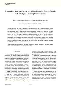
A Toyota COMS EV (Fig. 1) is used as a test model in the
the side-slip angle rapidly increases. The purpose of the study
simulation. Although the vehicle is a 2WD in-wheel EV and
was to increase the mobility of a small EV. A passive control
has only front-wheel steering, it is configured in simulations
system governs the rear steering. At a low speed, the vehicle
with a four-wheel drive and independent steering system.
has a high traction with the road surface and maintains stability,
A general vehicle model has six degrees of freedom: three
and hence a passive control is considered adequate. As a result,
translational along the x, y, and z-axes, and three rotational
a 4WDIS in-wheel EV is capable of cornering with a shorter
about the x, y and z-axes. In this study, however, a planar
cornering radius and has a higher response to the driver’s
motion is assumed so that a translation along the z-axis and
steering.
rotations about the x and y-axes are disregarded. Fig. 2 depicts
In this paper, we investigate the active stability control of
the force vector used to construct the dynamic equations of
a 4WDIS in-wheel small EV under high-speed cornering by
motion for the vehicle and for the yaw rotational speed 7) .
using numerical simulations. In the simulation, a nonlinear
The assumption made necessitates us to calculate the
model is employed for the EV. As yaw rotational speed and
dynamic equations for longitude and latitude velocities,
velocity are coupled, any feedback control (FBC) is
including the coupling of the yaw rotation speed with the
incompatible with the nonlinear model. First, it is examined
velocities.
whether the control input of a state observer with a controlled linear model can be fed forward to the non-linear vehicle model. Cornering power for the linear model is achieved by linearizing the side-slip angle verses cornering force for the nonlinear model. A linear quadratic regulator is used to establish an optimal control in the linear model. The output error between the state observer and the vehicle model is calculated and multiplied with a high gain, which is then fed back into the linear model before the control input is fed forward to the vehicle model. The feed-forward control (FFC) system is then compared with the FBC system for the 4WDIS
Fig. 1 Toyota COMS EV as a vehicle model
in-wheel small EV. A 4WDIS in-wheel small EV with an active stability can achieve a steady-state cornering at high speed. 2. Nomenclature b: width of tire-interaction surface = 0.1 m , d F: front tread = 0.84 m , d R : rear tread = 0.815 m , I: yaw inertia moment at the center of gravity of the vehicle = 1470 kgm2 , Kx, Ky : tire stiffness = 3.33x10 6 N/m3 , KF, KR : front and rear tire cornering power, l: length of tire interaction surface = 0.15 m , lF: length from front axle to the center of gravity of the vehicle = 0.64 m , lR : length from rear axle to the center of gravity of vehicle = 0.64 m , m: mass of the vehicle = 421.61 kg , u: longitude velocity, v: lateral velocity, X FR, XFL, XRR, XRL, :
Fig. 2 Vehicle force vectors in four-wheel steering
friction force for each tire, Y FR, Y FL, Y RR, YRL, : lateral force for ―2―
− 64 −
Proceedings Proceedingsofofthe theSchool School of Engineering Engineering, Tokai TokaiUniversity, University, Series Series E
Muhammad Izhar ISHAK, Hirohiko OGINO and Yoshio YAMAMOTO
Four-Wheel Drive and Independent Steering for Small Electric Vehicles: Active Stability Control during High–Speed Cornering 𝑣𝑣 + 𝑙𝑙𝐹𝐹 𝛾𝛾 𝛽𝛽𝐹𝐹𝐹𝐹 = tan−1 ( ) − 𝜃𝜃𝐹𝐹 𝑢𝑢 + 𝑑𝑑𝐹𝐹 𝛾𝛾 ⁄2
𝑑𝑑𝑑𝑑 m ( − 𝑣𝑣𝑣𝑣) = (𝑋𝑋𝐹𝐹𝐹𝐹 + 𝑋𝑋𝐹𝐹𝐹𝐹 ) cos 𝜃𝜃𝐹𝐹 𝑑𝑑𝑑𝑑
+ (𝑋𝑋𝑅𝑅𝑅𝑅 + 𝑋𝑋𝑅𝑅𝑅𝑅 ) cos 𝜃𝜃𝑅𝑅 − (𝑌𝑌𝐹𝐹𝐹𝐹 + 𝑌𝑌𝐹𝐹𝐹𝐹 ) sin 𝜃𝜃𝐹𝐹
𝑣𝑣 + 𝑙𝑙𝐹𝐹 𝛾𝛾 𝛽𝛽𝐹𝐹𝐹𝐹 = tan−1 ( ) − 𝜃𝜃𝐹𝐹 𝑢𝑢 − 𝑑𝑑𝐹𝐹 𝛾𝛾 ⁄2
(1)
− (𝑌𝑌𝑅𝑅𝑅𝑅 + 𝑌𝑌𝑅𝑅𝑅𝑅 ) sin 𝜃𝜃𝑅𝑅
𝑣𝑣 − 𝑙𝑙𝑅𝑅 𝛾𝛾 𝛽𝛽𝑅𝑅𝑅𝑅 = tan−1 ( ) − 𝜃𝜃𝑅𝑅 𝑢𝑢 + 𝑑𝑑𝑅𝑅 𝛾𝛾⁄2
𝑑𝑑𝑑𝑑 m ( + 𝑢𝑢𝑢𝑢) = (𝑋𝑋𝐹𝐹𝐹𝐹 + 𝑋𝑋𝐹𝐹𝐹𝐹 ) sin 𝜃𝜃𝐹𝐹 𝑑𝑑𝑑𝑑
+ (𝑋𝑋𝑅𝑅𝑅𝑅 + 𝑋𝑋𝑅𝑅𝑅𝑅 ) sin 𝜃𝜃𝑅𝑅 + (𝑌𝑌𝐹𝐹𝐹𝐹 + 𝑌𝑌𝐹𝐹𝐹𝐹 ) cos 𝜃𝜃𝐹𝐹
I
𝑣𝑣 − 𝑙𝑙𝑅𝑅 𝛾𝛾 𝛽𝛽𝑅𝑅𝑅𝑅 = tan−1 ( ) − 𝜃𝜃𝑅𝑅 𝑢𝑢 − 𝑑𝑑𝑅𝑅 𝛾𝛾⁄2
The slip ratio ρ can be represented in terms of the traction
(2)
+ (𝑌𝑌𝑅𝑅𝑅𝑅 + 𝑌𝑌𝑅𝑅𝑅𝑅 ) cos 𝜃𝜃𝑅𝑅
between the road and the tire surface, which is defined as
𝑑𝑑𝑑𝑑 = 𝑙𝑙𝐹𝐹 [(𝑋𝑋𝐹𝐹𝐹𝐹 + 𝑋𝑋𝐹𝐹𝐹𝐹 ) sin 𝜃𝜃𝐹𝐹 + (𝑌𝑌𝐹𝐹𝐹𝐹 + 𝑌𝑌𝐹𝐹𝐹𝐹 ) cos 𝜃𝜃𝐹𝐹 ] 𝑑𝑑𝑑𝑑 +𝑙𝑙𝑅𝑅 [(𝑋𝑋𝑅𝑅𝑅𝑅 + 𝑋𝑋𝑅𝑅𝑅𝑅 ) sin 𝜃𝜃𝑅𝑅 + (𝑌𝑌𝑅𝑅𝑅𝑅 + 𝑌𝑌𝑅𝑅𝑅𝑅 ) cos 𝜃𝜃𝑅𝑅 ] +
+
𝑑𝑑𝐹𝐹 [(𝑋𝑋𝐹𝐹𝐹𝐹 + 𝑋𝑋𝐹𝐹𝐹𝐹 ) cos 𝜃𝜃𝐹𝐹 + (𝑌𝑌𝐹𝐹𝐹𝐹 + 𝑌𝑌𝐹𝐹𝐹𝐹 ) sin 𝜃𝜃𝐹𝐹 ] 2
𝑑𝑑𝑅𝑅 [(𝑋𝑋𝑅𝑅𝑅𝑅 + 𝑋𝑋𝑅𝑅𝑅𝑅 ) cos 𝜃𝜃𝑅𝑅 + (𝑌𝑌𝑅𝑅𝑅𝑅 + 𝑌𝑌𝑅𝑅𝑅𝑅 ) sin 𝜃𝜃𝑅𝑅 ] 2
𝜌𝜌 =
𝑟𝑟𝑟𝑟 − 𝑢𝑢 𝑟𝑟𝑟𝑟
following equation (3)
{
depend on the slip ratio, tire side-slip angle, and weight
𝑘𝑘 = 1.0 (𝑑𝑑𝑑𝑑𝑑𝑑 𝑎𝑎𝑎𝑎𝑎𝑎ℎ𝑎𝑎𝑎𝑎𝑎𝑎) 𝑘𝑘 = 0.2 (𝑖𝑖𝑖𝑖𝑖𝑖 𝑟𝑟𝑟𝑟𝑟𝑟𝑟𝑟)
4. State Observer Unit
is also used to derive the following equations 8) , λ = √𝜌𝜌2 + (
𝑏𝑏𝑙𝑙 𝑇𝑇 2 𝑏𝑏𝑙𝑙 𝑇𝑇 2 𝐾𝐾𝑥𝑥 , 𝐾𝐾𝛽𝛽 = 𝐾𝐾 𝐾𝐾𝜌𝜌 = 2 2 𝑦𝑦
4.1 Linear model The state observer unit uses linear model dynamic
2
𝐾𝐾𝛽𝛽 ) tan2 𝛽𝛽 𝐾𝐾𝜌𝜌
equations of the translational motion and yaw rotational motion such as, 𝑑𝑑𝑑𝑑 m𝑣𝑣 ( + 𝛾𝛾) = 2𝑌𝑌𝑓𝑓 + 2𝑌𝑌𝑟𝑟 + 𝐺𝐺 𝑑𝑑𝑑𝑑 I
If 𝜉𝜉𝜌𝜌 ≥ 0,
𝜌𝜌 1 1 1 𝑋𝑋 = −𝐾𝐾𝜌𝜌 𝜌𝜌𝜉𝜉𝑝𝑝 2 − 6𝜇𝜇𝑊𝑊𝑧𝑧 ( − 𝜉𝜉𝑝𝑝 2 + 𝜉𝜉𝑝𝑝 3 ) 𝜆𝜆 6 2 3 𝑌𝑌 = −𝐾𝐾𝛽𝛽 (1 + 𝜌𝜌) tan 𝛽𝛽 𝜉𝜉𝑝𝑝
2
𝐾𝐾𝛽𝛽 tan 𝛽𝛽(1 + 𝜌𝜌) −6𝜇𝜇𝑊𝑊𝑧𝑧 ( ) 𝐾𝐾𝜌𝜌 𝜆𝜆
else, 𝜌𝜌 𝑋𝑋 = −𝜇𝜇𝑊𝑊𝑧𝑧 𝜆𝜆
𝑑𝑑𝑑𝑑 = (2𝑙𝑙𝑓𝑓 𝑌𝑌𝑓𝑓 − 2𝑙𝑙𝑟𝑟 𝑌𝑌𝑟𝑟 − 𝑙𝑙𝐺𝐺 𝐺𝐺) cos 𝛽𝛽 𝑑𝑑𝑑𝑑
(9) (10)
It is to be noted that there is no difference in the characteristics of the left and right tires due to linearity, hence, a 2-wheel model is derived from the equations. If the side-slip angle is
(4)
small, it is assumed that the direction perpendicular to the traveling direction of the vehicle almost coincides with the
1 1 1 × ( − 𝜉𝜉𝑝𝑝 2 + 𝜉𝜉𝑝𝑝 3 ) 6 2 3
𝐾𝐾𝛽𝛽 tan 𝛽𝛽(1 + 𝜌𝜌) 𝑌𝑌 = −𝜇𝜇𝑊𝑊𝑧𝑧 ( ) 𝐾𝐾𝜌𝜌 𝜆𝜆
(8)
where
distribution. The model’s deformation of the tire tread rubber
,
10) .
μ = −1.10k × (𝑒𝑒 35𝜌𝜌 − 𝑒𝑒 0.35𝜌𝜌 )
model. Thus, the equations for friction and lateral forces
𝐾𝐾𝜌𝜌 𝜆𝜆 3𝜇𝜇𝑊𝑊𝑧𝑧 (1 − 𝜌𝜌)
(7)
Then the coefficient of friction µ can be approximated by the
3.2 Nonlinear tire characteristics In the simulation, we model the wheels using a brush tire
𝜉𝜉𝑝𝑝 = 1 −
(6)
lateral direction y. Therefore, no coupling exists between the yaw rotational speed and the vehicle’s translational velocity. 4.2 Linear tire characteristics The linear lateral force is defined by (5)
𝑌𝑌𝑓𝑓 = −𝐾𝐾𝑓𝑓 𝛽𝛽𝑓𝑓 = −𝐾𝐾𝑓𝑓 (𝛽𝛽 + 𝑌𝑌𝑟𝑟 = −𝐾𝐾𝑟𝑟 𝛽𝛽𝑟𝑟 = −𝐾𝐾𝑟𝑟 (𝛽𝛽 −
The equation for side-slip angle for each tire is given as follows 9) .
𝑙𝑙𝑓𝑓 𝛾𝛾 − 𝜃𝜃𝑓𝑓 ) 𝑣𝑣
𝑙𝑙𝑟𝑟 𝛾𝛾 − 𝜃𝜃𝑟𝑟 ) 𝑣𝑣
(11) (12)
Here, the cornering power of the front and rear wheels, K F and KR , are obtained from the tangent at the origin for the plot of side-slip angle verses cornering force in the nonlinear vehicle
Vol.Ⅹ XXXI, Vol. ⅩⅩⅩ, 2015 2015
―3―
− 65 −
Four-Wheel Drive and Independent Steering for Small Electric Vehicle: Active Stability Control during High Speed Cornering Muhammad Izhar ISHAK, Hirohiko OGINO and Yoshio YAMAMOTO model. In contrast, with the tire characteristics of the nonlinear
in which q 11, q 22, and w are appropriately chosen constant
model, the actual vehicle motion determines the linear model
weighting matrices for the side-slip angle, yaw rotational
lateral forces, which are related to the side-slip angle, yaw
speed, and rear-wheel steering angle, respectively. The optimal solution for J can be designed if Q is a positive
rotational speed, and front and rear steering angles.
definite matrix and the state observer control input U r is given
The above equations can be substituted into the linear
by
dynamic equations of motion eq. (9) and the yaw rotational speed eq. (10).
1 U𝑟𝑟 = − 𝐵𝐵𝑇𝑇 𝑃𝑃x + 𝜃𝜃𝑅𝑅 𝑟𝑟
(16)
where
4.3 Linearized differential equation The linearized differential equation represents the linear
1 −g 𝑇𝑇 = − 𝐵𝐵𝑇𝑇 𝑃𝑃 𝑟𝑟
vehicle dynamic equation of motion for the state observer. It is arranged as a set of first-order ordinary differential
With P = P T ≥0 being the unique positive-semidefinite solution
equations in the vector state form:
of the algebraic Riccati equation,
ẋ = Ax + BU𝑟𝑟 + CU𝑓𝑓 𝑦𝑦𝛽𝛽 = 𝛽𝛽 ∗ = ℂ1 𝑇𝑇 x
or
(13)
𝑎𝑎 [ 𝑐𝑐
𝑦𝑦𝛾𝛾 = 𝛾𝛾 ∗ = ℂ2 𝑇𝑇 x
x = [𝛽𝛽∗
𝛾𝛾 ∗ ]𝑇𝑇 ,
𝑇𝑇
]𝑇𝑇 ,
ℂ1 = [1 0 ℂ2 𝑇𝑇 = [0 1]𝑇𝑇 ,
𝑎𝑎 A=[ 𝑐𝑐
𝑏𝑏 ]= 𝑑𝑑
𝑏𝑏 𝑇𝑇 𝑎𝑎 ] P + P[ 𝑑𝑑 𝑐𝑐
𝑒𝑒 𝑏𝑏 ] − 𝑤𝑤 −1 p [𝑓𝑓] [𝑒𝑒 𝑑𝑑
where P is given as,
U𝑓𝑓 = 𝜃𝜃𝐹𝐹 , U𝑟𝑟 = 𝜃𝜃𝑅𝑅 ,
𝜀𝜀 P=[ 𝜓𝜓
2(𝐾𝐾𝑓𝑓 + 𝐾𝐾𝑟𝑟 ) 2(𝐾𝐾𝑓𝑓 𝑙𝑙𝑓𝑓 − 𝐾𝐾𝑟𝑟 𝑙𝑙𝑟𝑟 ) −1 − 𝑚𝑚𝑚𝑚 𝑚𝑚𝑣𝑣 2 , 2(𝑙𝑙𝑓𝑓 𝐾𝐾𝑓𝑓 − 𝑙𝑙𝑟𝑟 𝐾𝐾𝑟𝑟 ) 2(𝑙𝑙𝑓𝑓 2 𝐾𝐾𝑓𝑓 + 𝑙𝑙𝑟𝑟 2 𝐾𝐾𝑟𝑟 ) [− ] 𝐼𝐼 𝐼𝐼𝐼𝐼 −
2𝐾𝐾𝑟𝑟 𝑒𝑒 B = [𝑓𝑓] = [ 𝑚𝑚𝑚𝑚 ] , 2𝑙𝑙𝑟𝑟 𝐾𝐾𝑟𝑟 − 𝐼𝐼
𝐴𝐴𝑇𝑇 P + PA − 𝑤𝑤 −1 𝑃𝑃𝑃𝑃𝐵𝐵𝑇𝑇 𝑃𝑃 = −𝑄𝑄
𝑓𝑓]𝑇𝑇 P
𝑞𝑞 = − [ 11 0
0 ] 𝑞𝑞22
(17)
𝜙𝜙 ] 𝜖𝜖
5. 4WDIS Stability Control System
5.1 Feed-forward control system Figure 3 shows the diagram of the FFC for a 4WDIS in-
2𝐾𝐾𝑓𝑓 𝑘𝑘 C = [ ] = [ 𝑚𝑚𝑚𝑚 ], 2𝑙𝑙𝑓𝑓 𝐾𝐾𝑓𝑓 𝑙𝑙 𝐼𝐼
wheel small EV. In this system, the angle of the front wheel θ F is relayed to the state observer unit from the driver. The state observer unit estimates the yaw rotational speed and side-slip angle output, evaluating them via the aforementioned optimal
The state vector � represents the side-slip angle and yaw rotational speed of the vehicle. The steering angles of the front
control method, to produce the control input Ur. The control
and rear wheels are the inputs of this system. The value for the
input is then fed forward to the nonlinear vehicle model.
front-wheel angle θ F is a driver-selected input whereas the 5.2 Feedback control system
rear-wheel angle θR is initially 0 degrees. During high-speed
The FFC system for the 4WDIS in-wheel small EV can be
cornering, the rear-wheel steering is used as the control input by introducing a feedback gain U𝑟𝑟 =
−𝑔𝑔𝑇𝑇 x
+ 𝜃𝜃𝑅𝑅
−g��Ǥ
considered to have low precision. Some error in the output results between the vehicle’s nonlinear model and the state observer’s linear model is expected. Fig. 4 shows the FBC
(14)
system for a 4WDIS in-wheel small EV using error elimination. To minimize the error oscillation, the estimated
4.4 Optimal control
yaw rotational speed output of state observer unit and the
To find the optimal control for the linearized differential
measured yaw rotational speed output of the vehicle model are
equation, the following evaluation function J is employed.
compared then multiplied by high gain H. Then, this gain is
∞
𝐽𝐽 = ∫ (𝑞𝑞11 𝛽𝛽 ∗2 + 𝑞𝑞22 𝛾𝛾 ∗2 + 𝑤𝑤𝜃𝜃𝑟𝑟2 )𝑑𝑑𝑑𝑑 0
where
∞
= ∫ (x 𝑇𝑇 𝑄𝑄x + 𝑤𝑤𝜃𝜃𝑟𝑟2 )𝑑𝑑𝑑𝑑
equation of eq. (13) becomes (15)
0
𝑞𝑞 Q = [ 11 0
fed back into the linear model. The linearized differential
0 ] 𝑞𝑞22
x̂̇ = Ax + BU𝑟𝑟 + CU𝑓𝑓 + 𝐻𝐻𝑟𝑟̃
𝑟𝑟̃ = 𝛾𝛾 − 𝛾𝛾 ∗ = ℂ2 𝑇𝑇 x̂ − ℂ2 𝑇𝑇 x
(18)
𝑇𝑇
―4―
− 66 −
= ℂ2 (x̂ − x)
Proceedings Proceedingsofofthe theSchool School of Engineering Engineering, Tokai TokaiUniversity, University, Series Series E
Muhammad Izhar ISHAK, Hirohiko OGINO and Yoshio YAMAMOTO
Four-Wheel Drive and Independent Steering for Small Electric Vehicles: Active Stability Control during High–Speed Cornering The renewed state observer control input can also be redefined, 1 U𝑟𝑟 = − 𝐵𝐵𝑇𝑇 𝑃𝑃(x̂ − x) + 𝜃𝜃𝑅𝑅 𝑟𝑟
in-wheel small EV without the stability control is also simulated under the same condition.
(19)
In the next simulation, the FFC system is developed to improve the results. The yaw rotational speed output between
With this equation, the FFC for the 4WDIS in-wheel small EV
the vehicle and the state observer unit are compared and
can be changed to a FBC that gives greater precision.
calculated as output error. Then, this error is multiplied by the high gain. This result is then relayed back to the state observer unit. The rectified control input is fed into the nonlinear
6. Simulation Procedure
vehicle model (Fig. 4). The previous simulation subject to the To determine the cornering power needed to design the
high-speed cornering condition is repeated again.
state observer, the first procedure of the simulation is to simulate a cornering condition for the nonlinear 4WDIS in-
7. Results and Discussions
wheel EV at a constant speed (u = 15 km/h) and constant front and rear steering angles of 10 degrees.
7.1 Identification of cornering power
After obtaining the cornering power, a state observer unit
Figure 5 shows the relationship between the side-slip angle
with the optimal control is determined. The control input from
and the cornering force of each tire for the nonlinear model of
the state observer is fed forward to the nonlinear vehicle model
the 4WDIS vehicle that is produced from the first simulation
(Fig. 3). Then, a high-speed cornering condition is simulated.
of cornering at a low-speed and constant front and rear
In this cornering condition, the vehicle constant velocity is set
steering angles. The cornering power is determined from the
to 50 km/h and the front-wheel steering angle is set to 10
tangent of the plot at the origin. We find the cornering power
degrees, which is initiated at t = 10 s (at a constant velocity).
for the front and rear wheels KF and KR to be 1200 N/rad,
The maximum time duration of the simulation is 40 s. A 2WS
which is then used to construct the linear model for the state observer unit. 7.2 High-speed cornering of 4WDIS EV with feed-forward control in comparison with 2WS Figure 6 shows the trajectory of the 4WDIS vehicle with FFC, the state observer unit, and the 2WS vehicle with no control during high-speed cornering. The black solid and broken lines represent the 4WDIS vehicle and the state observer unit, respectively, whereas the gray line represents the 2WS vehicle. The trajectory of the state observer unit is estimated based on the output values. Figure 7 shows the front and rear-wheel steering angles in radians. The black line represents the front steering angle, which is the steering input chosen by the driver, whereas the
Fig. 3 Feedforward control system for 4WDIS in-wheel small
grey line represents the rear steering angle, which is the
EV
YRL
600
y = -1200x
YFL
400
200
YRR
Cornering force (N)
control input produced by the state observer unit.
YFR -1.4
-1.2
-1
-0.8
-0.6
-0.4
-0.2
0
0
Side slip angle (rad)
Fig. 5 Relation between the lateral force and the side-slip angle of the 4WDIS vehicle
Fig. 4 Feedback control system for 4WDIS in-wheel small EV
Vol.Ⅹ XXXI, Vol. ⅩⅩⅩ, 2015 2015
―5―
− 67 −
Four-Wheel Drive and Independent Steering for Small Electric Vehicle: Active Stability Control during High Speed Cornering Muhammad Izhar ISHAK, Hirohiko OGINO and Yoshio YAMAMOTO
state observer
150 100
2WS
50 0
50
100
150 200 x (m)
250
300
0.08
0.04
0
0.15 0.1 0.05 0
0
10
0
10
20 Time (s)
0.12
𝜃𝜃𝐹𝐹
20 Time (s)
30
40
Fig. 8 Comparison of yaw rotational speed
Side slip angle (4WDIS) (rad)
Wheel steer angle (rad)
0.2
Front wheel steer initial timing
0.02
vehicle during high-speed cornering
𝜃𝜃𝑅𝑅
4WDIS vehicle
0.06
Fig. 6 Trajectory of 4WDIS vehicle, state observer, and 2WS
0.25
state observer
2WS
0.1
30
40
0.1
The purpose of the simulation for a 2WS vehicle is to
5 4
state observer
0.08
3
0.06
2
0.04
1
2WS
0
0.02 0
Fig. 7 Front and rear wheel steer angle
6
4WDIS vehicle
-1 0
10
20 Time (s)
30
40
Side slip angle (2WS) (rad)
200 y (m)
Yaw rotational speed (rad/s)
250
0
0.12
4WDIS vehicle
300
-2
Fig. 9 Comparison of side slip angle at center gravity
demonstrate that without a stability control system, cornering at a high-speed is impossible. For a 2WS vehicle, there is no
2WS vehicle shows an oscillation between -2.0 and 2.0 rad.
stability control system applied and only the front wheels
We confirm the earlier hypothesis that the 2WS vehicle over-
produces a steering angle. Based on the plot of the trajectory,
steers during a high speed cornering.
the vehicle does not travel far and shows an evidence of over-
In contrast, if a vehicle has 4WDIS FFC implemented, the
steer and instability.
yaw rotational speed and side-slip angle maintain constant
However, for the 4WDIS vehicle, the trajectory shows a
values. In general, if a front-wheel steering angle is initiated,
circular motion, which indicates that the vehicle is able to
the vehicle will produce a yaw motion. In our case, the state
make a turn with the assistance of FFC from the state observer
observer unit evaluates the yaw rotational speed output and
unit. Nevertheless, dissimilarities are evident in the cornering
produces a rear steering angle as a control input to achieve
characteristic between the 4WDIS vehicle and the state
steady-state cornering even at high-speeds. The rear steering
observer unit. The 4WDIS vehicle exhibits a larger turning
angle θR in Fig. 7 shows a constant angle of 0.2 rad, which is
radius compared with the state observer.
equivalent to 11.5 degrees.
These variations in trajectory can be explained from the
However, in comparison with the output of the state
graphs of the yaw rotational speed (Fig. 8) and side-slip angle
observer unit, the 4WDIS vehicle indicates a lower yaw
(Fig. 9) for the 4WDIS vehicle with FFC, the state observer
rotational speed by a margin of –0.024 rad/s and higher side-
unit, and the 2WS vehicle with no control. Again, the black
slip angle by a margin of 0.03 rad. These discrepancies cause
solid and broken lines represent results for the 4WDIS vehicle
the deviation of the measured 4WDIS vehicle and the
and the state observer unit, respectively, whereas the gray line
estimated trajectory of the state observer in Fig. 6.
represents that for the 2WS vehicle. In Fig. 9, the left ordinate gives the scale of the side-slip angle for the 4WDIS vehicle
7.3 Improvement of the active stability control of 4WDIS EV
and state observer unit and the right ordinate gives the scale
with FBC by error elimination
for the 2WS vehicle.
In conventional vehicles, there is no other method to
For 2WS, as soon as steering is initiated at t = 10s, the yaw
measure the value of its side-slip angle. However, yaw
rotational speed accelerates rapidly. The side-slip angle of the
rotational speed of a vehicle can be calculated using gyro ―6―
− 68 −
Proceedings Proceedingsofofthe theSchool School of Engineering Engineering, Tokai TokaiUniversity, University, Series Series E
Muhammad Izhar ISHAK, Hirohiko OGINO and Yoshio YAMAMOTO
Four-Wheel Drive and Independent Steering for Small Electric Vehicles: Active Stability Control during High–Speed Cornering sensors. To eliminate the error mentioned above, the estimated
0.1
output of the state observer unit and the measured output of Yaw rotational speed rad/s
the nonlinear vehicle model are compared and multiplied by high gain H. Then, this gain is fed back to the linear model to produce a rectified control input, which is then transferred to the vehicle. Figure 10 shows the improvement in yaw rotational speed and Fig. 11 that for the side-slip angle of the 4WDIS vehicle for both the FFC and FBC systems. The gray broken and solid
0.08 0.06 4WDIS vehicle (FFC) 4WDIS vehicle (FBC) State Observer (FFC) State Observer (FBC)
0.04 0.02 0
0
lines represent the state observer and 4WDIS vehicle with a
10
20 Time (s)
30
40
Fig. 10 Comparison of yaw rotational speed for a 4WDIS
FFC system, whereas the black broken and solid lines
vehicle and state observer with FFC and FBC systems
represent the state observer and 4WDIS vehicle with FBC system, respectively. The black broken line is not visible because it overlaps with the black solid line.
0.12 Side slip angle (rad)
After applying FBC by error elimination and high gain, the yaw rotational speed of 4WDIS vehicle is now similar to the state observer. The vehicle response to the driver input has also improved. From Fig. 10, an immediate vehicle yaw motion is generated as soon as the front-wheel steering angle is initiated at t = 10 s.
4WDIS vehicle (FBC)
0.08 0.06 0.04
Nevertheless, only the error measurements of yaw
0.02
rotational speeds are taken into account in the FBC; the side-
0
slip angle of the vehicle is also reduced. Increasing the yaw rotational speed alters the angle of the vehicle’s actual
4WDIS vehicle (FFC)
0.1
State observer (FBC)
State observer (FFC) 0
10
20 Time (s)
30
40
Fig. 11 Comparison of side-slip angle for a 4WDIS vehicle
traveling direction and the heading direction, thereby reducing
and state observer with FFC and FBC systems
the side-slip angle, simultaneously. Finally, Fig. 12 shows the effect of the output error to the Rear wheel steer angle (rad)
with rear-wheel steering angle of the FFC system. For the FFC system, the steering angle of the rear wheel increases depending on the state observer unit control input, which gives a negative output error. However, for the FBC system, the negative output error times the high gain produces a rectified control input. The negative output error delays the input of the steering angle of the rear wheel and enables the 4WDIS vehicle to boost yaw rotational speed via only the front-wheel steering angle until the output error between vehicle and state
0.2
0.004
θR (FFC)
0.002
0.16
𝑟𝑟̃
0.12
0
0.08
-0.002
0.04
-0.004
0
observer becomes small or approximately zero.
θR (FBC)
5
10
Time (s)
15
20
Output error
0.24
rear-wheel steering angle of the FBC system in comparison
-0.006
Fig. 12 Effect of the output error on the rear-wheel steering
8. Conclusion
angle and output error of the yaw rotational speed
An active stability control of a 4WDIS in-wheel small EV was accomplished with FBC using an error elimination
To increase the precision of the active stability system, the
system. It is possible that a state observer with a controlled
output of the actual vehicle and the internal system needs to
linear model can be fed forward to a vehicle using nonlinear
be unified. When such unification is achieved, a unique
control modeling. However, an actual vehicle is inherently a
control input can be generated to the vehicle to achieve
nonlinear dynamic system, especially during high-speed
stability.
cornering. Deviations can potentially occur between the
It is considered that because of high gain, if the nonlinear
outputs of a linear state observer and a nonlinear vehicle
features inherent in all vehicles can be controlled with this
model when using the FFC method.
4WDIS active stability control system, a linear feature can
Vol.Ⅹ XXXI, Vol. ⅩⅩⅩ, 2015 2015
―7―
− 69 −
Four-Wheel Drive and Independent Steering for Small Electric Vehicle: Active Stability Control during High Speed Cornering Muhammad Izhar ISHAK, Hirohiko OGINO and Yoshio YAMAMOTO also be managed during low-speed. Further studies will be
2010.
needed on whether this 4WDIS control system may have
5) Muhammad Izhar Ishak, “Research on Anti-Lock Brake
robust characteristics against disturbances.
System of A 4WD Small Electric Vehicle with Hydraulic-Mechanical
Reference
Hybrid
Brake
System”,
International Conference for Young Engineers 2011, Japan.
1) Ssu-Hsin Yu, John J.Moskwa, “A Global Approach to
6) M.Izhar,
H.Ogino,
Y.Oshinoya,
“Inroduction
on
Vehicle Control: Coordination of Four Wheel Steering
Dynamic Motion of Opposite and Parallel Steering for
and Wheel Torques”, Journal of Dynamic Systems,
electric vehicle”, 2013 IEEE Conference on System,
Measurement, and Control (1994), Vol.116, pp.659-667.
Process & Control (ICSPC), 13-15 Dec 2013, pp. 73-78.
2) S. Sano, Y. Furukawa and S. Shiraishi, “Four Wheel
7) Masato Abe, “Automotive Vehicle Dynamics: Theory
Steering System with Rear Wheel Steer Angle Control as
and Application (vehicle motion for driving and
a Function of Steering Wheel Angle”, SAE World
braking)”, Tokyo Denki University Publication (2008),
Congress and Exhibition, Detroit, MI, USA, February
pp.181-182.
1986, SAE Paper no.860625.
8) Masato Abe, “Automotive Vehicle Dynamics: Theory
3) Shout, M.A. Jarrah, H. Al-Araji, K.Al-Tell, “A Nonlinear
and Application (Tire Dynamics)”, Tokyo Denki
Optimal Four Wheels Steering Controller”, Proceeding
University Publication (2008), pp.34-37.
of 43 rd IEEE Midwest Symposium on Circuits and
9) Masato Abe, “Automotive Vehicle Dynamics: Theory
System, Lancing MI, August 2000, pp.1426-1429. 4) Ministry
of
Land,
Infrastructure
and
and Application (Tire Dynamics)”, Tokyo Denki
Transport
University Publication (2008), pp.54.
Department of Municipal Affairs and automobile station,
10) Yoichi Hori, “Future Vehicle Driven by Electricity and
"Towards the realization of a new social life through the
Control (Research on Four Wheel Motored “UOT
development and utilization of new (mobility) guidelines
Electric
for the introduction of ultra-small mobility", http:
Workshop on Advanced Motion Control, Moribor,
//www.mlit.go.jp / common / 000212867.pdf, June 24,
Slovenia.
March
II)”,
AMC’02
7th
International
―8―
− 70 −
Proceedings Proceedingsofofthe theSchool School of Engineering Engineering, Tokai TokaiUniversity, University, Series Series E