Fiia: A Model-Based Approach to Engineering Collaborative Augmented Reality Christopher Wolfe, J. David Smith, W. Greg Phillips and T.C. Nicholas Graham
Abstract Augmented reality systems often involve collaboration among groups of people. While there are numerous toolkits that aid the development of such augmented reality groupware systems (e.g., ARToolkit and Groupkit), there remains an enormous gap between the specification of an AR groupware application and its implementation. In this chapter, we present Fiia, a toolkit which simplifies the development of collaborative AR applications. Developers specify the structure of their applications using the Fiia modeling language, which abstracts details of networking, and provides high-level support for specifying adapters between the physical and virtual world. The Fiia.Net runtime system then maps this conceptual model to a runtime implementation. We illustrate Fiia via Raptor, an augmented reality application used to help small groups collaboratively prototype video games. Keywords augmented reality development, groupware development, model-based engineering, electronic tabletop, game sketching
1 Introduction It is natural to use augmented reality (AR) to support collaboration. The combination of real and virtual information can help maintain group awareness, and allows the use of tangible props to focus discussion. While there are numerous toolkits that help with parts of the development of augmented reality groupware systems (e.g., ARToolkit [12] and Groupkit [22]), there remains an enormous gap between the Christopher Wolfe, J. David Smith and T.C. Nicholas Graham School of Computing, Queen’s University, Kingston, {wolfe,smith,graham}@cs.queensu.ca
Canada
K7L
3N6,
e-mail:
W. Greg Phillips Department of Electrical and Computer Engineering, Royal Military College of Canada, Kingston, Canada K7K 7B4, e-mail:
[email protected]
1
2
Christopher Wolfe, J. David Smith, W. Greg Phillips and T.C. Nicholas Graham
specification of a collaborative AR application and its implementation. Existing approaches are either high-level, helping specify the systems conceptual architecture while giving little guidance for implementation, or are low-level, solving critical technical problems such as object tracking but giving little help for global structure. In this chapter, we present Fiia, a toolkit which simplifies the development of collaborative AR applications by bridging the gap between high-level models and distributed AR implementations. Developers specify the structure of their applications using the Fiia modeling language, which abstracts details of networking, and provides high-level support for specifying links between the physical and virtual worlds. The Fiia.Net runtime system then maps these conceptual models to runtime implementations. Fiia supports an end-to-end development process where designers specify their application in terms of a set of scenes expressed in the Fiia modeling language. Developers then code these scenes using Fiia.Net, directing the runtime system to implement the scenes themselves and the transitions between them. Fiia provides particularly high-level support for systems where some users have access to full AR technology and others do not, allowing easy development of different interfaces to the same system. We illustrate Fiia via Raptor, a collaborative AR tool for prototyping video games. Raptor allows a small group of designers to collaborate on the design of a game, while others can play the game in real-time as it is developed. Using Microsoft Surface [16], designers sketch out the games appearance and rules using a mix of physical and virtual objects. For example, a designer can specify the behaviour of a car in a racing game by “stamping” a physical car on the track, placing a physical game controller on the table, and connecting virtual “pins” on the controller to pins on the virtual car (e.g., connecting a joystick to the cars steering function.) Meanwhile, testers can play the game as it is being developed, using purely virtual access via a game PC. This application shows the power of Fiias modeling and implementation capabilities, while showing the different roles and interaction styles of groupware AR applications. The chapter is structured as follows. We first introduce Raptor as an example of a collaborative AR application. We then introduce the Fiia notation, showing how it can be used to model Raptor. We then discuss how the Fiia.Net toolkit automatically implements high-level Fiia diagrams. Finally, we discuss the implementation of the Fiia.Net toolkit itself, and detail our experience with it.
2 Example: Collaborative Game Prototyping with Raptor To motivate the concept of collaborative AR, we introduce Raptor, a tool supporting rapid prototyping of games. Raptor addresses the problem that games now cost tens of millions of dollars to build, and involve teams often in excess of 100 people [10]. Given these costs, it becomes critically important to assess early in the development process whether the game will actually be fun to play. While other techniques (such as the use of design patterns [3]) may help, ultimately the fun can only be deter-
Fiia: Engineering Collaborative Augmented Reality
3
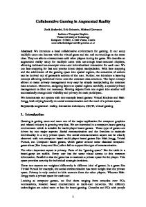
Fig. 1 Collaboratively designing a racing game using Raptor.
Fig. 2 Stamping a physical car on the table adds a virtual car into the game.
mined by building a game that people can play. Raptor allows groups of people to brainstorm around early game design. Designers use a tabletop surface to quickly sketch the game’s appearance and play. Meanwhile, a player can test the prototype as it is being built. Designers can use Raptor as a “Wizard of Oz” [5] tool, mocking up game interaction in real time. Unlike other game sketching tools [1], Raptor leverages modern interaction styles to support rapid interaction. The tabletop surface allows two or three people to closely collaborate in the design, and provides rapid and tactile facilities for quickly testing game ideas. As seen in figure 1, small groups of people surround the table, and work together in creating the game. Designers use physical, virtual and mixed reality objects. For example (somewhat similarly to Build-It [21]), physical objects can be used to add new instances of virtual objects into a scene. Figure 2 shows the addition of a car into a racing
4
Christopher Wolfe, J. David Smith, W. Greg Phillips and T.C. Nicholas Graham
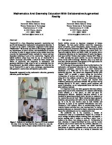
Fig. 3 Designers can manipulate the virtual terrain with physical gestures, e.g., using a scooping motion to create a hill.
Fig. 4 Designers and testers collaborate using Raptor.
game by “stamping” a physical car onto the tabletop. The virtual car is added to the scene at the location where the physical car is stamped. Similarly, physical objects can be augmented to show how they interact with the virtual world. In figure 1, a designer places an Xbox controller input device onto the table. A ring of “pins” surround the controller, representing the different input and output channels the controller provides (e.g., the different buttons and joysticks.)
Fiia: Engineering Collaborative Augmented Reality
5
Fig. 5 A tester can play a game as it is being created, creating a fluid testing process and supporting Wizard of Oz prototyping.
As the controller is moved around the tabletop surface, the ring of pins moves with it, creating a truly mixed physical-virtual entity. The pins on the controller can be connected to pins on other objects; the designer attaches the “A” and “B” buttons to the car’s gas pedal and brake pins, allowing these buttons to be used to accelerate and decelerate. To connect two pins, the designer touches the source pin, and then touches the target pin. A line is drawn between them to show the connection. Physical gestures can be used to manipulate the virtual game world; a scooping motion with the hands can be used to “drag” the terrain, creating a hill (figure 3). This style of input allows the designer to interact with virtual entities using physical actions. These examples show how the tabletop enables a fluid interaction between physical and virtual entities. These interactions include using physical artifacts as props (stamping); augmenting physical artifacts with virtual properties (the ring of pins); and using physical interactions to manipulate virtual artifacts (sculpting terrain.) Testers can play the game as it is being designed. Figure 4 shows a tester sitting at a PC playing the game as the designers modify it. For example, if the designers are creating a racing game, then the tester immediately sees changes such as adding a new car to the game, repositioning an obstacle or modifying the terrain. Similarly, changes in gameplay are reflected immediately in the tester’s view of the game: for example, the controls used to manipulate a car can be changed on the fly. This
6
Christopher Wolfe, J. David Smith, W. Greg Phillips and T.C. Nicholas Graham
allows a “Wizard of Oz” style of gameplay testing, in which designers can simulate the game by manipulating objects on the table. This approach allows a tester to experience a game idea without the expense of fully implementing it. Testers and designers have different viewpoints on the game. Designers have a top-down, two-dimensional view of the game world (figure 4), while testers see the game in a more traditional 3D form (figure 5). Raptor shows the richness of interaction that can be achieved with collaborative augmented reality. As described above, the physical and virtual worlds can interact in a number of interesting ways, through the use of physical objects as props, the augmentation of physical objects with virtual properties, and the use of physical gestures to manipulate virtual entities. Collaboration can be of the form of a group of designers around a table, using pointing, gesturing and speech to mediate their actions, or between testers and designers sitting at different locations in the room, interacting via different views of the same shared artifacts. A particular strength of Raptor is that not all users need to have hardware capable of delivering an AR experience. Here, the tester interacts with the game using a standard PC. Initial tests with Raptor have shown that the tabletop-based AR interaction is natural, not unlike interaction between people sitting around a traditional table, and that the collaboration is fluid, with people easily shifting between roles of designer and tester. This example illustrates many of the benefits of collaborative augmented reality. In the remainder of the chapter, we introduce the Fiia.Net toolkit, and illustrate how it was used to implement Raptor. We then discuss the implementation of the toolkit itself. First, we review other techniques for the design and implementation of collaborative AR applications.
3 Related Work The design of Fiia draws from a wealth of prior research in modeling notations and toolkits for developing collaborative AR applications.
3.1 Modeling Collaborative Augmented Reality The Fiia design notation is an architectural style, a visual notation from which software architectures for collaborative AR are constructed. Several other architectural styles have the goal of reducing the difficulty of programming groupware (collaborative applications) or augmented reality applications. To date, we are unaware of other architectural styles that attempt to provide support for both. Architectural styles provide rules for decomposing groupware systems into components, allowing developers to use a “divide and conquer” development approach. For example, both the Clover Model [13] and PAC* [4] give advice on how to split
Fiia: Engineering Collaborative Augmented Reality
7
up user interface and application, while supporting group tasks of production, communication and coordination. These architectures are conceptual, meaning that they do not address the problems of how to implement them on distributed systems. Developers, therefore, face a significant task to convert them to running code. Phillips provides a detailed survey of conceptual architecture styles for groupware [19]. Among architectural styles for augmented reality applications, notable is ASUR [6]. Similarly to our own approach, ASUR allows applications to be modeled via scenarios, where ASUR diagrams consist of components and connectors. ASUR explicitly recognizes adapters, components that bridge between the physical and virtual worlds. ASUR is purely a modeling notation; while ASUR models form an excellent guide to developers, they are not themselves executable, and must be converted by hand to code. ASUR does not provide explicit support for collaboration.
3.2 Toolkits for Collaborative AR There exist numerous toolkits for developing groupware, and several for writing AR applications. We are unaware of any toolkit that provides support for both. Most groupware toolkits (such as Groupkit [22], ALV [11] and Clock [24]) require all users to interact with the application in the same way, and so could not be used to implement Raptor’s heterogeneous roles and platforms. The .Networking shared dictionary [15] does provide flexible support for heterogeneous clients. Several groupware toolkits provide some support for dynamic adaptation, which could be used to implement transition between scenes. Schmalsteig et al. provide an approach for client migration in virtual reality applications [23]. A shared scene graph datastructure is implemented via replication. The code and scene graph can be migrated to new client computers, providing a form of device adaptation. DACIA [14] is a middleware which provides support for component migration; it can be used to manually program adaptation at a level considerably higher than raw networking libraries. Genie [2] supports adaptivity by allowing the definition of distributed system configurations (including replication and caching strategies) and automatic migration between them. Most toolkits for developing augmented reality applications address the specific problem of determining camera’s position and orientation (or “pose”) and determining the location of physical objects. An example of this problem is tracking the location of the physical Xbox 360 controller on the tabletop so that its pins can be drawn around it (figure 1); another example is determining the position and orientation of a head-mounted display. Augmented reality toolkits are typically presented as libraries that can be used from a range of host programming languages. For example, users of ARToolkit [12] and ARTag [7] attach patterned images (tags) to the environment. These are programmatically linked to entities in the virtual world. The pose of the camera in the physical world can be determined by analyzing the position of the tags in the image provided by the camera. GoblinXNA takes a similar approach, while providing integration with Microsoft’s XNA studio game develop-
8
Christopher Wolfe, J. David Smith, W. Greg Phillips and T.C. Nicholas Graham
ment environment [17]. Other problems addressed by toolkits can include localization, gesture recognition, and graphics [9]. While each of these approaches helps the problem of developing collaborative AR applications, work still remains to be done. The groupware approaches we have reviewed either (i) are high-level but provide little support for the problems of distributed systems programming, or (ii) provide programming help, but are not linked to a specific architectural style. Meanwhile, the augmented reality toolkits provide highly valuable libraries, but do not provide support at the architectural or design level. As we shall see, Fiia can be seen as a generalization of these approaches that provides far more flexibility at both the conceptual and distribution architectural levels, while providing necessary facilities for composing AR applications. From this brief survey of related work, we can see the need for a toolkit like Fiia which allows high-level design of collaborative AR applications, and provides highly flexible tool support for implementing those designs.
4 Fiia Notation Fiia is a design notation for collaborative AR applications, supported by a toolkit (Fiia.Net) for realizing these designs as running applications. Fiia is a model-based approach, allowing a high-level conceptual model of the system to be automatically implemented as a distributed application involving both physical and virtual artifacts. Compared to earlier approaches, Fiia makes three principal advances, providing: • A high-level notation for modeling both groupware and augmented reality, including features for data sharing and virtual/physical adapters; • Scenario-based design and implementation; • Easy transition from models to code. We address each of these points in the following three sections.
4.1 Notation for Collaborative AR Figure 6 shows an example Fiia diagram for Raptor. Designers interact with an Editor, which allows them to manipulate the scene, shaping the terrain, adding game elements (such as cars and controllers), and attaching behaviours to those elements. Elements are represented in the form of a “scene graph”, a data structure capturing properties such as the elements’ positions, geometry and textures. The scene graph is stored in the Scene component. The Editor is an Actor ( ) component, that is, a component capable of initiating action; Scene is a Store ( ) component, i.e., a passive data store.
9
Scene
Scene
Editor
Displayer
Table A Surface
Designer
Display
Game PC
Tabletop PC
Fiia: Engineering Collaborative Augmented Reality
A
Tester
Fig. 6 Fiia model of Raptor’s initial scene
Designers interact with the Editor via a tabletop surface, represented by the Table Surface adapter component. The Table Surface provides input/output facilities for the physical tabletop (a Microsoft Surface [16]). The designer interacts with the Table Surface via a bi-directional flow of information. This is represented by a pair of Fiia stream connectors: . (These connectors have been abbreviated in the figure as a double-ended stream.) The Editor polls the tabletop for its current state (via a call connector: ), and updates the table’s display via a stream connector. In general, streams represent asynchronous dataflow, and are useful for communicating discrete events or continuous media such as sound or video, while call connectors are used to represent traditional synchronous method calls. Meanwhile, testers view the running game on a Display. A Displayer actor keeps the display up to date, responding to changes in the Scene. The tester and displayer’s ). versions of the Scene are kept consistent via a synchronization connector ( This connector is used to specify that two or more stores are to be maintained in a consistent state, so that changes in one are automatically reflected in the other. Fiia diagrams are implemented as distributed systems. Here, at least two computers must be used: the computer running the tabletop surface (Tabletop PC) and the tester’s computer (Game PC). Fiia diagrams, however, do not specify the details of this distribution. They abstract the allocation of components to computational nodes, the algorithms used to transmit data between nodes, and the consistency maintenance schemes used to implement data synchronization. As we will see in section 6, the Fiia.Net toolkit automatically determines a distribution from the high-level Fiia diagram. This allows designers to concentrate on the function of their application without having to be mired in the details of their distributed implementation.
10
Christopher Wolfe, J. David Smith, W. Greg Phillips and T.C. Nicholas Graham component user
store: passive, shareable reactor: passive
one of: A
actor: independently active adapter: physical to virtual
setting call: blocking, one-to-one, can return values stream: non-blocking, many-to-many, send only synchronize: observational equivalence of stores
Fig. 7 The Fiia notation
The symbols used in Fiia diagrams are summarized in figure 7. Fiia diagrams have two features that particularly help in the development of collaborative AR applications: adapters and synchronization connectors. We detail these features in the next two sections.
4.1.1 Adapters Dubois and Gray’s ASUR notation first introduced the concept of adapters [6], software architectural components that bridge between the physical and virtual worlds. Adapters can represent traditional devices (such as a keyboard or display), or more novel devices such as tabletop surfaces, accelerometers, cameras or head-mounted displays. Adapters are core to the specification of augmented reality applications, as they clearly specify the interaction between the physical and virtual worlds. Fiia’s adapter (“ A”) components are similar in concept to those of ASUR, representing the boundary between the physical and virtual worlds. From the toolkit’s perspective, adapters are actually software components that encapsulate the interface to an interaction device. For example, the Table Surface component implements the services required to interact with the tabletop surface, including object recognition, gesturing, and tabletop display. Specifically, the Table Surface contains functions to recognize the position and orientation of tagged physical artifacts (such as the car and controller) when they are placed on the surface. This allows implementation of Raptor’s “stamping” function (figure 2) and of the mixed reality controller (figure 1). The component is capable of interpreting multi-touch inputs as gestures, allowing implementation of gesture-based dragging and rotating of virtual game elements, as well as terrain sculpting (figure 3). As illustrated by figure 6, adapters must be anchored to specific nodes, so that the Fiia.Net toolkit can determine which physical device is intended. The Fiia.Net toolkit supports a variety of interesting adapters, including mouse, keyboard, Xbox 360 controller, video camera, microphone, speaker and display. Adapters under development include Wii Remote, and GPS. It is possible to create
Fiia: Engineering Collaborative Augmented Reality
11
Scene
Scene
Car
Table A Surface
Controller
Designer
Displayer
A
Display
Game PC
Tabletop PC
Editor
A
Tester
Fig. 8 Result of designer “stamping” a new car into the game.
sophisticated applications through these rich adapters. For example, taking advantage of the fact that Fiia connectors can span node boundaries, a video broadcast can be created simply by connecting a camera in one location to a screen in another.
4.1.2 Data Sharing The second way in which Fiia provides high-level support for collaborative AR is through the synchronization connector (“ ”). This connector, first introduced as a notational convenience in Patterson’s taxonomy of groupware architectures [18], specifies that two data stores are to retain observational equivalence throughout the execution of the program (or more simply, that the runtime system must make a best effort to ensure that both stores have the same value.) Specifically, all requests to either store must return the same value, all updates to one store must be reflected in the other, and event streams originating from the stores must be equivalent. Synchronization provides basis for implementing artifact sharing. Participants can access shared data, allowing customized interfaces. For example, the tester’s display shows the game from a 3D perspective, while the designer sees the game top-down on a tabletop surface. The power of Fiia’s data synchronization is that it does not require the designer to specify how the synchronization is to occur. The connector hides decisions of replication (centralized versus replicated data), networking algorithms and consistency maintenance schemes.
12
Christopher Wolfe, J. David Smith, W. Greg Phillips and T.C. Nicholas Graham
4.2 Scenario-Based Design The process of modeling with Fiia is high-level, based on identifying and linking typical execution steps. Developers start by identifying scenarios of their system’s use. From these scenarios, they determine example snapshots of the system in use. The developer then creates Fiia diagrams representing interesting situations, and finally (as we shall see in section 4.3), transforms them into code. For example, in Raptor, the scenario begins (as shown in figure 6) with the designer manipulating the game and the tester viewing the results. In the second step (figure 8), the designer has “stamped” a car into the game, and an Xbox 360 controller has been added allowing the tester to drive the car. A new Car component is dynamically added to the Fiia architecture. This component contains all knowledge of the new car’s behaviour – how it responds to user inputs (e.g., that the “A” button causes the car to accelerate), and its physics (e.g., how acceleration affects speed.) The car’s behaviour causes changes in the Scene, allowing the car to be rendered (by the Editor and Displayer components.) A new Controller adapter is added to the diagram, representing the physical Xbox 360 controller that will be used to manipulate the car. The tester provides this input. The Car polls the state of the controller during every new game frame, using the input to update the car’s position. The controller can be used by either the designer or tester, and in fact is frequently passed from one to the other during prototyping sessions. Controller inputs cause the position of the car to move both on the tabletop and on the game PC display. Despite the fact that the controller is shared, it must be explicitly anchored to either the tabletop PC or the game PC so that the runtime system can identify which controller is intended. The Fiia.Net toolkit provides high-level operations for moving between stages of a scenario; e.g., adding and connecting new components can be carried out with one-line operations, even when those operations implicitly involve migrating data over a network. Fiia diagrams such as those of figures 6 and 8 help in documenting how the collaborative AR application may change during execution. Developers must then write code using the Fiia.Net toolkit to render these scenes into code.
Fiia: Engineering Collaborative Augmented Reality
13
4.3 Mapping Fiia Diagrams to Code As we have seen, Fiia diagrams follow naturally from scenarios. It is straightforward to map diagrams to code; the concepts from Fiia diagrams map one-to-one to C# code using the Fiia.Net toolkit. For example, the following code creates the Scene component for the designer and synchronizes it to the equivalent component for the tester: Store scene = Fiia.NewStore(); SyncConnector sync = Fiia.SyncConnect( "SceneSync", scene ); The Scene class is a standard C# class, providing operations for adding and editing elements of the game’s scene graph. The following code creates the the Editor and adds the call connector between it and the Scene store: Actor editor = Fiia.NewActor(); Fiia.CallConnect( editor.Property("Scene"), scene.Interface("IScene") ); The Editor is implemented by the C# Editor class. The call connection establishes its Scene property as a reference in the scene component; this reference enables inter-component calls using standard C# syntax, such as scene.AddNode(...); Streams are created similarly to call connectors, using either interfaces or C#’s standard delegate event handlers. Adapters, like stores and actors, are created from C# classes. Rather than application code, they implement access to the physical device. The Fiia.Net toolkit provides a library of such adapters, ranging over standard devices such as mouse and keyboard, to richer devices such as tabletop surfaces and game controllers. More adapters are being added to the toolkit regularly. We see from these examples that mapping from Fiia diagrams to code is straightforward, as each element of the Fiia diagram has a corresponding concept in the Fiia.Net API. The toolkit builds naturally on features familiar to C# programmers, and has been integrated with Windows forms (for traditional graphical user interfaces) and XNA Studio (for 2D and 3D games and simulations.) Fiia.Net runs on a wide variety of platforms, including PCs, Windows Mobile PDAs and (forthcoming) the Xbox 360 game console.
14
Christopher Wolfe, J. David Smith, W. Greg Phillips and T.C. Nicholas Graham
4.4 Summing up the Fiia Notation As we have seen, the Fiia notation allows straightforward modeling of collaborative AR applications. The notation is high-level, abstracting details of distributed systems and non-traditional I/O devices. This allows developers to concentrate on the high-level structure of their application without having to be concerned with low-level implementation details. Two features of the Fiia notation particularly help with this: the synchronization connector allows data to be shared by different users of the system; and the adapter construct allows easy specification of the boundaries between the physical and virtual worlds. The Fiia.Net toolkit automatically implements data synchronization, identifying appropriate replication, networking and concurrency control algorithms. Similarly, Fiia.Net provides a library of adapters for a range of I/O devices including the table surface, Xbox 360 controller and display used in this example. The approach allows designers to sketch their application via a connected set of scenes, each expressed as a Fiia diagram. These diagrams are easily translated to code, as each of the diagram elements and diagram adaptations are directly represented in the Fiia.Net library.
5 The Fiia.Net Toolkit As discussed in the previous section, Fiia diagrams abstract the details of application distribution and adapter implementation. This allows developers to concentrate on the functionality of their application rather than on low-level issues of network programming and image processing. In this section, we show how Fiia.Net automatically maps Fiia diagrams to distributed systems, implements transitions between scenario steps, and realizes adapters. In section 6, we provide a brief overview of how Fiia.Net itself is implemented.
5.1 Conceptual Framework Figure 9 shows Fiia.Net’s conceptual organization. Programmers create a Fiia diagram ( f ) representing their scene, using the techniques described above. This diagram is automatically refined by Fiia.Net to a distribution architecture (d). Runtime transitions may occur at both the Fiia level (change application, device, location, etc.) or at the distribution level (network or component failure.) This leads to a new Fiia or distribution architecture ( f 0 or d 0 .) The toolkit then carries out necessary operations to reestablish consistency between the two levels. To our knowledge, Fiia.Net is unique in maintaining this two-level view of the system at runtime, and in automatically maintaining consistency between the two views. This
Fiia: Engineering Collaborative Augmented Reality
f
af
r
d
15
f’
conceptual level
r’
ad scene transition
d’
refinement
distribution level
Fig. 9 Fiia Framework
allows developers to enact runtime change using high-level Fiia scenes. It also allows gives developers the means to deal with partial failure at a high level. Rather than dealing with repair of broken sockets, programmers view failure as the disappearance of components and connectors, making it easier to respond to a failure in its broader context. Having established this framework, we next examine the elements of Fiia’s distribution architecture and discuss how runtime adaptation is enacted. We then review the implementation of the Fiia.Net toolkit and present our experience with its use.
5.2 Distribution Architecture Figure 10 shows the distribution architecture for the Raptor configuration that was shown in figure 8. This level of architecture pins down details of how the Fiia design is implemented as a distributed system. The distribution architecture is automatically generated by the Fiia.Net toolkit from the Fiia design provided by the programmer. As will be discussed, the distribution architecture is continuously updated at runtime in response to programmer-directed changes to the Fiia design and system-directed changes in the networking infrastructure. Distribution architectures are expressed in terms of infrastructure components (figure 11.) These include implementations of the components specified in the Fiia design, as well as built-in components that handle issues such as caching, concurrency control and communication. In effect, these components make up a machine language for distribution architectures, to which the Fiia.Net refinery compiles Fiia designs.
16
Christopher Wolfe, J. David Smith, W. Greg Phillips and T.C. Nicholas Graham
Tabletop PC
Game PC
n
Scene
Editor
Table A Surface
Controller
Designer
n
Car
Scene
Displayer
A
Display
A
Tester
Fig. 10 Distribution architecture for the Raptor diagram of figure 8
The distribution architecture differs from the Fiia design in several ways, including: • Components are allocated to computational nodes. For example, the Editor is represented on the Tabletop PC, while the Displayer is allocated to the game PC. • It is determined how components communicate over the network. For example, the two instances of the Scene component use a multicast channel to communicate. • Support for replica consistency is added in the form of infrastructure components that provide a choice of concurrency control and consistency maintenance algorithms. We now examine the specifics of this architecture in order to illustrate the range of issues that Fiia designs hide from the application programmer. We emphasize that figure 10 shows one of many possible distribution architectures for the Fiia design of figure 8. The Editor and the Displayer each require access to data in the Scene component, which is replicated to both the tabletop and game PCs. Each instance of the Scene can be updated by both the local and remote user interfaces (in response to the designer and tester’s inputs). Therefore, Consistency Maintenance/Concurrency Control (CCCM) components are required to ensure consistent execution of operations on the two replicas. CCCM’s are shown visually as: .
Fiia: Engineering Collaborative Augmented Reality
17
concurrency control and consistency maintenance (CCCM)
application component
asynchronous message broadcaster
cache
point-to-point network receiver
mirror cache
point-to-point network transmitter local call
n
many-to-many network channel
node
remote call
Fig. 11 Elements from which Fiia distribution architectures are constructed
The CCCM components use an internal protocol based on message broadcasting to maintain the consistency of the replicas. The CCCMs communicate via a channel ( ), which provides multicast messaging. In summary, the distribution architecture is a rich language allowing the expression of a wide range of distributed implementations. Not shown here is the range of implementations Fiia.Net provides for infrastructure components, which encapsulate, for example, choice of concurrency control algorithm or networking protocol. n
5.3 Adapters Fiia’s adapters allow high-level specification of the points of transition between the physical and virtual worlds. Fiia.Net provides a library of reusable adapters. When these are used in Fiia diagrams, they can be automatically inserted components into the runtime architecture. It is of course straightforward for developers to add custom adapters to the library. Adapters are typically built over existing libraries for common tasks such as interpreting gestures, object recognition, camera pose, and so forth. As was seen in the Fiia diagrams of figures 6 and 8, adapters are explicitly anchored to a node. This allows Fiia.Net to determine which computer the adapter code is referencing. An advantage of Fiia’s distribution independence is that adapters can be used by components on other nodes without requiring special network programming. For example, the Editor component does not need to be on the same node as the Table Surface adapter (although it happens to be in the refinement shown in figure 8.)
18
Christopher Wolfe, J. David Smith, W. Greg Phillips and T.C. Nicholas Graham
Infrastructure
Refinement
Application & Middleware Components
Architect
Node Manager
Builder
Conceptual Model Refinery Distribution Model
Fig. 12 Implementation of the Fiia.Net runtime system
setting
in
component
in node
anchored-to +++
Fig. 13 The anchor rule
6 Implementing Fiia In the previous section, we saw how the Fiia.Net runtime implements Fiia diagrams. The toolkit automatically handles distributed systems issues such as component allocation, networking and consistency maintenance, and provides implementations of common adapters, as well as providing high-level support for migration between scenes. We now briefly review how Fiia.Net itself is implemented. Figure 12 shows the runtime architecture of the Fiia.Net system. Every node has a Node Manager component responsible for configuring local objects as directed by the Refinery. One “master” node has the special status of being responsible for storing the conceptual and distribution architectures (the Architecture component), and manging the consistency between them. The Architect carries out conceptual-level changes to the architecture (e.g. create a new workspace and adding components), and notifies the Refinery. The Refinery is a rule-based system responsible for mapping the Fiia architecture to a distributed implementation, taking into account any specified attributes. Figure 13 shows an example of one of the refinery’s rules, specifying how components are anchored to a node. Rules are written in Story Diagram notation [8]. This rule states that a Fiia component located within some setting may be anchored to any node that is contained within the same setting. The Fiia.Net runtime contains 34 rules. The refinery applies these rules repeatedly to the Fiia architecture until no
Fiia: Engineering Collaborative Augmented Reality
19
more rules match. We have proven (via structural induction over the ruleset) that this process always terminates with a valid distribution architecture [20]. The chain of rule applications represents the refinement trajectory that we saw in figure 9. In the case of partial failure of the distributed system, any rule steps that are no longer valid are unwound, ultimately removing from the Fiia architecture any components or connectors that are no longer valid.
7 Experience The Fiia.Net toolkit has been implemented and used to develop a range of applications. These include Raptor (as described in this chapter), a collaborative furniture layout program (involving tabletop design of the furniture layout, and interaction with the design by collaborators using PC and Smartphone), a distributed slide presentation system, an instant messaging system, and a voice over IP communication tool. These applications involve a wide range of interaction styles and devices. We have found that developers require tutoring to understand how to structure applications around Fiia scenes, but are productive once they have learned the style. Fiia diagrams are significantly different from the UML class diagrams with which most developers are familiar. Class diagrams represent a general case, whereas Fiia diagrams represent a specific runtime snapshot of the system. Class diagrams focus on inheritance and aggregation structures, while Fiia diagrams represent communication patterns, data sharing and interfaces between the physical and virtual worlds. (Class diagrams, of course, have no way of expressing runtime scenes or transitions between them, and so are inadequate for modeling collaborative augmented reality.) Once developers have learned how to think of applications in terms of scenario steps linked by runtime transition, we have found them to be able to productively work with the Fiia notation. The runtime performance of Fiia.Net applications is excellent, sometimes exceeding that of the standard .Net libraries. We implemented Raptor using both Fiia and standard .Net Remoting. In the .Net case, there was noticeable latency between the designer (tabletop) and tester (game PC) views. With the Fiia implementation, there was no perceptible delay. This shows that it is possible to implement applications using a conceptual model as abstract as Fiia’s, while winning excellent performance. The speed of performing adaptations, however, is considerably slower. A single element can be added to the scene with only a slight delay as the Fiia.Net refinery computes and deploys the appropriate distribution architecture. However, when adding dozens of elements rapidly (with multiple designers repeatedly stamping as many new elements into the scene as quickly as they can), Fiia.Net can take as many as tens of seconds to refine the new architecture. We expect over time to dramatically improve this performance by deploying improved graph rewriting algorithms in the refinery.
20
Christopher Wolfe, J. David Smith, W. Greg Phillips and T.C. Nicholas Graham
Our next steps are to continue to improve the implementation of Fiia.Net, and to extend it to further platforms such as the Xbox 360 and the Microsoft Zune. Using the Mono implementation of Microsoft .Net, it should further be possible to extend Fiia.Net to other platforms such as the Macintosh and Linux.
8 Conclusion In this chapter, we have introduced Fiia, a visual notation for expressing the design of collaborative AR applications. We have shown that Fiia allows applications to be specified at a high level reminiscent of scenarios. The Fiia.Net toolkit can then be used to implement these scenarios and the transitions between them. As we have shown, Fiia.Net resolves the issues of how applications are implemented as distributed systems involving a range of physical devices.
Acknowledgements This work benefitted from the generous support of the Natural Science and Engineering Research Council of Canada, and NECTAR, the Network for Effective Collaboration Technologies through Advanced Research.
References 1. Agustin, M., Chuang, G., Delgado, A., Ortega, A., Seaver, J., Buchanan, J.: Game sketching. In: Proceedings of the Second International Conference on Digital Interactive Media in Entertainment and Arts, pp. 36–43 (2007) 2. Bencomo, N., Blair, G., Grace, P.: Models, reflective mechanisms and family-based systems to support dynamic configuration. In: MODDM ’06, pp. 1–6. ACM Press (2006) 3. Bjork, S., Holopainen, J.: Patterns in Game Design. Charles River (2004) 4. Calvary, G., Coutaz, J., Nigay, L.: From single-user architectural design to PAC*: A generic software architecture model for CSCW. In: Proc. CHI ’97, pp. 242–249. ACM Press (1997) 5. Dahlb¨ack, N., J¨onsson, A., Ahrenberg, L.: Wizard of Oz studies: why and how. In: IUI ’93: Proceedings of the 1st international conference on Intelligent User Interfaces, pp. 193–200. ACM (1993) 6. Dubois, E., Gray, P.: A design-oriented information-flow refinement of the ASUR interaction model. In: Engineering Interactive Systems. Springer LNCS (2007) 7. Fiala, M.: ARTag, a fiducial marker system using digital techniques. Computer Vision and Pattern Recognition, IEEE Computer Society Conference on 2, 590–596 (2005) 8. Fischer, T., Niere, J., Torunski, L., Z¨undorf, A.: Story diagrams: A new graph rewrite language based on the Unified Modeling Language and Java. In: Proc. TAGT’98, pp. 296–309. Springer-Verlag (2000) 9. Fisher, S.S.: An authoring toolkit for mixed reality experiences. In: Proceedings of the International Workshop on Entertainment Computing (IWEC2002): Special Session on Mixed Reality Entertainment, pp. 487–494 (2002)
Fiia: Engineering Collaborative Augmented Reality
21
10. Graham, T.C.N., Roberts, W.: Toward quality-driven development of 3D computer games. In: Proceedings of the Thirteenth International Workshop on Design, Specification and Verification of Interactive Systems, pp. 248–261. Springer LNCS (2006) 11. Hill, R., Brinck, T., Rohall, S., Patterson, J., Wilner, W.: The Rendezvous language and architecture for constructing multi-user applications. ACM TOCHI 1(2), 81–125 (1994) 12. Kato, H., Billinghurst, M.: Marker tracking and hmd calibration for a video-based augmented reality conferencing system. In: Proceedings of the 2nd International Workshop on Augmented Reality (IWAR 99) (1999) 13. Laurillau, Y., Nigay, L.: Clover architecture for groupware. In: CSCW ’02, pp. 236–245. ACM Press (2002) 14. Litiu, R., Zeitoun, A.: Infrastructure support for mobile collaboration. In: HICSS ’04. IEEE CS (2004) 15. McEwan, G., Greenberg, S., Rounding, M., Boyle, M.: Groupware plug-ins: A case study of extending collaboration functionality through media items. In: Proc. CollabTech 2006, pp. 42–47 (2006) 16. Microsoft: Surface. Http://www.microsoft.com/surface 17. Oda, O., Lister, L.J., White, S., Feiner, S.: Developing an augmented reality racing game. In: INTETAIN ’08: Proceedings of the 2nd international conference on INtelligent TEchnologies for interactive enterTAINment, pp. 1–8. ICST (Institute for Computer Sciences, SocialInformatics and Telecommunications Engineering) (2007) 18. Patterson, J.: A taxonomy of architectures for synchronous groupware applications. ACM SIGOIS Bulletin Special Issue: Papers of the CSCW’94 Workshops 15(3), 27–29 (1995) 19. Phillips, W.G.: Architectures for synchronous groupware. Tech. Rep. 1999-425, Queen’s University, Kingston, Ontario, Canada (1999) 20. Phillips, W.G.: The Workspace Model: Dynamic distribution of interactive systems. Phd thesis, Queen’s University (2006) 21. Rauterberg, M., Fjeld, M., Krueger, H., Bichsel, M., Leonhardt, U., Meier, M.: BUILD-IT: a computer vision-based interaction technique for a planning tool. In: HCI’97, pp. 303–314. Springer-Verlag (1997) 22. Roseman, M., Greenberg, S.: Building real time groupware with GroupKit, a groupware toolkit. TOCHI 3(1), 66–106 (1996) 23. Schmalstieg, D., Hesina, G.: Distributed applications for collaborative augmented reality. In: Proc. VR ’02, pp. 59–67. IEEE CS (2002) 24. Urnes, T., Graham, T.C.N.: Flexibly mapping synchronous groupware architectures to distributed implementations. In: Proceedings of the Sixth Eurographics Workshop on Design, Specification and Verification of Interactive Systems (DSV-IS ’99), pp. 133–148 (1999)