Failure Modes, Effects and Diagnostic Analysis Project: 2051 Pressure Transmitter Company: Rosemount Chanhassen, MN USA
Contract Number: Q07/10-08r2 Report No.: Rosemount 07/10-08 R001 Version V1, Revision R1, April 29, 2008 Rudolf Chalupa
The document was prepared using best effort. The authors make no warranty of any kind and shall not be liable in any event for incidental or consequential damages in connection with the application of the document. © All rights reserved.
Management Summary This report summarizes the results of the hardware assessment in the form of a Failure Modes, Effects, and Diagnostic Analysis (FMEDA) of the 2051 Pressure Transmitter, hardware revision 1 and software revision 178. A Failure Modes, Effects, and Diagnostic Analysis is one of the steps to be taken to achieve functional safety certification per IEC 61508 of a device. From the FMEDA, failure rates and Safe Failure Fraction are determined. The FMEDA that is described in this report concerns only the hardware of the 2051. For full functional safety certification purposes all requirements of IEC 61508 will be considered. The 2051 is a pressure transmitter, or more accurately a series of pressure transmitters, utilizing either a capacitive (2051C) sensor in differential or gage modes or a resistive bridge (2051T) sensor in absolute or gage mode. The 2051C has dual interface diaphragms and can interface to a manifold; wherease the 2051T has a single process connection. Both transmitters are microprocessor-based and contain internal diagnostics as well as the ability to communicate via the HART digital protocol. For safety applications only the 4 to 20mA output is considered. Other outputs are not covered by this report. Table 1 gives an overview of the different versions that were considered in the FMEDA of the 2051. Table 1 Version Overview
2051C
Capacitive Sensor, Differential or Gage
2051T
Resistive Bridge Sensor, Absolute or Gage
The 2051 is classified as a Type B 1 device according to IEC 61508, having a hardware fault tolerance of 0. The analysis shows that the device has a Safe Failure Fraction between 60% and 90% (assuming that the logic solver is programmed to detect over-scale and under-scale currents) and therefore may be used up to SIL 1 as a single device based on hardware architectural constraints. The complete sensor subsystem, of which the 2051 is the sensor, will need to be evaluated to determine the Safe Failure Fraction. The failure rates for the 2051 are listed in Table 2 and Table 3.
1
Type B device: “Complex” component (using micro controllers or programmable logic); for details see 7.4.3.1.3 of IEC 61508-2. © exida Consulting LLC Rudolf Chalupa
Rosemount 07-10-08 FMEDA Report 2051 R001 V1 R1.doc Page 2 of 20
Table 2 Failure rates 2051C
Failure Category
Failure Rate (FIT) 0.0
Fail Safe Undetected
227.9
Fail Dangerous Detected Fail Detected (detected by internal diagnostics)
174.0
Fail High (detected by logic solver)
31.0
Fail Low (detected by logic solver)
22.9
Fail Dangerous Undetected
46.4
Residual
63.4 6.3
Annunciation Undetected Table 3 Failure rates 2051T
Failure Category
Failure Rate (FIT) 0.0
Fail Safe Undetected
253.7
Fail Dangerous Detected Fail Detected (detected by internal diagnostics)
194.9
Fail High (detected by logic solver)
35.9
Fail Low (detected by logic solver)
22.9
Fail Dangerous Undetected
49.0
Residual
74.9
Annunciation Undetected
10.3
These failure rates are valid for the useful lifetime of the product, see Appendix A. The failure rates listed in this report do not include failures due to wear-out of any components. They reflect random failures and include failures due to external events, such as unexpected use, see section 4.2.2. Table 4 lists the failure rates for the 2051 according to IEC 61508.
© exida Consulting LLC Rudolf Chalupa
Rosemount 07-10-08 FMEDA Report 2051 R001 V1 R1.doc Page 3 of 20
Table 4 Failure rates according to IEC 61508
Device
λSD
λSU2
2051C
0 FIT
70 FIT
228 FIT
46 FIT
86.6%
2051T
0 FIT
85 FIT
254 FIT
49 FIT
87.4%
λDD
λDU
SFF3
A user of the 2051 can utilize these failure rates in a probabilistic model of a safety instrumented function (SIF) to determine suitability in part for safety instrumented system (SIS) usage in a particular safety integrity level (SIL). A full table of failure rates is presented in section 4.4 along with all assumptions.
2
It is important to realize that the Residual failures are included in the Safe Undetected failure category according to IEC 61508. Note that these failures on their own will not affect system reliability or safety, and should not be included in spurious trip calculations
3
Safe Failure Fraction needs to be calculated on (sub)system level
© exida Consulting LLC Rudolf Chalupa
Rosemount 07-10-08 FMEDA Report 2051 R001 V1 R1.doc Page 4 of 20
Table of Contents Management Summary ....................................................................................................... 2 1
Purpose and Scope...................................................................................................... 6
2
Project Management .................................................................................................... 7 2.1
exida ................................................................................................................................7
2.2
Roles of the parties involved ............................................................................................7
2.3
Standards and Literature used .........................................................................................7
2.4
Reference documents......................................................................................................8
2.4.1
Documentation provided by Rosemount.......................................................................8
2.4.2
Documentation generated by exida .............................................................................8
3
Product Description ...................................................................................................... 9
4
Failure Modes, Effects, and Diagnostic Analysis........................................................ 10
5
4.1
Failure Categories description........................................................................................10
4.2
Methodology – FMEDA, Failure Rates ...........................................................................11
4.2.1
FMEDA ......................................................................................................................11
4.2.2
Failure Rates..............................................................................................................11
4.3
Assumptions ..................................................................................................................12
4.4
Results...........................................................................................................................12
Using the FMEDA Results.......................................................................................... 15 5.1
PFDAVG Calculation 2051 ...............................................................................................15
6
Terms and Definitions ................................................................................................ 16
7
Status of the Document.............................................................................................. 17 7.1
Liability...........................................................................................................................17
7.2
Releases........................................................................................................................17
7.3
Future Enhancements....................................................................................................17
7.4
Release Signatures........................................................................................................18
Appendix A
Lifetime of Critical Components................................................................ 19
Appendix B
Proof tests to reveal dangerous undetected faults ................................... 20
B.1
Suggested Proof Test ....................................................................................................20
© exida Consulting LLC Rudolf Chalupa
Rosemount 07-10-08 FMEDA Report 2051 R001 V1 R1.doc Page 5 of 20
1 Purpose and Scope Generally three options exist when doing an assessment of sensors, interfaces and/or final elements. Option 1: Hardware assessment according to IEC 61508 Option 1 is a hardware assessment by exida according to the relevant functional safety standard(s) like IEC 61508 or EN 954-1. The hardware assessment consists of a FMEDA to determine the fault behavior and the failure rates of the device, which are then used to calculate the Safe Failure Fraction (SFF) and the average Probability of Failure on Demand (PFDAVG). When appropriate, fault injection testing will be used to confirm the effectiveness of any self-diagnostics. This option provides the safety instrumentation engineer with the required failure data as per IEC 61508 / IEC 61511. This option does not include an assessment of the development process. Option 2: Hardware assessment with proven-in-use consideration per IEC 61508 / IEC 61511 Option 2 extends Option 1 with an assessment of the proven-in-use documentation of the device including the modification process. This option for pre-existing programmable electronic devices provides the safety instrumentation engineer with the required failure data as per IEC 61508 / IEC 61511. When combined with plant specific proven-in-use records, it may help with prior-use justification per IEC 61511 for sensors, final elements and other PE field devices. Option 3: Full assessment according to IEC 61508 Option 3 is a full assessment by exida according to the relevant application standard(s) like IEC 61511 or EN 298 and the necessary functional safety standard(s) like IEC 61508 or EN 954-1. The full assessment extends Option 1 by an assessment of all fault avoidance and fault control measures during hardware and software development. This option provides the safety instrumentation engineer with the required failure data as per IEC 61508 / IEC 61511 and confidence that sufficient attention has been given to systematic failures during the development process of the device. This assessment shall be done according to option 1. This document shall describe the results of the hardware assessment in the form of the Failure Modes, Effects and Diagnostic Analysis carried out on the 2051. From this, failure rates, Safe Failure Fraction (SFF) and example PFDAVG values are calculated. The information in this report can be used to evaluate whether a sensor subsystem meets the average Probability of Failure on Demand (PFDAVG) requirements and the architectural constraints / minimum hardware fault tolerance requirements per IEC 61508 / IEC 61511.
© exida Consulting LLC Rudolf Chalupa
Rosemount 07-10-08 FMEDA Report 2051 R001 V1 R1.doc Page 6 of 20
2 Project Management 2.1
exida
exida is one of the world’s leading knowledge companies specializing in automation system safety and availability with over 300 years of cumulative experience in functional safety. Founded by several of the world’s top reliability and safety experts from assessment organizations and manufacturers, exida is a partnership with offices around the world. exida offers training, coaching, project oriented consulting services, safety lifecycle engineering tools, detailed product assurance and certification analysis and a collection of on-line safety and reliability resources. exida maintains a comprehensive failure rate and failure mode database on process equipment.
2.2
Roles of the parties involved
Rosemount
Manufacturer of the 2051
exida
Performed the hardware assessment according to Option 1 (see Section 1)
Rosemount contracted exida in October 2007 with the hardware assessment of the abovementioned device.
2.3
Standards and Literature used
The services delivered by exida were performed based on the following standards / literature. [N1]
IEC 61508-2: 2000
Functional Safety of Electrical/Electronic/Programmable Electronic Safety-Related Systems
[N2]
Electrical & Mechanical Component Reliability Handbook, 2006
exida L.L.C, Electrical & Mechanical Component Reliability Handbook, 2006, ISBN 0-9727234-2-0
[N3]
Safety Equipment Reliability Handbook, 2nd Edition, 2005
exida L.L.C, Safety Equipment Reliability Handbook, Second Edition, 2005, ISBN 0-9727234-1-2
[N4]
Goble, W.M. 1998
Control Systems Safety Evaluation and Reliability, ISA, ISBN #1-55617-636-8. Reference on FMEDA methods
[N5]
IEC 60654-1:1993-02, second edition
Industrial-process measurement and control equipment – Operating conditions – Part 1: Climatic condition
© exida Consulting LLC Rudolf Chalupa
Rosemount 07-10-08 FMEDA Report 2051 R001 V1 R1.doc Page 7 of 20
2.4
Reference documents
2.4.1 Documentation provided by Rosemount [D1]
Doc # 03031-0581, Rev AG, February 1, 2008
Schematic Drawing, Microboard #5, 3051C
[D2]
Doc # 03031-0823, Rev AA, February 15, 2000
Schematic Drawing, Sensor Board, Saturn (2051C)
[D3]
Doc # 03031-0926, Rev AG, October 22, 2003
Schematic Drawing, Sensor, 3051TAC (2051T)
[D4]
Doc # 02051-4226, Rev AB, January 29, 2008
Schematic Drawing, 4-20mA Std. Terminal Block
[D5]
Doc # 02051-4229, Rev AB, February 1, 2008
Schematic Drawing, Transient, 4-20mA Terminal Block
[D6]
Doc # 02051-1001, Rev AA, January 18, 2008
Mechanical Assembly and Options, C/T FM and CSA Flameproof Configuration
2.4.2 Documentation generated by exida [R1]
Rosemount 2051 Microboard.efm, March 11, 2008
Failure Modes, Effects, and Diagnostic Analysis – 2051 Microprocessor Board
[R2]
Rosemount 2051 Saturn Sensor (C).efm, March 11, 2008
Failure Modes, Effects, and Diagnostic Analysis – 2051 Saturn Sensor Board (2051C)
[R3]
Rosemount 2051 TAC Sensor (T).efm, March 11, 2008
Failure Modes, Effects, and Diagnostic Analysis – 2051 TAC Sensor Board (2051T)
[R4]
Rosemount 2051 Terminal block.efm, March 11, 2008
Failure Modes, Effects, and Diagnostic Analysis – 2051 Terminal Block
[R5]
Rosemount 2051 FMEDA Summary.xls, March 11, 2008
Failure Modes, Effects, and Diagnostic Analysis Summary –2051
[R6]
Rosemount 07-10-08 FMEDA Report 2051 R001 V1 R1.doc, 04/29/2008
FMEDA report, 2051 (this report)
© exida Consulting LLC Rudolf Chalupa
Rosemount 07-10-08 FMEDA Report 2051 R001 V1 R1.doc Page 8 of 20
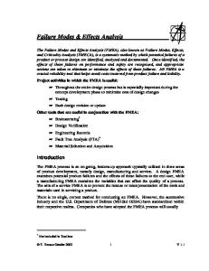
3 Product Description The 2051 is a pressure transmitter, or more accurately a series of pressure transmitters, utilizing either a capacitive (2051C) sensor in differential or gage modes or a resistive bridge (2051T) sensor in absolute or gage mode. The 2051C has dual interface diaphragms and can interface to a manifold. The 2051T has a single process connection. Both transmitters are microprocessor based and contain internal diagnostics as well as the ability to communicate via the HART digital protocol. For safety applications only the 4 to 20mA output is considered. Other outputs are not covered by this report.
Electronics Housing Press ure sens or
Multiplexer
PROM A/D
Meter Body
Microprocessor
D/A
Proportional 4 to 20 mA PV output
Digital I/O
FMEDA
Press ure
Figure 1 Parts included in the FMEDA - 2051 pressure transmitter
Table 5 gives an overview of the different versions that were considered in the FMEDA of the 2051. Table 5 Version Overview
2051C
Capacitive Sensor, Differential or Gage
2051T
Resistive Bridge Sensor, Absolute or Gage
The 2051 is classified as a Type B 4 device according to IEC 61508, having a hardware fault tolerance of 0.
4
Type B device: “Complex” component (using micro controllers or programmable logic); for details see 7.4.3.1.3 of IEC 61508-2. © exida Consulting LLC Rudolf Chalupa
Rosemount 07-10-08 FMEDA Report 2051 R001 V1 R1.doc Page 9 of 20
4 Failure Modes, Effects, and Diagnostic Analysis The Failure Modes, Effects, and Diagnostic Analysis was performed based on the documentation obtained from Rosemount and is documented in [R1] - [R6].
4.1
Failure Categories description
In order to judge the failure behavior of the 2051, the following definitions for the failure of the device were considered. Fail-Safe State
State where the output exceeds the user defined threshold
Fail Safe
Failure that causes the device to go to the defined fail-safe state without a demand from the process.
Fail Detected
Failure that causes the output signal to go to the predefined alarm state (>21.6 mA).
Fail Dangerous
Failure that deviates the measured input state or the actual output by more than 2% of span and that leaves the output within active scale
Fail Dangerous Undetected Failure that is dangerous and that is not being diagnosed by automatic diagnostics Fail Dangerous Detected
Failure that is dangerous but is detected by automatic diagnostics
Fail High
Failure that causes the output signal to go to the over-range or high alarm output current (>21.6mA)
Fail Low
Failure that causes the output signal to go to the under-range or low alarm output current( 99% of possible DU failures in the device. Table 10 Suggested Proof Test – 2051 Pressure Transmitter
Step
Action
1.
Bypass the safety function and take appropriate action to avoid a false trip
2.
Use HART communications to retrieve any diagnostics and take appropriate action.
3.
Send a HART command to the transmitter to go to the high alarm current output and verify that the analog current reaches that value8.
4.
Send a HART command to the transmitter to go to the low alarm current output and verify that the analog current reaches that value9.
5.
Perform a two-point calibration10 of the transmitter over the full working range.
6.
Remove the bypass and otherwise restore normal operation
8
This tests for compliance voltage problems such as a low loop power supply voltage or increased wiring resistance. This also tests for other possible failures.
9
This tests for possible quiescent current related failures.
10
If the two-point calibration is performed with electrical instrumentation, this proof test will not detect any failures of the sensor © exida Consulting LLC Rudolf Chalupa
Rosemount 07-10-08 FMEDA Report 2051 R001 V1 R1.doc Page 20 of 20