Fabrication and analysis of dielectric-elastomer minimum-energy structures for highly-deformable soft robotic systems Michael T. Petralia and Robert J. Wood Abstract— Dielectric-elastomer minimum-energy structures (DEMES) form an emerging class of soft robotic system. The appropriate materials and method for rapidly fabricating DEMES prototypes are described. A DEMES component suitable for use in highly-deformable soft robots is presented and analyzed. Combinations of this component into snake-like robots are also presented. A calculation for determining a DEMES’s maximum mechanical work, electromechanical efficiency, and energy density is described. The scope of the DEMES designspace and future research paths are discussed.
I. INTRODUCTION It is well-known that a dielectric elastomer film with stretchable surface electrodes—a dielectric elastomer actuator (DEA)—experiences an electrostatic pressure on its surfaces when an appropriate voltage (typically on the order of kV’s) is applied across the film’s thickness [1]. This pressure causes the film to contract in the thickness direction and expand its area. When stretched across a rigid frame, simple dielectric elastomer actuators (DEAs) have demonstrated areal strains greater than 380% [2], energy densities as high as 3.4 MJ/m3 [3], and maximum efficiencies up to 90% [4]. DEAs are of particular interest as electromechanical transducers because the transduction element is extremely pliant and highly extensible when compared to most other transducer technologies [5], [6]. As a result, DEAs are able to operate in systems that are entirely soft; moreover, DEAs have the ability to function as actively and passively deformable systems capable of large-scale changes in conformation (e.g. shape-shifting robots). Realizing this ability requires careful consideration of how the dielectric elastomer film interfaces with the other actuator components. Most all DEAs capable of undergoing large strains (>10%) and producing useful mechanical work do so by pretensioning the dielectric elastomer film against a spring element [7]–[9]. This process stores elastic energy in the spring that will be released when the film is activated. Unfortunately, the inherent soft characteristics of DEAs are underutilized because of the techniques typically used to hold the film in tension. Except in certain cases (e.g. when the spring is a fluid under pressure [10]), the spring element This work was supported by the Defense Sciences Office (DSO) of the Defense Advanced Research Projects Agency (DARPA) as part of the Chemical Robots (Chembots) project, Contract No. W911NF-08-C-0060. M. T. Petralia was supported by the Department of Defense (DoD) through a National Defense Science and Engineering Graduate (NDSEG) Fellowship. M. T. Petralia and R. J. Wood are with the School of Engineering and Applied Sciences, Harvard University, Cambridge, MA 02134, USA; and the Hansj¨org Wyss Institute for Biologically Inspired Engineering, Boston, MA 02115, USA.
[email protected];
[email protected]
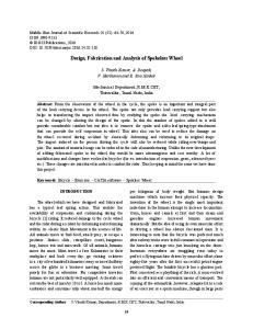
Fig. 1: Various inextensible, pliant planar frames adhered to 500%
isotropically stretched elastomer films. The films are F9473PC VHB transfer tape from 3M and the frames are cut from 76.2 µm thick ABS sheets. The object on the left of each 3D structure represents the original planar conformation of the frame. The bottommost object contains six of the triangular frames linked together along their edges.
generally cannot be considered soft; in situations where it can, the supporting frames used to hold the film in its pretensioned state are often constructed from a set of rigid spars that limit the possible conformations of the system [11]. In contrast, dielectric-elastomer minimum-energy structures (DEMES) are a subclass of DEAs where the spring element is an inextensible, pliant planar frame [12]. Since there are no rigid elements, DEMES are able to undergo large passive deformations in addition to actively changing shape. They are particularly interesting because not only do DEMES provide an actuation mechanism, but they can also function as the main structural elements in a soft robotic system.
To fabricate DEMES, a dielectric elastomer film is stretched and adhered to an inextensible, pliant frame. Because the frame can bend but not stretch, the transfer of elastic energy from the film to the frame causes the entire system to buckle. Figure 1 shows several examples of the myriad shapes that can be formed using only a simple planar frame and a isotropically stretched elastomer film. The final resting conformation of the film-frame system is a local or global minimum energy state [13]. By shifting the minimum energy state, DEMES achieve large-scale conformation changes. In order to generate this shift, the balance of stored energy in the system must be tipped by either adding or removing elastic energy from the system or changing the elastic properties of the components. The method for shifting minimum energy states in DEMES is applying electrostatic pressure to the film’s surfaces. This adds elastic energy to the film and results in the release of bending energy stored in the frame; in the limit, the frame returns to its original (typically planar) conformation. The work presented herein is broadly intended to demonstrate the potential of DEMES to function as soft robotic systems and more specifically to present material choices, fabrication methods and analysis techniques for rapidly prototyping and evaluating DEMES design concepts. Our ultimate goal is to explore the DEMES design space and choose the structures with the greatest potential for actuation and shape-shifting. Unfortunately, even for the most basic DEMES, predicting the parameters that produce the desired rest and actuated conformations is not straightforward; nor is it a simple task to calculate the actuation metrics: electromechanical efficiency, energy density, and bandwidth. In parallel to this work, we are developing a dynamic particle spring mesh model that predicts the 3D conformation of DEMES given an initial frame geometry and film pstretch. In this paper we first focus on the choice of materials and a method for rapidly fabricating DEMES prototypes respectively in §II and §III. Next we explain our experiments with the most basic DEMES design as well as experiments with a DEMES unit cell and present examples of how this unit cell can be incorporated into more complicated snakelike DEMES systems in §IV. We present a definition of the mechanical work output, the electromechanical efficiency, and the energy density for DEMES in §V. Finally we conclude with a look ahead at the future of DEMES indicating the scope of the design space and capacity of DEMES to function as soft robotic systems in §VI . II. MATERIALS SELECTION There have been many advances in DEA materials since the start of the field in the late 1990’s [14]–[17]. Here we are focused on shortening fabrication time rather than manufacturing long-lasting, optimized systems; we forgo using the state-of-the-art and instead opt for off-the-shelf materials wherever possible.
A. Dielectric elastomer film For the dielectric elastomer film we use F9473PC VHB transfer tape (0.26 mm thick) from 3M.∗ From our experience, VHB transfer tape is desirable for use in prototyping because of its ability to achieve high active strains, accept large stretches during manufacturing, and reliably produce actuation without failure. It is not appropriate for longterm use because VHB films suffer from stress relaxation and other issues that cause the actuation capabilities of the DEMES to degrade over several days and to eventually fail from dielectric breakdown. Though the precise mechanisms leading to this failure are not well understood at this time, we speculate that it is due in part to the relaxation of the polymer chains eliminating the stretch-induced enhancement in dielectric breakdown strength [18], [19]. Additionally, the VHB polymer network may, over time, swell with silicone oil and carbon particles from the carbon-grease electrodes (discussed below) increasing the likelihood of an electric pathway through the film. B. Stretchable electrodes For the stretchable electrodes we use conductive carbon grease from MG Chemicals.† The main advantage of the carbon grease is the ease of application. For the scale of DEMES discussed in this paper, the application time for the electrodes is on the order of five minutes. Short application times are important because we need to minimize the time the film is exposed to the air in order to prevent dust and debris from settling on the film surface and remaining between the dielectric film and the electrode (as will be discussed later). Though the carbon grease is easily applied, it remains wet after application. This creates a host of practical issues for fabricating and testing all but the simplest DEMES prototypes; the electrodes are prone to smearing which is generally messy, limits the ability to handle the devices, and most importantly, quickly lead to short circuits. Attempts at encapsulation were successful, but proved cumbersome and unreliable. Figure 2 shows a simple DEMES with carbon grease electrodes encapsulated in 0.05 mm thick F9460PC VHB transfer tape. It is clear that even though carbon grease is appropriate for the simple DEMES designs presented throughout this paper, when fabricating more elaborate designs with multiple DEMES linked together (e.g the snake-like robots described in §IV) different techniques for the application and encapsulation of the stretchable electrodes are necessary. One technique we have been experimenting with is the use of sputter-coated copper electrodes. Applying these thin-film metals after stretching the elastomer limits the failure mode of the electrodes to out-of-plane buckling. At this time, we have not successfully determined the system parameters (i.e. film and frame stiffness, electrode layer thickness, etc.) that will produce a functional DEMES. ∗ 3M, † MG
3M Center, St. Paul, MN 55144, USA. Chemicals Ltd, 9347 193 St., Surrey, BC V4N 4E7, Canada.
Fig. 4: A photograph of a complete ABS frame. Copper pads and Fig. 2: A circular DEMES with conductive carbon-grease electrodes encapsulated in 0.05 mm thick F9460PC VHB transfer tape.
Fig. 3: A diagram illustrating the main steps in the DEMES fabrication process.
lead wires can be seen at each of the triangle tips. Slightly visible is a Y- shaped frame stiffener adhered to the center cross members of the frame. Not visible are 50 µm layers of VHB transfer tape affixed to the underside of the frame and between the frame stiffener and the frame.
Fig. 5: The photographs on the left and right show the application of carbon grease through the polycoated paper mask onto the unstretched VHB film and the resulting alignment grid, respectively. The VHB film appears tan in these photographs because its paper liner is still attached.
C. Inextensible pliant frame For the frame we use 76.2 µm thick sheets of ABS plastic purchased from the McMaster-Carr Supply Company.‡ Though the yield strength of the ABS is not high enough to ensure robust systems immune to plastic deformation, the bending stiffness is well-matched to the stretching stiffness of the F9473PC VHB, the ABS sheets are easily cut with a laser-cutting system, and the ABS readily adheres to unstretched VHB transfer tape. III. FABRICATION PROCEDURE The main steps of our DEMES fabrication process are illustrated in Figure 3. To start, we construct the frame from a sheet of ABS plastic. A 50 µm layer of VHB transfer tape (F9460PC) adhered to the ABS sheet promotes bonding between the frame and the stretched VHB film. The frame is cut using a VersaLASER VLS 2.30 CO2 laser-cutting system from Universal Laser Systems.§ An additional layer of ABS is adhered in certain frame regions to make these areas stiffer and affect the final DEMES conformation. Magnet wires ‡ McMaster-Carr Supply Company, 200 Aurora Industrial Pkwy., Aurora, OH 44202, USA. § Universal Laser Systems, VersaLASER Division, 7845 E. Paradise Lane, Scottsdale, AZ 85260, USA.
soldered to copper pads are glued to the frame to act as electrical leads. Figure 4 shows a complete frame. Next we stretch the film. An alignment grid is deposited on a piece of unstretched VHB film, as shown in Figure 5, to indicate the degree and direction of stretch. The VersaLASER is used to cut the alignment-grid mask from a piece of the VHB tape backing: 58 lb polycoated Kraft paper liner. Polycoated paper does not adversely affect the VHB film surface; it is ideal for situations when interfacing with the film surface is required. Carbon grease is applied through the mask with a Superfine Microbrush from Microbrush International.¶ The carbon grease is effective in our situation not only because its effects on the film are negligable; more importantly, it was chosen because the artifacts of the carbongrease alignment grid are completely incorporated into the carbon-grease electrodes. When using a different stretchable electrode material, it should also be used for the alignment grid, if this is practicable. The VHB film is stretched by hand across a circular stretching frame in small radial increments, a number of which are shown in Figure 6. The film will adhere to ¶ Microbrush
USA.
International, 1376 Cheyenne Avenue, Grafton, WI 53024,
Fig. 6: The VHB film at various points in the stretching process.
The upper leftmost image shows the VHB film with the paper liner still attached. The bottom rightmost image shows the final stretched film at six-times stretch.
(a) Film support
(b) Film support and frame
Fig. 7: These photographs demonstrate the placement of the film
support and frame on the stretched film’s surface. The film support decreases the film area needed to hold the DEMES in tension during the fabrication process. Note that the frame shown is atypical in that it does not have any electrical lead wires.
the stretching frame within limits: VHB loses its adhesive properties both as it is handled and as it is stretched. The degree and direction of the stretch is monitored by comparing the deformed alignment grid to a transformed reference grid. For uniaxial, biaxial, and radial stretches (which provide constant stretch fields), this hand-stretching method is not the most effective; stretching apparatuses have been constructed for such tasks [11], [20], [21]. These devices increase the overall accuracy, precision, and repeatability of the stretching process; however, the process described above is still the most effective for arbitrary, non-constant stretch fields. A film support is attached to the areas of the film that will not be used, as shown in Figure 7a. These regions are important because they hold the DEMES in tension for the remainder of the fabrication process. Using a film support dramatically lowers the failure rate by decreasing the film area necessary to hold the DEMES in tension; preventing tears in the tensioned film from propagating; and allowing the DEMES to be released from the tensioned film without a parasitic build-up of VHB around the frame edge. The film support is cut with the VersaLaser from a sheet of VHB F9460PC with the polycoated Kraft paper liner still attached.
The frame is adhered on the remaining exposed section of the stretched film not covered by the film support, as shown in Figure 7b. An electrical lead wire soldered to a copper pad is glued to the film on the underside of the frame using Loctite 422,� a quick-setting cyanoacrylate adhesive. The carbongrease electrodes are generously painted on both sides of the stretched film with a Superfine Microbrush. Thin traces are painted onto the frame to connect the copper pads and the stretchable electrodes. A sharp knife is used to release the DEMES by cutting between the outside edge of the frame and the inside edge of the film support. It is important to note that maintaining a clean atmosphere, minimizing the film’s overall air-exposure time, and being vigilant when interfacing with the film’s surface are paramount. Any dust, debris, or defects on the film’s surface will lead to stress and charge concentration at that point causing the system to fail from either mechanical or dielectric breakdown, respectively. IV. EXPERIMENTAL RESULTS Theoretically, the simplest DEMES is the shell actuator described but never fabricated by Kofod et al. [13] where a uniaxially stretched dielectric elastomer film is made to span an inextensible pliant sheet such that the structure buckles into part of a cylinder. Upon actuation, the film is expected to extend its length, causing the frame to return to its planar state. The film width is assumed to remain constant during stretching (pure shear), the frame crosssection is approximated as the arc of a circle for small deflections, and the film is assumed to remain planar at all times; therefore, the stretching, bending, and electric energy contributions of the film, frame, and electrodes respectively can be determined analytically. Moreover, the geometric relationship between the film and frame is known a priori. Unfortunately, attempts at realizing and actuating Kofod’s theoretical structure proved unsuccessful for a number of practical reasons. First, Kofod’s pure shear assumption does not hold in reality, especially at the stretches (> 4) typically required for actuation. Second, even for high aspect ratio cylinders, where the length along the cylindrical axis is much greater than the diameter and the pure shear assumption is more appropriate, the art of fabrication proved to be awkward and cumbersome. Lastly, when a dielectric elastomer film is uniaxially stretched it tends to actuate in the direction perpendicular to the stretch direction [1], and thus even successfully fabricated shell actuators did not actuate as expected: It is more energetically favorable for the film to expand in the width direction, than for the film to extend further in its stretched direction, the frame to release its stored bending energy bringing the system to a planar state. As a note, we are not asserting that it is theoretically impossible to fabricate the shell actuator, but rather that difficulties and limitations in choosing the appropriate design parameters and in developing an efficient fabrication procedure outweigh the benefits of the simplified analytic analysis; � Henkel Consumer Adhesives, Inc., One Henkel Way, Rocky Hill, CT 06067, USA.
(a) Rest state
(b) Actuated state (1.2 kV)
Fig. 8: Two views of the DEMES Unit Cell in its rest and
actuated states. The ‘height’ changes from 15 mm to 3.5 mm upon application of 1.2 kV. (a) Rest conformation
moreover, our aim is to develop techniques and analyses that extend to a broad range of DEMES. To this end, we utilize the fabrication technique described in §III and construct a DEMES that mimicks the desirable actuation properties of the shell actuator as seen in see Figure 8. We refer to this device as the DEMES Unit Cell because of its ability to be joined together to form more complicated DEMES structures. The DEMES Unit Cell exceeds the theorized capabilities of the shell actuator because it actuates from half of a cylinder to nearly flat without a spanning film across the interior region of the device (i.e. the device interior remains empty and free to carry a payload). Figure 8 shows two views of the DEMES Unit Cell in its rest and actuated states. The VHB film in the DEMES Unit Cell is isotropically stretched to six times its length and width for a 36-times increase in film area. The length and width of the frame are respectively 40 and 18 mm; the width of the frame edges are 2.5 mm. The 1.2 kV actuation voltage is applied with a Bertan 605C-200P High Voltage Module from Spellman High Voltage Electronics.∗∗ The DEMES Unit Cell decreases its height 4.3-times while increasing its length 1.6-times. The blocked force of one half of the DEMES Unit Cell obtained by holding the center and measuring the force at rectangular tabs is 8 mN as recorded with a CS200 Compact Scale from Ohaus.†† Without any additional electronic elements, the actuation and relaxation times are 0.1 s and 4 s, respectively; the operation bandwidth (i.e. the frequency of cycling between the rest state and the actuated state) is 0.25 Hz. The potential of the DEMES Unit Cell to function as both an actuator and a shape-shifting structural network is illustrated by two robotic systems comprised solely of DEMES Unit Cells. The DEMES Ring shown in Figure 9 ∗∗ Spellman High Voltage Corporation, 475 Wireless Blvd., Hauppauge, NY 11788, USA. †† Ohaus Corporation, 19A Chapin Rd., P.O. Box 2033, Pine Brook, NJ 07058, USA.
(b) Actuated conformation (1.2 kV)
Fig. 9: Two views of the DEMES Ring in its rest and actuated conformations. The ring is comprised of two DEMES Unit Cells. Actuation voltage: 1.2 kV.
is comprised of two DEMES Unit Cells. The DEMES Ring experiences a 1.3-times decrease in height and a 1.8-times increase in length upon application of 1.2 kV. Connecting several DEMES Rings at the joints will result in a multisegmented robot capable of inchworm-like motion. The DEMES Serpentine shown in Figure 10 is constructed from five DEMES Unit Cells and contains ten individually controllable active regions (two per cell). It experiences a 1.7-times increase in length and a 1.4-times decrease in height upon application of 1.2 kV to all ten segments. V. ANALYSIS TECHNIQUES In the previous section experimental results for the blocked force, response time, and actuated strains were presented for the DEMES Unit Cell. Here we explicate a method for estimating the mechanical work, the electro-mechanical efficiency, and the energy density of a DEMES and find these values for the DEMES Unit Cell. First, consider the three elements that store and release energy in any DEMES system: the dielectric elastomer film; the inextensible pliant frame; and the stretchable electrodes. Stretching energy is added to the film and transferred to the frame as bending energy during fabrication. Upon actuation (i.e. application of a voltage) electric energy is added to the stretchable electrodes and promptly transferred to the film as additional stretching energy. In properly tuned systems, the areal expansion of the film leads to the release of the bending energy stored in the frame. Because the film’s areal expansion does not interact with the world directly, the only useful mechanical work from the DEMES must come from the bending energy released by the frame; therefore, the upper limit on the mechanical work from a DEMES is the total bending energy stored in the frame during fabrication.
(a) Rest conformation
(b) Actuated conformation (1.2 kV)
Fig. 10: Two views of the DEMES Serpentine in its rest and actuated conformations. The serpentine is comprised of 5 DEMES Unit Cells with ten individually controllable active regions. Actuation voltage: 1.2 kV.
Despite generally being outside of the small deflection regime, as a first order approximation of this stored bending energy, we follow Timoshenko’s [22] calculation of the strain energy in a plate subject to pure bending. We discretize the DEMES frame and consider the principal curvatures for each small region. In the coordinates of the principal planes of curvature, the twisting moments are exactly zero and we can write the bending energy for each element Ui as � 2 � 1 2 Ui = DAi ∆κ1,i + ∆κ2,i + 2ν∆κ1,i ∆κ2,i (1) 2 � � where D = Eh3 /12 1 − ν 2 is the flexural rigidity, E is the modulus of elasticity, h is the thickness, ν is the Poisson’s ratio, Ai is the elemental area, and ∆κn,i is the change in curvature of the ith element along the principle direction n. The sum of these energies over all m of the DEMES frame elements provides an estimate to the maximum mechanical work Wm that the DEMES can produce: m
Wm = ∑ Ui .
(2)
i=1
It is straightforward then to calculate the maximum energy density as the mechanical work divided by either the mass or volume of the DEMES. Since the only mechanical energy out is the bending energy and the only input energy is the electric energy on the compliant capacitor, we define the maximum electromechanical efficiency as ηmax =
Um Ucap
(3)
where Ucap = 12 CΦ2 is the electric energy stored on the compliant capacitor, C is the capacitance, and Φ is the applied voltage. Here we must assume a uniform charge density on the electrodes, a homogeneous electric field between the electrodes, and the electrodes to be parallel. A first order approximation of these values for the DEMES Unit Cell is obtained by considering a square frame that bends into the arc of a circle.
TABLE I: DEMES Unit Cell parameters E A h ν r C Φ V∗ V∗
Young’s modulus of frame Surface area of frame Frame thickness Poisson’s ratio of frame Radius of arc Capacitance Voltage Volume of actuator Mass of actuator
2.3 GPa 60 mm2 76.2 µm 0.5 0.5 cm 0.333 nF 1.2 kV 10 mm3 70 mg
Using the values in Table I, the maximum mechanical work output was 18 mJ, the energy density was 18 kJ/m3 or 2.5 mJ/g, and the electromechanical efficiency was 75%. VI. CONCLUSIONS In this paper we presented materials and methods for rapidly fabricating DEMES. Using these, we fabricated and analyzed a DEMES Unit Cell and two robotic systems comprised of multiple cells. A method for determining the maximum mechanical work output along with the energy density and electromechanical efficiency was also presented. Here we would like to point to future DEMES research. As mentioned, we are working on a dynamic particle spring mesh model to help predict the minimum energy states. This software will enable evaluation of DEMES designs without the need to devise a fabrication method. Not limited by what is easy to fabricate, we can begin to think about each of the elements in a DEMES and how they can be made to actively change; anything that changes the balance of stored energy in the system will result in a conformation change. In this paper we limited ourselves to initial planar states, only changing the geometry of the film, and homogenous frame properties. More complicated structures could be formed by incorporating non-planar initial structures, frames and films with spatially varying mechanical properties, and frames with active regions. Joining together various DEMES along their edges, allows even more complicated structures to be formed.
We are just scratching the surface of the DEMES design space. Moreover, the capacity for DEMES to functions as shape-shifting robots is widely unexplored. We hope that this paper will convince researchers of the value of DEMES and spur interest in the field. VII. ACKNOWLEDGEMENTS The authors would like to thank Dr. Sangbae Kim for helpful discussions that lead to the use of the frame stiffener in the fabrication process. The authors would like to acknowledge Asher Bartch for his help fabricating the DEMES shell actuators and operating the 3D scanning system. R EFERENCES [1] R. Pelrine, R. Kornbluh, Q. Pei, and J. Joseph. High-speed electrically actuated elastomers with strain greater than 100%. Science, 287(5454):836–839, 2000. [2] R. Kornbluh, R. Pelrine, and Q. Pei. Dielectric elastomer produces strain of 380%. EAP Newsletter, 2(2):10–11, 2002. [3] R. Kornbluh and R. Pelrine. High-performance acrylic and silicone elastomers. In F. Carpi, D. De Rossi, R. Kornbluh, R. Pelrine, and P. Sommer-Larsen, editors, Dielectric elastomers as electromechanical transducers: Fundamentals, materials, devices, models and applications of an emerging electroactive polymer technology, chapter 4. Elsevier, 2008. [4] R. Pelrine, R. Kornbluh, J. Joseph, R. Heydt, Q. Pei, and S. Chiba. High-field deformation of elastomeric dielectrics for actuators. Materials Science & Engineering C, 11(2):89–100, 2000. [5] I. Hunter, J. Hollerbach, and J. Ballantyne. A comparative analysis of actuator technologies for robotics. Robotics Review, 2, 1992. [6] J. Madden, N. Vandesteeg, P. Anquetil, P. Madden, A. Takshi, R. Pytel, S. Lafontaine, P. Wieringa, , and I. Hunter. Artificial muscle technology: Physical principles and naval prospects. IEEE Journal of Oceanic Engineering, 29:706–727, 2004. [7] R. Kornbluh. Fundamental configurations for dielectric elastomer actuators. In F. Carpi, D. De Rossi, R. Kornbluh, R. Pelrine, and P. Sommer-Larsen, editors, Dielectric elastomers as electromechanical transducers: Fundamentals, materials, devices, models and applications of an emerging electroactive polymer technology, chapter 8. Elsevier, 2008. [8] J. Plante and S. Dubowsky. On the properties of dielectric elastomer actuators and their design implications. Smart Materials and Structures, 16:S227–S236, 2007. [9] M. Rosentahl and Q. Pei. Multiple-degrees-of-freedom roll actuators. In F. Carpi, D. De Rossi, R. Kornbluh, R. Pelrine, and P. SommerLarsen, editors, Dielectric elastomers as electromechanical transducers: Fundamentals, materials, devices, models and applications of an emerging electroactive polymer technology, chapter 9. Elsevier, 2008. [10] F. Carpi, G. Frediani, S. Tarantino, and D. De Rossi. Millimetrescale bubble-like dielectric elastomer actuators. Polymer International, 59(3):407–414, 2010. [11] J. Plante. Dielectric elastomer actuators for binary robotics and mechatronics. PhD thesis, Massachusetts Institute of Technology, 2006. [12] G. Kofod, M. Paajanen, and S. Bauer. Self-organized minimumenergy structures for dielectric elastomer actuators. Applied Physics A: Materials Science & Processing, 85(2):141–143, 2006. [13] G. Kofod, W. Wirges, M. Paajanen, and S. Bauer. Energy minimization for self-organized structure formation and actuation. Applied Physics Letters, 90:081916, 2007. [14] F. Carpi, P. Chiarelli, A. Mazzoldi, and D. De Rossi. Electromechanical characterisation of dielectric elastomer planar actuators: comparative evaluation of different electrode materials and different counterloads. Sensors & Actuators: A. Physical, 107(1):85–95, 2003. [15] M.Y. Benslimane, H.E. Kiil, and M.J. Tryson. Dielectric electroactive polymer push actuators: performance and challenges. Polymer International, 59(3):415–412, 2010. [16] G. Gallone, F. Galantini, and F. Carpi. Perspectives for new dielectric elastomers with improved electromechanical actuation performance: Composites versus blends. Polymer International, 59(3):400–406, 2010.
[17] H. Zhang, L. D¨uring, G. Kovacs, W. Yuan, X. Niu, and Q. Pei. Interpenetrating polymer networks based on acrylic elastomers and plasticizers with improved actuation temperature range. Polymer International, 59(3):384–390, 2010. [18] G. Kofod, P. Sommer-Larsen, R. Kornbluh, and R. Pelrine. Actuation response of polyacrylate dielectric elastomers. Journal of Intelligent Material Systems and Structures, 14(12):787, 2003. [19] J. Plante and S. Dubowsky. Large-scale failure modes of dielectric elastomer actuators. International Journal of Solids and Structures, 43(25-26):7727–7751, 2006. [20] H.C. Ko, M.P. Stoykovich, J. Song, V. Malyarchuk, W.M. Choi, C.J. Yu, J.B. Geddes Iii, J. Xiao, S. Wang, Y. Huang, et al. A hemispherical electronic eye camera based on compressible silicon optoelectronics (Supplementary Information). Nature, 454(7205):748–753, 2008. [21] P. Lochmatter and G. Kovacs. Design and characterization of an active hinge segment based on soft dielectric EAPs. Sensors and Actuators A: Physical, 141(2):577–587, 2008. [22] S. Timoshenko and S. Woinowsky-Krieger. Theory of Plates and Shells. McGraw-Hill Book Company, 2nd edition, 1959.