EE 418 Final Project Front End of Software Defined Radios Zheng Luo Instructor: Mani Mina
I. Abstract A software defined radio (SDR) is a radio which its hardware has been typically implemented to be able to receive and transmit different radio protocols. The certain frequency band which should be used at a time is determined by the embedded system. Thus, the software defined radio can be used in different cases by changing the embedded system instead of modifying the hardware. Typically, a software defined radio contains following components: - RF Front End: the transmitting and receiving part including the antenna, filters, switches, baluns and synthesizers with phase locked loops (PLL). - ADC Module: for converting messages between analog and digital signals in the baseband (typically there are both I/Q signals). - FPGA Module: for programming controlling the whole system (USB modules may be included as the interface). The RF front end can be made to work at a wide frequency range, but generally it is used at a high frequency range since most of wireless signals are transmitting at the so called radio frequency (RF). Based on its abilities, software defined radios are widely used. For example, cellphones, especially smart phones, are using SDRs in order to receive signals that are based on different standards. In this project, the analysis of the RF front end of SDRs will base on an open source project called HackRF [1] because this project is currently building a highly qualified SDR and have an excellent implementation at present. The circuit is able to work at a very wide range of frequency so that it is a good example to analyze radios in different cases of frequency. In addition, this paper will also conduct a comparison between ham radios and SDRs in order to have a view of the difference and developing of radios.
II. Open Source Project: HackRF The project HackRF which aimed to build a qualified cheap software-defined radio started in
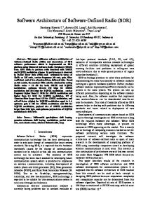
2012. It is open for every person; and now the product is under testing. The goals for this project [1] are: - Transmit and Receive at Frequency from 100MHz to 6GHz - Maximum Sample Rate: 20Msps - Resolution: 8 Bits - Interface: High Speed USB - Power Supply: USB Bus Power - Portable - Open Source Hardware and Software - Low Cost The designed circuits of the project are PCB designs. By looking at those circuits, the following sketch can be drawn to describe the whole system:
The radio system is a half-duplex circuit which means that it can only transmit or receive signals at a time. In this sketch, the names labeled on different places are just used in the project to identify different components since the project is separated to three parts and each part has several design plans. Eventually, the three designs used are combined as above. In
the structure diagram above, the RF front end includes the antenna, synthesizer, amplifier, and transceiver.
III. RF Front End The front end has two stages: one is the transceiver (2.3 to 2.7 GHz); another is the synthesizer (30 MHz to 6 GHz). Although it is able to work at low frequency or intermediate frequency range, the structure is built by considering the high frequency. Because the message contains both I/Q signals, it is hard to synthesize and add them together to the high frequency range at a time. Thus, for working in high frequency, an extra synthesizer is used in the front end to raise the carrier frequency of the transmitting signals or lower down that of the received signals. In the front end, the used synthesizer is RFFC5072 which has only one mixer. For a half-duplex system, this would be more efficient than using RFFC5071 which has two mixers (a former design used RFFC5071). However, a more complex structure comes out. In order to make sure that both receiving and transmitting paths can go through the synthesizer, switches are used. Those switches are controlled by the complex programmable logic device (CPLD) since the CPLD is good enough to do this and can lower down the load of the FPGA (microcontroller). The same situation is applied to the amplifier. There is an amplitude detector in the transceiver MAX2837. It can detect the signal amplitude and send the information to the microcontroller to decide how much the signal should be amplified or whether the signal should go through the amplifier (switches are used). Except those main components, many basic circuit units (capacitors and inductors) are used on the PCB to handle the high-speed characteristics of the circuit board: 1. For the DC voltage supply, Vcc and the ground are connected through three pairs of capacitors where each pair includes a 33 pF and a 10 nF capacitors to decrease the AC component. In fact, this is a compensation for the high-frequency noise introduced by transmission lines. In this case, the reason why two capacitors are used as a pair is that the
actual amplitude-frequency response of a capacitor in high frequency has a “U” shape. 2. In other places, capacitors and inductors are also widely used for DC block or AC block, or they essentially work as simple filters for handling the high-frequency characteristics. However, for radio signals, other packaged low-pass and high-pass filter units are used because simple filters are not enough. Transmitting signals are filtered and then go through baluns (inverse for received signals). For the bypass path, there is only a band-pass balun since this signal goes out directly from the transceiver and will not go through the synthesizer named RFFC5072.
IV. Comparison to Ham Radios Ham radios are used for people whose hobbies are building radios or using radios to test or communicate. In this paper, the point is to compare the technique of ham radios with it of software defined radios other than the number of stations or the distribution. Actually, software defined radios are originally from software radios. The so called software radio is required to be able to work at a very wide frequency band and catch and process all of the signals at the whole frequency band it uses. Thus, it doesn’t need people to rewrite the embedded system once the product is done. However, while the frequency range is very wide, the hardware (processor) cannot even handle all of signals. Also, this method is not efficient since a lot of signals are not needed at a time. That is the reason why the software defined radio is developed. On the other hand, the ham radio only works at a narrow and relatively low frequency range and uses call numbers to choose the channel. In this case, the ham radio can be thought as the basic idea of the software radio, but will not meet the problem that comes from software radio. In fact, a ham radio can be made as a software-defined radio; but this is exactly not efficient, or even ridiculous. However, for more advanced usage, software defined radios are much better and more professional.
V. Conclusion
The RF front end is a main part in radio designs since it is responsible for communications of signals. For a software defined radio which must be able to work at high frequency, designers have to consider the high-speed characteristics of all of components so that it would be a time consuming work. By analyzing this open source project, it is able to obtain a great experience of how to design a PCB board which is a high speed system. For the future work, I plan to design a WiFi modem which can be also considered a software defined radio but should be easier to implement than the HackRF. Except the PCB design, I must also look at the IEEE 802.11 standard which defines radio technique. This is planned to be done during the coming winter break.
VI. Appendix The following three circuits are called licorice, lemondrop, and jellybean respectively [1]. They are analyzed in this paper. As shown in the design sketch, only these three circuits are used eventually for the project HackRF. For other designed circuits, it is able to download the design files and open it using the tool called KiCad.
VII. Reference [1] Great Scott Gadgets: HackRF. 2012. Web.