Earth Fault Current in Medium-Voltage Networks with Resonant Earthing of the Neutral Point
Preface The most common faults occurring in medium-voltage networks are single-pole earth faults. If such networks are operated with a system using resonant grounding at the neutral point, this method, besides providing the customer with uninterrupted electricity despite an earth fault, brings with it other advantages, such as low fault currents, an automatic arcextinguishing circuit and generally improved profitability. It is, however, from a human safety point of view (which requires touch potential to be kept within approved limits), an absolute necessity in all cases to limit the residual earth fault current to predetermined values. The factors influencing the amount of residual earth fault current are the earth fault current itself, the detuning, the attenuation and the element due to harmonics, which has, to date, been impossible to calculate with sufficient accuracy. Any attempt to determine it by measurement is costly in time and trouble, is risky and is of limited usability in planning for future projects. There is now a computation program with the name BOSES, which provides a sufficiently accurate predictive calculation of the residual earth fault current and thus ensures safer planning, saves time and offers the possibility of prognostication in decision-making at the planning stage of grids and networks. Essential to limit residual earth fault currents The majority of public medium voltage networks in Germany operate on the basis of “RESPE”, which stands for resonant earthing of the neutral point. As is well known, this method ensures that the capacitive 50-Hz-component of the fault current ICE (this is the residual earth fault current) in situations of single-pole earth faults is largely compensated by the inductive current ID of a modifiable earth current choke at the neutral-point of the supplying transformer(s) (Fig. 1).
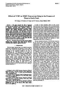
Fig. 1: Earth fault in Line 1 a) simplified network b) equivalent zero system circuit
1
The residual current Ir at the fault point is described by the equation:
Ir = ICE
2 v 2 + d2 + irOS
(1)
where the fault current ICE = 3 UN ωCE (this is the 50 Hz value). These are the meanings of the symbols in equation (1): v = 1 − ID ICE detuning (50 Hz value)
d = I Wr ICE irOS = IrOS ICE
attenuation, IWr: effective residual current (50 Hz value) harmonic current in relation to ICE.
If the grid operator wishes to make use of the advantages of RESPE, which are, among others, § that it is possible to continue to operate the grid even with frequent single-pole earth faults, more or less guaranteeing uninterrupted electricity supply to the mains users (as is also written large in the regulatory instruments), § that the short circuit arc goes out automatically (this applies mainly to overhead lines), § that single-pole faults are not extended into double earth faults or short circuits, § that there will only be a slight influence on neighbouring wires if an earth fault occurs, and § that the earthing arrangements will be relatively easy and cheap to install, then it is necessary to ensure that the residual current Ir is limited to values below 60 A, so that the touch potential laid down as UTp ≤ 75 V in DIN VDE 0101 [1] is not exceeded. Limiting residual earth fault current means reducing harmonic current As technology has developed over recent years, networks have been extended and the amount of cable in medium voltage networks around a transforming station has increased. This means that short circuit currents ICE between 700 A and 900 A are no longer unusual and have even exceeded 1000 A. The detuning level may be reduced to between 0 % and 2 % in networks with a large amount of cable. The use of good cable symmetry will result in only smallish displacement voltages. It is not possible to have any influence on attenuation relationships. These are determined by the losses in the various electrical equipments (the choke, the cable or wires, the transformer). Where there is a high proportion of cable in the network, it must be assumed that the attenuation values will be between d = 2 % and d = 4 %. In electrical overhead grids, it is also possible for much higher values to occur because of the weather. The network operator is similarly unable directly to affect the harmonic portion IRES,H in the residual current, which is determined directly by the distortion in the supply voltage. Even when the limits for the level of harmonics in the supply voltage are kept within those given in DIN EN 50160 [2], the residual current may exceed the 60-A limit. The permissible harmonic residual current to be drawn, IRES,H_permit, is immediately derived from Equation (1):
iRES , H _ permit ≤
(I r
I CE ) − v 2 − d 2 where Ir_permit = 60 A 2
(2)
In a situation where ν = 2 %, d = 4 % and ICE = 800 A, the harmonic current in the residual earth fault current should be limited to values of 6 % (i.e. 48 A). The author’s own
2
investigations [3] and measurements [4] indicate that even in the case of a voltage distortion caused by the 5th harmonic of uh=5 = 3 % to uh=5 = 4 %, harmonic currents greater than 48 A are found. There are basically two routes which can be taken towards a decision on which networks require measures to limit the harmonic current element in the residual earth fault current: 1st method: Systematic but difficult and costly measurements of the earth fault current 2nd method: To use a computer program for predictive calculation of the harmonic portion IRES,H in the residual current and from this to discover which networks are “critical” from the point of view of earth fault current. In the case here considered, the second method was used for reasons § of cost, § of risk reduction (avoidance of danger of a double earth fault / short circuit) § of savings in time and § of the need for prognostication in grid planning. This second method was backed up by earth fault measurements. Systematisation of the network structure plus analysis of the harmonic relations required for predictive calculation of IRES,H Public electricity grids in the medium voltage range are, on the whole, structured similarly and it tends to be the 5th harmonic which dominates in the supply. Figure 2 shows the basic structure of most grids.
Fig 2: Basic structure of the network
The electricity supply for 20 kV networks of more or less similar form is provided from a 110 kV grid in a transforming station with two transformers providing rated power of (for instance) SrT = 31,5 MVA and relative short circuit voltage uk = 12 %. The switcher in the distribution station with its single, compact bus bar and longitudinal coupling permit either single transformer operation (in which case one transformer supplies all the cable or overhead line outputs on the 20 kV side) or dual transformer operation (whereby each transformer supplies one part of a 20 kV network). On average there are between eight and ten line outputs that
3
supply the domestic grid stations (for households) and trade and industry in a branched distribution network with electricity. The network can be operated as a stub line or as an open or closed circle. The voltage distortion in the 20-kV networks results from two factors: consumer behaviour on whichever network is affected, and the sum of loads on the 110-kV grid arising from all the medium voltage networks supplied by that grid. In occasional cases there may be distorting loads in the high voltage grid which also determine the prior load on this grid. Figure 3 shows the characteristic voltage distortion of a 20-kV network over time.
Fig. 3: Distorted supply voltage in a 20 kV public network
The total harmonic distortion of the supply voltage (THD U) is very much determined by the 5th harmonic uh=5 and is highest at the weekend and in the evenings. However, the 3rd and the 7th harmonics can also contribute a portion of the THD U. While the 3rd harmonic is in physical terms an asymmetrical 3-phase system (composed of the symmetrical components), the 5th and the 7th harmonics are largely symmetrical 3-phase systems (7th harmonic: a positive rotating system; 5th harmonic: a negative rotating system). In the 20-kV networks, the total harmonic voltage distortion THD U ≈ uh=5 is frequently higher than 4 % and in certain cases (of urban electricity supply) is already exceeding the levels permitted under EN 50160 [2]. In this connection it is important to note that compensatory waves when there is an earth fault have a frequency of several hundred Hertz, which shows that resonance phenomena in the range of the 3rd to the 5th harmonics are not to be dismissed as a possibility in a network suffering earth faults. Resonance can lead to a rise in residual current when a fault occurs, and this is not exclusively associated with medium voltage networks with high short-circuit currents (ICE > 700 A). Predictive calculation of the harmonic component in the residual current IRES,H rendered difficult by the wide variety in 20-kV networks Although networks are basically well structured in the 110 kV / 20 kV range (cf. Fig. 1), the highly variable configuration of the 20-kV network – length, cross-section, type of wiring at the outputs – makes it well-nigh impossible to calculate in advance the exact harmonic component in the residual current.
4
A digital computation program, BOSES, has been devised with a highly simplified network of representative circuits at its core. It is intended to capture the physical relations for short circuit calculation in the harmonic range and to compute representative values on the basis of operational supply data from the grid, the structure of the grid and the load on the grid. From Equation (1) the frequencies above 150 Hz (h = 3) and UN >> Uh can be directly derived: 2 2 2 iRES , H >> v + d
(3)
and thus almost the whole of the higher-frequency share of the residual current flows exclusively through the fault point. The detuning
v = 1 − I D I CE ⋅ h −2 ≈ 1 − 1 h 2
(4)
assumes values approximating to 1. There is only a small harmonic current flowing in the choke current. The harmonic current places a bisymmetrical load on the transformer and the high-voltage supply grid, so that loops arise for the current flow in the power line network.
Fig. 4: Simplified equivalent circuit for calculation of the harmonics in the residual earth fault current
The representative circuit in Figure 4 for the harmonic range is derived from Figure 1 and in principle makes calculation of harmonic residual currents for h = 3, 5 and 7 possible.
I rh =
(3 X
3Uh
− X C ers h ) + R 2
L ers h
2 ers h
(5)
⋅9
Now the total harmonic residual current is calculable:
I RES , H =
∑I
2 rh
(6)
h
(
)
In Equation (5) the elements 3 X L ers h − X C ers h can be interpreted as detuning (νOS h), and Rers h can be interpreted as attenuation (dOS h) of the frequency h.
5
Computer assisted calculation of harmonics in residual earth fault currents The Software BOSES offer a fast and adequate calculation of harmonics in residual earth fault currents. While
X C ers h =
3 UN ICE ⋅ h
(7)
is relatively simple to work out, the calculation of Lersh and Rersh requires not only knowledge of the network structure as in Figure 2 but also time-consuming network calculations and an examination of the electrical operating data.
Fig. 5: Entering the network data into BOSES
The representative resistance and reactance figures mentioned above are computed with BOSES on the basis of Figure 5: § minimum short circuit power in the 110-kV grid, § electrical operating data taking into account their frequency dependency, § the load on the grid, § the power-line structure in the MV area and § the practical network operation (characterised by its use of transformers, its detuning v and its attenuation d) and from these Irh or Ir are calculated.
Table 1: Comparison of calculated and measured values
6
Summary and Prospects Working out the answer to Equation (5) using BOSES gave important information of relevance to predictive calculation of residual earth fault current: It is possible for the detuning νOSh to assume the value of zero (RESONANCE) in dependence on ICE and h. The harmonic element of the residual current is then solely limited by the attenuation dOSh! In detail found out:
As the dominant harmonic in the short circuit current is the 5th, relatively high residual currents are to be expected in the harmonic range if the networks are small (ICE in the range 150 A to 200 A). Urban supply areas with high distortion in the supply voltage and a heavy load on the grid (meaning low attenuation) must be looked at with a particularly critical eye and note should be taken of DUAL-TRANSFORMER OPERATION. In very wide networks (ICE > 1000 A), XC ers h is >> XL ers h. It follows that the portion of harmonics in the residual earth fault current is smaller in these networks. Initial comparison of the outcomes of calculation and of measurements (Table 1) reveals acceptable agreement between the two methods, confirming that a decision based on computation (of which grids require measures to limit the residual earth current) will be a safe decision. Huge savings in the time and trouble associated with direct measurements will result. Such measurements will be necessary in future only in borderline cases and possibly in the preparatory stages of remedial treatment (where the Ir is calculated as falling in the range 60 A to 70 A). To reduce the residual earth fault current in any situation there are various technical solutions. Which one to use must be decided on the basis of expert computation, of which the reliability is now assured, and on an evaluation of the costs involved. Those in question include: o power-line connections between transforming stations on the 20-kV side, o extension of existing transforming stations by adding a third transformer or replacement of existing transformers with three-winding transformers, o construction of new transforming stations, o conversion of the neutral-point management for a 20-kV network to a lowresistance neutral point earthing and o reduction of the residual earth fault current by compensation, which will be covered in another article. In this article, the author has reported a selection of investigative results to which staff of the following companies have made major contributions: E.On edis Netz GmbH (contact person, Stefan Dorendorf, tel. +49 (0)3361 702744, email
[email protected]), KEMA IEV Dresden, H. Kleinknecht GmbH & Co. KG Ilmenau.
7
Bibliography [1]
DIN VDE 0101: 2000-01 Starkstromanlagen mit Nennwechselspannung über 1 kV. Berlin – Offenbach: VDE Verlag
[2]
DIN EN 50160:2000-03 Merkmale der Spannung in öffentlichen Elektrizitätsversorgungsnetzen. Berlin - Beuth
[3]
Stade, Dietrich; Schau, Holger Influence of voltage harmonics on single-phase earth fault currents First International Conference „Power Quality“ Paris 15.10. – 18.10.1991 Session D2: Network-based quality improvements Report D-24
[4]
Eckhard Brand; Alexander Montebaur; Jan Schwarz Bestimmung des Erdschlussreststroms mittels Spannungsqualität im MS-Netz etz journal, issue 8/2006, p. 38 - 41
8
Symbols:
h I Ih ih ICE Ir IrW Irh irh IRES,H iRES,H ID I0
harmonic index (for the frequency relation: h = fH/50 Hz) current (effective value) current of the harmonic h (effective value) current of the harmonic h (power unit value, percentage value) capacitive earth fault current (effective value) residual earth fault current (effective value) residual earth fault current (effective value) residual earth fault current of the harmonic h (effective value) residual earth fault current of the harmonic h (p.u. value, percentage value) harmonic share of the residual earth fault current (effective value) harmonic share of the residual earth fault current (p.u. value, related to ICE) choke current (effective value) zero current
U Uh uh UN uk UTp U0 RD (R0D) XD (X0D) X0T X0L Rersh XLersh XCersh SrT Sk THD U THD I ν νOS h d dOS h fH
voltage (effective value) voltage of the harmonic h (effective value) voltage of the harmonic h (power unit value, percentage value) nominal network voltage short circuit voltage (power unit value, percentage value) touch potential zero voltage resistance of the choke (from zero upwards) reactance of the choke (from zero upwards) zero reactance (transformer) zero reactance (power line) representative resistance at frequency h representative resistance (ind.) at frequency h representative resistance (cap.) at frequency h rated power (transformer) short-circuit power (minimum) voltage distortion factor (power unit value, % value) current distortion factor (power unit value, % value) detuning (50 Hz value) detuning at frequency h attenuation (50 Hz value) attenuation at frequency h frequency of the harmonic h
9