2007 Hummer H3 2007 STEERING Steering Wheel and Column - H3
2007 STEERING Steering Wheel and Column - H3
SPECIFICATIONS FASTENER TIGHTENING SPECIFICATIONS
Fastener Tightening Specifications Application Lower Intermediate Steering Shaft Bolt Lower Steering Column Trim Cover Bolt Multifunction Turn Signal Switch Housing Bolt Steering Column Bolt Steering Column Nut Steering Wheel Nut Tilt Lever Bolt Turn Signal Multifunction Switch Bolt Upper Intermediate Steering Shaft Bolt (at the lower intermediate steering shaft) Upper Intermediate Steering Shaft Bolt (at the steering gear)
Specification Metric English 45 N.m 33 lb ft 3.5 N.m 31 lb in 2.5 N.m 22 lb in 25 N.m 18 lb ft 30 N.m 22 lb ft 35 N.m 26 lb ft 1 N.m 9 lb in 4.5 N.m 40 lb in 23 N.m
17 lb ft
62 N.m
46 lb ft
COMPONENT LOCATOR STEERING COLUMN DISASSEMBLED VIEW
MY Sunday, March 29, 2009 9:32:41 9:32:35 PM
Page 1
© 2005 Mitchell Repair Information Company, LLC.
2007 Hummer H3 2007 STEERING Steering Wheel and Column - H3
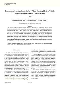
Fig. 1: Steering Column Component View - Floor Shift Tilt Courtesy of GENERAL MOTORS CORP. Callouts For Fig. 1 Callout Component Name 1 Upper Trim Cover 2 Lower Trim Cover 3 Shoulder Tapping Screws 4 Pan Head Tapping Screws 5 Multifunction Switch Assembly MY Sunday, March 29, 2009 9:32:35 PM
Page 2
© 2005 Mitchell Repair Information Company, LLC.
2007 Hummer H3 2007 STEERING Steering Wheel and Column - H3
6 7 8 9 10 11 12 13 14 15 16 17 18 19 20 21 22 23 23 24 25 26 27 28 29 30 31
Washer Head Screws Switch Mounting Plate Bearing Retainer Spring Retainer Upper Bearing Spring Inner Race Seat Steering Column Housing Assembly Ignition Switch and Lock Housing Assembly Set Screws Release Lever Pin Lever Spring Assembly Release Lever Spring Spring Guide Tilt Spring Steering Shaft Assembly Torque Head Screws Tilt Bumper Pivot Pin Pivot Pins Steering Column Support Assembly Bracket and Upper Jacket Assembly Lower Column Support Bracket Lower Bracket Retainer Spacer Washer and Bolt Assembly Lower Shaft Bearing Assembly Bolt and Retainer Assembly Intermediate Steering Shaft Assembly
DIAGNOSTIC INFORMATION AND PROCEDURES DIAGNOSTIC STARTING POINT - STEERING COLUMN
Begin the system diagnosis by reviewing the system Description and Operation. Refer to Steering Wheel and Column Description and Operation. Reviewing the Description and Operation information will help you determine the correct symptom diagnostic procedure when a malfunction exists. Reviewing the Description and Operation information will also help you MY Sunday, March 29, 2009 9:32:35 PM
Page 3
© 2005 Mitchell Repair Information Company, LLC.
2007 Hummer H3 2007 STEERING Steering Wheel and Column - H3
determine if the condition described by the customer is normal operation. Refer to Symptoms Steering Wheel and Column in order to identify the correct procedure for diagnosing the system and where the procedure is located. SYMPTOMS - STEERING WHEEL AND COLUMN
Review the system description and operation in order to familiarize yourself with the system functions. Refer to Steering Wheel and Column Description and Operation. Visual/Physical Inspection �
�
Inspect for aftermarket devices which could affect the operation of the steering wheel and column. Inspect the easily accessible or visible system components for obvious damage or conditions which could cause the symptom.
Symptoms List
Refer to a symptom diagnostic procedure from the following list in order to diagnose the symptom: � � � � � �
Steering Column Tilt Function Inoperative Ignition Key Cannot Be Removed from the Ignition Lock Cylinder Ignition Key Cannot Turn or Sticks in Any Position Noise in Steering Column High Shift Effort Looseness in Steering Column
STEERING COLUMN TILT FUNCTION INOPERATIVE
Steering Column Tilt Function Inoperative Step Action Did you review the Steering Wheel and Column Description and Operation and perform the necessary inspections? 1
Yes
Go to Step 2 2
No Go to Steering Wheel and Column Description and Operation
Verify that the steering column tilt function is inoperative.
MY Sunday, March 29, 2009 9:32:35 PM
Page 4
© 2005 Mitchell Repair Information Company, LLC.
2007 Hummer H3 2007 STEERING Steering Wheel and Column - H3
Does the steering column tilt function operate normally? Verify that the following components are not seized or corroded: 3
� �
4
5
6
7
8
9 10
11
System OK
Go to Step 3
Go to Step 7
Go to Step 4
Go to Step 8
Go to Step 5
Go to Step 9
Go to Step 6
Go to Step 11
Go to Step 10
Go to Step 11
-
Go to Step 11
-
Go to Step 11
-
Go to Step 11
-
System OK
Go to Step 3
Tilt pivot pins Tilt head lock shoes
Are the components seized or corroded? Inspect the tilt pivot pins for binding. Are the tilt pivot pins binding? Inspect for a weak or broken steering column tilt spring. Is the steering column tilt spring weak or broken? Inspect the steering column wiring harness routing for tightness. Was the steering column wiring harness routed correctly? Replace the steering column. Refer to Steering Column Replacement. Did you complete the repair? If serviceable, replace the pivot pins. If not serviceable replace the steering column. Refer to Steering Column Replacement. Did you complete the repair? Replace the tilt spring. Did you complete the repair? Route the steering column wiring harness to the correct location. Did you correctly rout the wiring harness? Operate the steering column tilt function in order to verify the repair. Did you correct the condition?
NOISE IN STEERING COLUMN MY Sunday, March 29, 2009 9:32:35 PM
Page 5
© 2005 Mitchell Repair Information Company, LLC.
2007 Hummer H3 2007 STEERING Steering Wheel and Column - H3
Noise in Steering Column Step Action Did you review the Steering Wheel and Column Description and perform the necessary inspections? 1
2
Verify that noise is present in the steering column during operation. Is noise present in the steering column during operation? Inspect the steering column mounting features for the following conditions: �
3
4
5
�
6
� � �
Go to Step 2
No Go to Steering Wheel and Column Description and Operation
Go to Step 3
System OK
Go to Step 9
Go to Step 4
Go to Step 10
Go to Step 5
Go to Step 11
Go to Step 6
Steering column mounting fasteners for looseness Steering column mounting features are sheared
Are the steering column mounting features loose? Inspect the SIR/SRS coil for noise. Is the SIR/SRS coil noisy? Inspect the lock plate retaining ring for correct installation. Is the lock plate retaining ring installed incorrectly? Inspect the steering column upper and lower bearings for the following conditions: �
Yes
Damage Lubrication Wear Proper seating
MY Sunday, March 29, 2009 9:32:35 PM
Page 6
© 2005 Mitchell Repair Information Company, LLC.
2007 Hummer H3 2007 STEERING Steering Wheel and Column - H3
7
Are the bearings in need of repair or replacement? Inspect the tilt joint for lubrication, if equipped. Is the tilt joint lubricated?
Go to Step 12
Go to Step 7
Go to Step 13
Go to Step 8
Go to Step 14
Go to Step 15
IMPORTANT:
8
This is best evaluated while driving the vehicle, turning the steering and applying the brake pedal.
Inspect the steering column intermediate shaft for noise.Is the steering column intermediate shaft noisy? IMPORTANT: If the steering column mounting feature is damaged or sheared, the steering column will need to be replaced. Refer to Steering Column Replacement.
9
10
11
12
13
Tighten the steering column mounting fastener to specifications. Refer to Fastener Tightening Specifications.Did you complete the repair? Replace the SIR/SRS coil. Refer to Inflatable Restraint Steering Wheel Module Replacement . Did you complete the repair? Install the lock plate retaining ring correctly. Did you complete the repair?
Go to Step 15 Go to Step 15 Go to Step 15
IMPORTANT: If the steering column upper and/or lower bearings are not serviceable, the steering column will need to be replaced. Refer to Steering Column Replacement.
-
Replace the upper and/or lower bearings, if serviceable.Did you complete the replacement? Go to Step 15 Lubricate the tilt joint.
-
MY Sunday, March 29, 2009 9:32:35 PM
Page 7
© 2005 Mitchell Repair Information Company, LLC.
2007 Hummer H3 2007 STEERING Steering Wheel and Column - H3
14
15
Did you complete the repair? Replace the appropriate steering intermediate shaft component. Did you complete the repair? Operate the system in order to verify the repair. Did you correct the condition?
Go to Step 15 Go to Step 15
System OK
Go to Step 3
Yes
Go to Step 2
No Go to Steering Wheel and Column Description and Operation
System OK
Go to Step 3
Go to Step 5
Go to Step 4
Go to Step 6
Go to Step 3
HIGH SHIFT EFFORT
High Shift Effort Step Action Did you review the Steering Wheel and Column Description and operation? 1
2
3
4
5
6
7
Verify that a high shift effort is required in order to shift out of the PARK position. Does the shifter operate normally? Inspect for worn or damaged shift linkage components. Are the shift linkage components worn or damaged? Inspect the shift cable for binding or misadjustment. Is the shift cable binding or misadjusted? Replace the shift cable. Refer to Automatic Transmission Range Selector Lever Cable Replacement . Did you complete the repair? Adjust the shift cable. Refer to Range Selector Lever Cable Adjustment . Did you complete the repair? Operate the system in order to verify the repair. Did you correct the condition?
Go to Step 7 Go to Step 7
System OK
Go to Step 3
MY Sunday, March 29, 2009 9:32:35 PM
Page 8
© 2005 Mitchell Repair Information Company, LLC.
2007 Hummer H3 2007 STEERING Steering Wheel and Column - H3
LOOSENESS IN STEERING COLUMN
Looseness in Steering Column Step Action Did you review the Steering Wheel and Column Description and Operation and perform the necessary inspections? 1
2
Verify that the steering column is loose. Is the steering column loose? Inspect the steering column mounting features for the following conditions. �
3
4
�
Yes
Go to Step 2
No Go to Steering Wheel and Column Description and Operation
Go to Step 3
System OK
Go to Step 5
Go to Step 4
Go to Step 7
Go to Step 8
Go to Step 8
-
Go to Step 8
-
Steering column mounting fasteners for looseness Steering column mounting features are sheared
Are the steering column mounting features loose? Inspect the upper and/or lower bearings for looseness. Are any of the bearings worn or loose? IMPORTANT: If the steering column mounting feature is damaged or sheared, the steering column will need to be replaced. Refer to Steering Column Replacement.
5
6
Tighten the steering column mounting fastener to specifications. Refer to Fastener Tightening Specifications.Did you complete the repair? Replace the steering column. Refer to Steering Column Replacement. Did you complete the replacement? IMPORTANT:
MY Sunday, March 29, 2009 9:32:35 PM
Page 9
© 2005 Mitchell Repair Information Company, LLC.
2007 Hummer H3 2007 STEERING Steering Wheel and Column - H3
If the steering column upper and/or lower bearings are not serviceable, the steering column will need to be replaced. Refer to Steering Column Replacement.
7
8
Replace the upper and/or lower bearings, if serviceable.Did you complete the repair? Operate the steering column in order to verify the repair. Did you correct the condition?
Go to Step 8
-
System OK
Go to Step 3
REPAIR INSTRUCTIONS UPPER INTERMEDIATE STEERING SHAFT REPLACEMENT Tools Required
J 42640 Steering Column Anti-Rotation Pin Removal Procedure
NOTE:
Once the steering column is removed from the vehicle, the column is extremely susceptible to damage. Dropping the column assembly on the end could collapse the steering shaft or loosen the plastic injections, which maintain column rigidity. Leaning on the column assembly could cause the jacket to bend or deform. Any of the above damage could impair the columns collapsible design. Do NOT hammer on the end of the shaft, because hammering could loosen the plastic injections, which maintain column rigidity. If you need to remove the steering wheel, refer to Steering Wheel Replacement procedure in this section.
NOTE:
The front wheels of the vehicle must be maintained in the straight ahead position and the steering column must be in the LOCK position before disconnecting the steering column or intermediate shaft. Failure to follow these procedures will cause improper alignment of some components during installation and result in damage to the SIR coil assembly.
1. Turn the steering wheel so that the front wheels are pointing straight ahead. MY Sunday, March 29, 2009 9:32:35 PM
Page 10
© 2005 Mitchell Repair Information Company, LLC.
2007 Hummer H3 2007 STEERING Steering Wheel and Column - H3
Fig. 2: Steering Wheel Lock Tool Courtesy of GENERAL MOTORS CORP. 2. Lock the steering column through the access hole in the lower steering column trim cover using anti-rotation pin J 42640 .
MY Sunday, March 29, 2009 9:32:35 PM
Page 11
© 2005 Mitchell Repair Information Company, LLC.
2007 Hummer H3 2007 STEERING Steering Wheel and Column - H3
Fig. 3: View Of Upper Intermediate Shaft & Lower Intermediate Shaft Pinch Bolt Courtesy of GENERAL MOTORS CORP. 3. Remove the upper intermediate steering shaft bolt at the lower intermediate steering shaft. Left hand drive shown, right hand drive similar.
MY Sunday, March 29, 2009 9:32:35 PM
Page 12
© 2005 Mitchell Repair Information Company, LLC.
2007 Hummer H3 2007 STEERING Steering Wheel and Column - H3
Fig. 4: View Of Upper Intermediate Shaft To Dash Nuts Courtesy of GENERAL MOTORS CORP. 4. From inside the vehicle, remove the steering column nuts at the upper intermediate steering shaft pass-through. Left hand drive shown, right hand drive similar. 5. Remove the steering column from the vehicle. Refer to Steering Column Replacement. IMPORTANT: Note the direction of intermediate steering shaft bolt for MY Sunday, March 29, 2009 9:32:35 PM
Page 13
© 2005 Mitchell Repair Information Company, LLC.
2007 Hummer H3 2007 STEERING Steering Wheel and Column - H3
installation. It must be installed in the same direction it was removed. 6. Remove the upper intermediate steering shaft bolt at the steering column. 7. Disconnect the upper intermediate steering shaft from the steering column. Installation Procedure
1. Connect the upper intermediate steering shaft to the steering column. 2. Perform the following procedure before installing the upper intermediate steering shaft bolt: 1. Remove all traces of the original adhesive patch. 2. Clean the threads of the bolt with denatured alcohol or equivalent and allow to dry. 3. Apply threadlocker GM P/N 12345493 (Canadian P/N 10953488) or blue, medium LOCTITE™ 242. NOTE:
Refer to Fastener Notice .
IMPORTANT: The upper intermediate steering shaft bolt must be installed in the same direction it was removed or the it will contact the steering column housing. 3. Install the upper intermediate steering shaft bolt at the steering column. Tighten: Tighten the bolt to 62 N.m (46 lb ft). 4. Install the steering column in the vehicle. Refer to Steering Column Replacement.
MY Sunday, March 29, 2009 9:32:35 PM
Page 14
© 2005 Mitchell Repair Information Company, LLC.
2007 Hummer H3 2007 STEERING Steering Wheel and Column - H3
Fig. 5: View Of Upper Intermediate Shaft To Dash Nuts Courtesy of GENERAL MOTORS CORP. 5. From inside the vehicle, install the steering column nuts at the upper intermediate steering shaft pass-through. Left hand drive shown, right hand drive similar. Tighten: Tighten the nuts to 30 N.m (22 lb ft). 6. Perform the following procedure before installing the upper intermediate steering shaft bolt: MY Sunday, March 29, 2009 9:32:35 PM
Page 15
© 2005 Mitchell Repair Information Company, LLC.
2007 Hummer H3 2007 STEERING Steering Wheel and Column - H3
1. Remove all traces of the original adhesive patch. 2. Clean the threads of the bolt with denatured alcohol or equivalent and allow to dry. 3. Apply threadlocker GM P/N 12345493 (Canadian P/N 10953488) or blue, medium LOCTITE™ 242.
Fig. 6: View Of Upper Intermediate Shaft & Lower Intermediate Shaft Pinch Bolt Courtesy of GENERAL MOTORS CORP. 7. Install the upper intermediate steering shaft bolt at the lower intermediate steering shaft. Left hand drive shown, right hand drive similar. MY Sunday, March 29, 2009 9:32:35 PM
Page 16
© 2005 Mitchell Repair Information Company, LLC.
2007 Hummer H3 2007 STEERING Steering Wheel and Column - H3
Tighten: Tighten the bolt to 23 N.m (17 lb ft). 8. Remove anti-rotation pin J 42640 . LOWER INTERMEDIATE STEERING SHAFT REPLACEMENT Tools Required
J 42640 Steering Column Anti-Rotation Pin Removal Procedure
NOTE:
The front wheels of the vehicle must be maintained in the straight ahead position and the steering column must be in the LOCK position before disconnecting the steering column or intermediate shaft. Failure to follow these procedures will cause improper alignment of some components during installation and result in damage to the SIR coil assembly.
1. Turn the steering wheel so that the front wheels are pointing straight ahead.
MY Sunday, March 29, 2009 9:32:35 PM
Page 17
© 2005 Mitchell Repair Information Company, LLC.
2007 Hummer H3 2007 STEERING Steering Wheel and Column - H3
Fig. 7: Steering Wheel Lock Tool Courtesy of GENERAL MOTORS CORP. 2. Lock the steering column through the access hole in the lower steering column trim cover using anti-rotation pin J 42640 .
MY Sunday, March 29, 2009 9:32:35 PM
Page 18
© 2005 Mitchell Repair Information Company, LLC.
2007 Hummer H3 2007 STEERING Steering Wheel and Column - H3
Fig. 8: View Of Upper Intermediate Shaft & Lower Intermediate Shaft Pinch Bolt Courtesy of GENERAL MOTORS CORP. 3. Remove the upper intermediate steering shaft bolt. Left hand drive shown, right hand drive similar. 4. Disconnect the upper intermediate steering shaft from the lower intermediate steering shaft.
MY Sunday, March 29, 2009 9:32:35 PM
Page 19
© 2005 Mitchell Repair Information Company, LLC.
2007 Hummer H3 2007 STEERING Steering Wheel and Column - H3
Fig. 9: View Of Lower Intermediate Shaft Courtesy of GENERAL MOTORS CORP. 5. Remove the lower intermediate steering shaft bolt at the steering gear. Left hand drive shown, right hand drive similar. 6. Disconnect the lower intermediate steering shaft from the steering gear. 7. Remove the lower intermediate steering shaft from the vehicle. Installation Procedure
1. Install the lower intermediate steering shaft to the vehicle. MY Sunday, March 29, 2009 9:32:35 PM
Page 20
© 2005 Mitchell Repair Information Company, LLC.
2007 Hummer H3 2007 STEERING Steering Wheel and Column - H3
2. Connect the lower intermediate steering shaft to the steering gear. 3. Perform the following procedure before installing the lower intermediate steering shaft bolt: 1. Remove all traces of the original adhesive patch. 2. Clean the threads of the bolt with denatured alcohol or equivalent and allow to dry. 3. Apply threadlocker GM P/N 12345493 (Canadian P/N 10953488) or blue, medium LOCTITE™ 242.
Fig. 10: View Of Lower Intermediate Shaft Courtesy of GENERAL MOTORS CORP. NOTE:
Refer to Fastener Notice .
MY Sunday, March 29, 2009 9:32:36 PM
Page 21
© 2005 Mitchell Repair Information Company, LLC.
2007 Hummer H3 2007 STEERING Steering Wheel and Column - H3
4. Install the lower intermediate steering shaft bolt at the steering gear. Left hand drive shown, right hand drive similar. Tighten: Tighten the bolt to 45 N.m (33 lb ft). 5. Connect the lower intermediate steering shaft to the upper intermediate steering shaft. IMPORTANT: Align the plastic insert flat to the flat on the lower intermediate steering shaft when reinstalling the lower intermediate steering shaft bolt. 6. Perform the following procedure before installing the upper intermediate steering shaft bolt: 1. Remove all traces of the original adhesive patch. 2. Clean the threads of the bolt with denatured alcohol or equivalent and allow to dry. 3. Apply threadlocker GM P/N 12345493 (Canadian P/N 10953488) or blue, medium LOCTITE™ 242.
MY Sunday, March 29, 2009 9:32:36 PM
Page 22
© 2005 Mitchell Repair Information Company, LLC.
2007 Hummer H3 2007 STEERING Steering Wheel and Column - H3
Fig. 11: View Of Upper Intermediate Shaft & Lower Intermediate Shaft Pinch Bolt Courtesy of GENERAL MOTORS CORP. 7. Install the upper intermediate steering shaft bolt. Left hand drive shown, right hand drive similar. Tighten: Tighten the bolt to 23 N.m (17 lb ft). 8. Remove anti-rotation pin J 42640 . STEERING COLUMN ACCIDENT DAMAGE INSPECTION MY Sunday, March 29, 2009 9:32:36 PM
Page 23
© 2005 Mitchell Repair Information Company, LLC.
2007 Hummer H3 2007 STEERING Steering Wheel and Column - H3
Inspection Procedure
Fig. 12: Inspecting Capsules On Steering Column Bracket Assembly Courtesy of GENERAL MOTORS CORP. NOTE:
Vehicles involved in accidents that result in any of the following kinds of damage or situations, may also have a damaged or misaligned steering column: � � � � �
�
�
Frame damage Major body damage Sheet metal damage If the steering column has been impacted If the supplemental inflatable restraints system was deployed
Inspect the capsules on the steering column bracket assembly. All capsules must be securely seated in the bracket slots and inspected for any loose conditions when pushed or pulled by hand. Observe how the bracket is attached to the jacket assembly. � If the capsules are not securely seated and the bracket is bolted to the jacket assembly, replace only the bracket. � If the capsules are not securely seated and the bracket is welded to the jacket assembly,
MY Sunday, March 29, 2009 9:32:36 PM
Page 24
© 2005 Mitchell Repair Information Company, LLC.
2007 Hummer H3 2007 STEERING Steering Wheel and Column - H3
replace only the jacket assembly.
Fig. 13: Inspecting Jacket Assembly Collapse Courtesy of GENERAL MOTORS CORP. �
Inspect for jacket assembly collapse by measuring the distance from the lower edge of the upper jacket to a defined point on the lower jacket. Replace the jacket assembly if the measured dimensions are not within specifications.
MY Sunday, March 29, 2009 9:32:36 PM
Page 25
© 2005 Mitchell Repair Information Company, LLC.
2007 Hummer H3 2007 STEERING Steering Wheel and Column - H3
Fig. 14: Inspecting Steering Shaft For Sheared Injected Plastic Courtesy of GENERAL MOTORS CORP. NOTE:
�
�
Before the shaft is rotated, remove the inflatable restraint coil assembly from the steering column and allow it to hang freely. Failure to do so may damage the coil assembly.
Visually inspect the steering shaft for sheared injected plastic (1). If the steering shaft shows sheared plastic, replace the steering shaft. Any frame damage that could cause a bent steering shaft must have the steering shaft runout checked. Using a dial indicator at the lower end of the steering shaft, rotate the steering wheel. The runout must not exceed 1.60 mm (0.06 in).
STEERING COLUMN TRIM COVERS REPLACEMENT Removal Procedure
1. Remove the driver knee bolster. Refer to Driver Knee Bolster Replacement (Left Hand Drive) or Driver Knee Bolster Replacement (Right Hand Drive) .
MY Sunday, March 29, 2009 9:32:36 PM
Page 26
© 2005 Mitchell Repair Information Company, LLC.
2007 Hummer H3 2007 STEERING Steering Wheel and Column - H3
Fig. 15: View Of Shoulder Tapping Screws Courtesy of GENERAL MOTORS CORP. 2. Remove the lower steering column trim cover bolts.
MY Sunday, March 29, 2009 9:32:36 PM
Page 27
© 2005 Mitchell Repair Information Company, LLC.
2007 Hummer H3 2007 STEERING Steering Wheel and Column - H3
Fig. 16: View Of Lower Trim Cover At Upper Trim Cover Courtesy of GENERAL MOTORS CORP. 3. Gently unsnap the upper the upper and lower steering column trim covers and remove them. Installation Procedure
MY Sunday, March 29, 2009 9:32:36 PM
Page 28
© 2005 Mitchell Repair Information Company, LLC.
2007 Hummer H3 2007 STEERING Steering Wheel and Column - H3
Fig. 17: Identifying Upper Trim Cover & Shoulder Tapping Screw Courtesy of GENERAL MOTORS CORP. 1. Place the upper steering column trim covers onto the steering column.
MY Sunday, March 29, 2009 9:32:36 PM
Page 29
© 2005 Mitchell Repair Information Company, LLC.
2007 Hummer H3 2007 STEERING Steering Wheel and Column - H3
Fig. 18: View Of Lower Trim Cover At Upper Trim Cover Courtesy of GENERAL MOTORS CORP. 2. Gently snap the lower and upper steering column trim covers together.
MY Sunday, March 29, 2009 9:32:36 PM
Page 30
© 2005 Mitchell Repair Information Company, LLC.
2007 Hummer H3 2007 STEERING Steering Wheel and Column - H3
Fig. 19: View Of Shoulder Tapping Screws Courtesy of GENERAL MOTORS CORP. NOTE:
Refer to Fastener Notice .
3. Install the lower steering column trim cover bolts. Tighten: Tighten the bolts to 3.5 N.m (31 lb in). 4. Install the driver knee bolster. Refer to Driver Knee Bolster Replacement (Left Hand Drive) or Driver Knee Bolster Replacement (Right Hand Drive) . MULTIFUNCTION TURN SIGNAL SWITCH HOUSING REPLACEMENT Removal Procedure
1. Remove the turn signal multifunction switch. Refer to Turn Signal Multifunction Switch MY Sunday, March 29, 2009 9:32:36 PM
Page 31
© 2005 Mitchell Repair Information Company, LLC.
2007 Hummer H3 2007 STEERING Steering Wheel and Column - H3
Replacement.
Fig. 20: View Of Multifunction Turn Signal Switch Mounting Plate Courtesy of GENERAL MOTORS CORP. 2. Remove the multifunction turn signal switch housing bolts. 3. Remove the multifunction turn signal switch housing. Installation Procedure
MY Sunday, March 29, 2009 9:32:36 PM
Page 32
© 2005 Mitchell Repair Information Company, LLC.
2007 Hummer H3 2007 STEERING Steering Wheel and Column - H3
Fig. 21: View Of Multifunction Turn Signal Switch Mounting Plate Courtesy of GENERAL MOTORS CORP. 1. Install the multifunction turn signal switch housing. NOTE:
Refer to Fastener Notice .
2. Install the multifunction turn signal switch housing bolts. Tighten: Tighten the bolts to 2.5 N.m (22 lb in). 3. Install the turn signal multifunction switch. Refer to Turn Signal Multifunction Switch Replacement. MY Sunday, March 29, 2009 9:32:36 PM
Page 33
© 2005 Mitchell Repair Information Company, LLC.
2007 Hummer H3 2007 STEERING Steering Wheel and Column - H3
TURN SIGNAL MULTIFUNCTION SWITCH REPLACEMENT Removal Procedure
IMPORTANT: The turn signal multifunction switch and Inflatable restraint steering wheel module coil are serviced as an assembly. 1. Remove the steering wheel. Refer to Steering Wheel Replacement. 2. Remove the steering column trim covers. Refer to Steering Column Trim Covers Replacement.
MY Sunday, March 29, 2009 9:32:36 PM
Page 34
© 2005 Mitchell Repair Information Company, LLC.
2007 Hummer H3 2007 STEERING Steering Wheel and Column - H3
Fig. 22: View Of Wire Harness Straps & Assembly Courtesy of GENERAL MOTORS CORP. 3. Disconnect any electrical connectors and remove the wiring harness from any retainers as needed.
Fig. 23: View Of Multifunction Switch/SIR Coil Assembly Courtesy of GENERAL MOTORS CORP. 4. Remove the turn signal multifunction switch bolts. 5. Slide the multifunction turn signal switch off of the steering column. Installation Procedure
IMPORTANT: A new multifunction turn signal switch will come precentered with a centering tab attached. Do NOT remove the centering MY Sunday, March 29, 2009 9:32:36 PM
Page 35
© 2005 Mitchell Repair Information Company, LLC.
2007 Hummer H3 2007 STEERING Steering Wheel and Column - H3
tab until installation is complete. Failure to follow procedure will cause a misalignment of the multifunction turn signal switch and centering will be required. If reusing the existing multifunction turn signal switch, you must center it. Refer to Inflatable Restraint Steering Wheel Module Coil Centering . 1. Slide the multifunction turn signal switch onto the steering column.
Fig. 24: View Of Multifunction Switch/SIR Coil Assembly Courtesy of GENERAL MOTORS CORP. NOTE:
Refer to Fastener Notice .
2. Install the multifunction turn signal switch bolts. MY Sunday, March 29, 2009 9:32:36 PM
Page 36
© 2005 Mitchell Repair Information Company, LLC.
2007 Hummer H3 2007 STEERING Steering Wheel and Column - H3
Tighten: Tighten the bolts to 4.5 N.m (40 lb in).
Fig. 25: View Of Wire Harness Straps & Assembly Courtesy of GENERAL MOTORS CORP. 3. Connect any electrical connectors and install the wiring harness through any retainers as needed. 4. Remove the centering tab from the multifunction turn signal switch. 5. Install the steering column trim covers. Refer to Steering Column Trim Covers Replacement. MY Sunday, March 29, 2009 9:32:36 PM
Page 37
© 2005 Mitchell Repair Information Company, LLC.
2007 Hummer H3 2007 STEERING Steering Wheel and Column - H3
6. Install the steering wheel. Refer to Steering Wheel Replacement. TILT LEVER REPLACEMENT Removal Procedure
1. Remove the tilt spring. Refer to Steering Column Tilt Spring Replacement.
Fig. 26: View Of Tilt Lever In Steering Column Courtesy of GENERAL MOTORS CORP. 2. Remove the tilt lever bolt. MY Sunday, March 29, 2009 9:32:36 PM
Page 38
© 2005 Mitchell Repair Information Company, LLC.
2007 Hummer H3 2007 STEERING Steering Wheel and Column - H3
3. Remove the tilt lever. Installation Procedure
Fig. 27: View Of Tilt Lever In Steering Column Courtesy of GENERAL MOTORS CORP. 1. Align the tilt lever in the steering column. NOTE:
Refer to Fastener Notice .
2. Install the tilt lever bolt. MY Sunday, March 29, 2009 9:32:36 PM
Page 39
© 2005 Mitchell Repair Information Company, LLC.
2007 Hummer H3 2007 STEERING Steering Wheel and Column - H3
Tighten: Tighten the bolt to 1 N.m (9 lb in). 3. Install the tilt spring. Refer to Steering Column Tilt Spring Replacement. STEERING WHEEL REPLACEMENT Tools Required
J 42640 Steering Column Anti-Rotation Pin Removal Procedure
1. Set the front wheels in the straight-ahead position. 2. Lock the steering column through the access hole in the lower steering column trim cover using anti-rotation pin J 42640 . 3. Remove the inflatable restraint steering wheel module. Refer to Inflatable Restraint Steering Wheel Module Replacement . 4. Make alignment marks in order to note the relationship between the steering wheel and the steering shaft.
MY Sunday, March 29, 2009 9:32:36 PM
Page 40
© 2005 Mitchell Repair Information Company, LLC.
2007 Hummer H3 2007 STEERING Steering Wheel and Column - H3
Fig. 28: View Of Steering Wheel, Electrical Connectors & Nut Courtesy of GENERAL MOTORS CORP. 5. 6. 7. 8.
Loosen the steering wheel nut 2 complete rotations. Carefully pull on the steering wheel until it comes loose from the steering column. Remove the steering wheel nut (2). Remove the steering wheel from the steering column using caution to guide the electrical connectors (1,3) through it without damaging them.
Installation Procedure
NOTE:
Improper alignment of the steering wheel to the steering column shaft will cause vehicle damage. In order to prevent vehicle
MY Sunday, March 29, 2009 9:32:36 PM
Page 41
© 2005 Mitchell Repair Information Company, LLC.
2007 Hummer H3 2007 STEERING Steering Wheel and Column - H3
damage, ensure that the steering wheel is properly indexed to the steering column before tightening the steering wheel nut.
Fig. 29: Aligning Steering Wheel Courtesy of GENERAL MOTORS CORP. 1. If installing a new steering wheel perform the following: 1. Ensure the front wheels are still set in the straight-ahead position. 2. Position the steering wheel near the steering shaft with the arrow (1) at the 12 o'clock position. MY Sunday, March 29, 2009 9:32:36 PM
Page 42
© 2005 Mitchell Repair Information Company, LLC.
2007 Hummer H3 2007 STEERING Steering Wheel and Column - H3
3. Ensure that proper tooth alignment between the steering wheel and the steering shaft has been achieved (2). 2. If installing the original steering wheel perform the following: 1. Position the steering wheel to the steering column. 2. Align the marks made during the removal of the steering wheel.
Fig. 30: View Of Steering Wheel, Electrical Connectors & Nut Courtesy of GENERAL MOTORS CORP. 3. Ensure the electrical connectors (1,3) are not pinched between the steering column and the steering wheel. NOTE:
Refer to Fastener Notice .
MY Sunday, March 29, 2009 9:32:36 PM
Page 43
© 2005 Mitchell Repair Information Company, LLC.
2007 Hummer H3 2007 STEERING Steering Wheel and Column - H3
4. Install the steering wheel nut (2). Tighten: Tighten the nut to 35 N.m (26 lb ft). 5. Install the inflatable restraint steering wheel module. Refer to Inflatable Restraint Steering Wheel Module Replacement . 6. Remove anti-rotation pin J 42640 . STEERING COLUMN TILT SPRING REPLACEMENT Removal Procedure
CAUTION: Refer to SIR Caution . 1. Disable the supplemental inflatable restraint (SIR) system. Refer to SIR Disabling and Enabling . 2. Remove the steering column trim covers. Refer to Steering Column Trim Covers Replacement.
MY Sunday, March 29, 2009 9:32:36 PM
Page 44
© 2005 Mitchell Repair Information Company, LLC.
2007 Hummer H3 2007 STEERING Steering Wheel and Column - H3
Fig. 31: Tilting Column To Up Position Courtesy of GENERAL MOTORS CORP. 3. Tilt the steering column to the UP position.
MY Sunday, March 29, 2009 9:32:36 PM
Page 45
© 2005 Mitchell Repair Information Company, LLC.
2007 Hummer H3 2007 STEERING Steering Wheel and Column - H3
Fig. 32: Removing Tilt Spring From Steering Column Support Assembly Courtesy of GENERAL MOTORS CORP. CAUTION: The tilt spring and the spring guide are under pressure. The tilt spring and the spring guide may become a projectile. Secure the spring with locking pliers during removal. Secure the spring with locking pliers during installation. Bodily injury may result during removal and installation of the tilt spring and the spring guide. Always use caution during removal and installation of the tilt spring and the spring guide. MY Sunday, March 29, 2009 9:32:36 PM
Page 46
© 2005 Mitchell Repair Information Company, LLC.
2007 Hummer H3 2007 STEERING Steering Wheel and Column - H3
4. Remove the tilt spring (1) from the steering column housing support (2) and from the steering column tilt head housing (3) by using the following procedure: 1. Pry up the tilt spring (1) until a bulge occurs and most of the tilt spring tension is removed. 2. Secure the tilt spring (1) with locking pliers. 3. Continue prying up the tilt spring (1) until the tilt spring disengages from the post on the steering column housing support (2) and from the steering column tilt head housing (3).
Fig. 33: Identifying Spring Guide Components Courtesy of GENERAL MOTORS CORP. 5. Remove the spring guide (1) from the tilt spring (2). Installation Procedure
MY Sunday, March 29, 2009 9:32:36 PM
Page 47
© 2005 Mitchell Repair Information Company, LLC.
2007 Hummer H3 2007 STEERING Steering Wheel and Column - H3
Fig. 34: Tilting Column To Up Position Courtesy of GENERAL MOTORS CORP. 1. Tilt the steering column to the UP position.
MY Sunday, March 29, 2009 9:32:36 PM
Page 48
© 2005 Mitchell Repair Information Company, LLC.
2007 Hummer H3 2007 STEERING Steering Wheel and Column - H3
Fig. 35: View Of Spring Guide And Tilt Spring Courtesy of GENERAL MOTORS CORP. 2. Install the spring guide into the tilt spring.
MY Sunday, March 29, 2009 9:32:36 PM
Page 49
© 2005 Mitchell Repair Information Company, LLC.
2007 Hummer H3 2007 STEERING Steering Wheel and Column - H3
Fig. 36: Installing Tilt Spring Onto The Steering Column Support Assembly Courtesy of GENERAL MOTORS CORP. 3. Install the tilt spring (1) onto the steering column housing support (2) and onto the steering column tilt head housing by using the following procedure: 1. Install the tilt spring (1) onto the steering column tilt head housing. 2. Install the tilt spring (1) onto the post on the steering column housing support (2). 4. Install the steering column trim covers. Refer to Steering Column Trim Covers Replacement. 5. Enable the SIR system. Refer to SIR Disabling and Enabling . STEERING COLUMN TILT HEAD HOUSING REPLACEMENT MY Sunday, March 29, 2009 9:32:36 PM
Page 50
© 2005 Mitchell Repair Information Company, LLC.
2007 Hummer H3 2007 STEERING Steering Wheel and Column - H3
Tools Required
J 21854-01 Pivot Pin Remover Removal Procedure
1. Remove the steering column. Refer to Steering Column Replacement. 2. Remove the ignition lock cylinder case. Refer to Ignition Lock Cylinder Case Replacement . 3. Remove the tilt spring. Refer to Steering Column Tilt Spring Replacement.
Fig. 37: Identifying J 21854-01 Courtesy of GENERAL MOTORS CORP. 4. Remove the steering column pivot pins (1) using remover J 21854-01 . MY Sunday, March 29, 2009 9:32:36 PM
Page 51
© 2005 Mitchell Repair Information Company, LLC.
2007 Hummer H3 2007 STEERING Steering Wheel and Column - H3
Fig. 38: Disengaging Steering Wheel Lock Shoes From Dowel Pins Courtesy of GENERAL MOTORS CORP. 5. Pull the tilt lever in order to disengage the lock shoes from the dowel pins (2) in the steering column housing support (1).
MY Sunday, March 29, 2009 9:32:36 PM
Page 52
© 2005 Mitchell Repair Information Company, LLC.
2007 Hummer H3 2007 STEERING Steering Wheel and Column - H3
Fig. 39: View Of Steering Column Housing And Bearing Assembly Courtesy of GENERAL MOTORS CORP. 6. Remove the steering column tilt head housing (1) from the steering column. 7. Transfer any parts as needed. Installation Procedure
MY Sunday, March 29, 2009 9:32:36 PM
Page 53
© 2005 Mitchell Repair Information Company, LLC.
2007 Hummer H3 2007 STEERING Steering Wheel and Column - H3
Fig. 40: View Of Steering Column Housing And Bearing Assembly Courtesy of GENERAL MOTORS CORP. 1. Install the steering column tilt head housing (1) to the steering column.
MY Sunday, March 29, 2009 9:32:36 PM
Page 54
© 2005 Mitchell Repair Information Company, LLC.
2007 Hummer H3 2007 STEERING Steering Wheel and Column - H3
Fig. 41: Locking Shoes To Dowel Pins Courtesy of GENERAL MOTORS CORP. 2. Using the tilt lever, position the lock shoes to the dowel pins (2). 3. Rotate the steering column tilt head housing (1) in order to align the holes for the steering column pivot pins.
MY Sunday, March 29, 2009 9:32:36 PM
Page 55
© 2005 Mitchell Repair Information Company, LLC.
2007 Hummer H3 2007 STEERING Steering Wheel and Column - H3
Fig. 42: View Of Pivot Pins At Steering Column Assembly Courtesy of GENERAL MOTORS CORP. 4. Install the new steering column pivot pins by performing the following steps: 1. Lubricate the steering column pivot pins (1) with, GM P/N 12346293 (Canadian P/N 992723). 2. Press the steering column pivot pins (1) until the they are firmly seated. 3. Stake the steering column pivot pins (1) at 3 locations each. 5. Install the tilt spring. Refer to Steering Column Tilt Spring Replacement. 6. Install the ignition lock cylinder case. Refer to Ignition Lock Cylinder Case Replacement . 7. Install the steering column. Refer to Steering Column Replacement. STEERING SHAFT UPPER BEARING REPLACEMENT Removal Procedure
1. Remove the steering column tilt head housing. Refer to Steering Column Tilt Head Housing Replacement. MY Sunday, March 29, 2009 9:32:36 PM
Page 56
© 2005 Mitchell Repair Information Company, LLC.
2007 Hummer H3 2007 STEERING Steering Wheel and Column - H3
2. Remove the steering shaft upper bearing from the steering column tilt head housing. Installation Procedure
1. Install the steering shaft upper bearing into the steering column tilt head housing. 2. Install the steering column tilt head housing. Refer to Steering Column Tilt Head Housing Replacement. STEERING COLUMN REPLACEMENT Tools Required
J 42640 Steering Column Anti-Rotation Pin Removal Procedure
CAUTION: Refer to SIR Caution .
NOTE:
Once the steering column is removed from the vehicle, the column is extremely susceptible to damage. Dropping the column assembly on the end could collapse the steering shaft or loosen the plastic injections, which maintain column rigidity. Leaning on the column assembly could cause the jacket to bend or deform. Any of the above damage could impair the columns collapsible design. Do NOT hammer on the end of the shaft, because hammering could loosen the plastic injections, which maintain column rigidity. If you need to remove the steering wheel, refer to Steering Wheel Replacement procedure in this section.
NOTE:
The front wheels of the vehicle must be maintained in the straight ahead position and the steering column must be in the LOCK position before disconnecting the steering column or intermediate shaft. Failure to follow these procedures will cause improper alignment of some components during installation and result in damage to the SIR coil assembly.
1. Disable the supplemental inflatable restraint (SIR) System. Refer to SIR Disabling and Enabling . MY Sunday, March 29, 2009 9:32:36 PM
Page 57
© 2005 Mitchell Repair Information Company, LLC.
2007 Hummer H3 2007 STEERING Steering Wheel and Column - H3
Fig. 43: Steering Wheel Lock Tool Courtesy of GENERAL MOTORS CORP. 2. Lock the steering column through the access hole in the lower steering column trim cover using anti-rotation pin J 42640 . 3. Remove the driver knee bolster bracket. Refer to Driver Knee Bolster Bracket Replacement (Left Hand Drive) or Driver Knee Bolster Bracket Replacement (Right Hand Drive) . 4. Remove the upper intermediate steering shaft bolt at the steering column. Refer to Upper Intermediate Steering Shaft Replacement. 5. Disconnect any electrical connectors as needed. MY Sunday, March 29, 2009 9:32:37 PM
Page 58
© 2005 Mitchell Repair Information Company, LLC.
2007 Hummer H3 2007 STEERING Steering Wheel and Column - H3
Fig. 44: View Of Steering Column Courtesy of GENERAL MOTORS CORP. 6. Remove the steering column bolts. Left hand drive shown, right hand drive similar. 7. Remove the steering column from the vehicle. 8. Transfer any parts as needed. Installation Procedure MY Sunday, March 29, 2009 9:32:37 PM
Page 59
© 2005 Mitchell Repair Information Company, LLC.
2007 Hummer H3 2007 STEERING Steering Wheel and Column - H3
1. Install the steering column to the vehicle. 2. Perform the following procedure before installing the steering column bolts: 1. Remove all traces of the original adhesive patch. 2. Clean the threads of each bolt with denatured alcohol or equivalent and allow to dry. 3. Apply threadlocker GM P/N 12345493 (Canadian P/N 10953488).
Fig. 45: View Of Steering Column Courtesy of GENERAL MOTORS CORP. MY Sunday, March 29, 2009 9:32:37 PM
Page 60
© 2005 Mitchell Repair Information Company, LLC.
2007 Hummer H3 2007 STEERING Steering Wheel and Column - H3
NOTE:
Refer to Fastener Notice .
3. Install the steering column bolts. Left hand drive shown, right hand drive similar. Tighten: Tighten the bolts to 25 N.m (18 lb ft). 4. Perform the following procedure before installing the upper intermediate steering shaft bolt: 1. Remove all traces of the original adhesive patch. 2. Clean the threads of the bolt with denatured alcohol or equivalent and allow to dry. 3. Apply threadlocker GM P/N 12345493 (Canadian P/N 10953488) or blue, medium LOCTITE™. 5. Install the upper intermediate steering shaft bolt. Refer to Upper Intermediate Steering Shaft Replacement Tighten: Tighten the bolt to 62 N.m (46 lb ft). 6. Connect any electrical connectors as needed. 7. Install the driver knee bolster bracket. Refer to Driver Knee Bolster Bracket Replacement (Left Hand Drive) or Driver Knee Bolster Bracket Replacement (Right Hand Drive) . 8. Remove anti-rotation pin J 42640 . 9. Enable the SIR system. Refer to SIR Disabling and Enabling . STEERING WHEEL POSITION SENSOR OR STEERING SHAFT LOWER BEARING REPLACEMENT Removal Procedure
NOTE:
The front wheels of the vehicle must be maintained in the straight ahead position and the steering column must be in the LOCK position before disconnecting the steering column or intermediate shaft. Failure to follow these procedures will cause improper alignment of some components during installation and result in damage to the SIR coil assembly.
1. Remove the steering column. Refer to Steering Column Replacement. 2. Disconnect any electrical connectors as needed. MY Sunday, March 29, 2009 9:32:37 PM
Page 61
© 2005 Mitchell Repair Information Company, LLC.
2007 Hummer H3 2007 STEERING Steering Wheel and Column - H3
Fig. 46: Removing/Installing Sensor Retainer Courtesy of GENERAL MOTORS CORP. 3. Remove the steering wheel position sensor retainer from the steering shaft.
MY Sunday, March 29, 2009 9:32:37 PM
Page 62
© 2005 Mitchell Repair Information Company, LLC.
2007 Hummer H3 2007 STEERING Steering Wheel and Column - H3
Fig. 47: View Of Sensor, Steering Shaft & Bearing Adapter Courtesy of GENERAL MOTORS CORP. IMPORTANT: A new steering wheel position sensor MUST come with a pin installed. If the pin is not installed, return and reorder the steering wheel position sensor. Do not apply force to the steering wheel position sensor or steering shaft lower bearing in a sideways direction. IMPORTANT: When reusing the steering wheel position sensor (1) you MUST install a pin into it before it is removed from the steering shaft. By not installing a pin into the steering wheel position sensor it will cause the sensor to lose its centering position and MUST be discarded. Pin diameter must be in the range of 1.0-2.0 mm. 4. If reusing the steering wheel position sensor (1), remove it by pulling it straight out from the MY Sunday, March 29, 2009 9:32:37 PM
Page 63
© 2005 Mitchell Repair Information Company, LLC.
2007 Hummer H3 2007 STEERING Steering Wheel and Column - H3
steering shaft lower bearing (3) until the steering wheel position sensor is almost off of the steering shaft (2). Install a pin into the steering wheel position sensor before removing it from the steering shaft (2). Do not remove the pin until the steering wheel position sensor is re-installed. 5. If replacing the steering wheel position sensor (1), remove it by pulling it straight out from the steering shaft lower bearing (3) and off of the steering shaft. 6. Release and remove the steering shaft lower bearing (3) from the steering shaft (2). Installation Procedure
Fig. 48: Installing Sensor Onto Steering Shaft & Bearing Adapter Courtesy of GENERAL MOTORS CORP. 1. Install the steering shaft lower bearing (3) onto the steering shaft (2). The steering shaft lower bearing MUST be seated into the steering column jacket and locked in place. MY Sunday, March 29, 2009 9:32:37 PM
Page 64
© 2005 Mitchell Repair Information Company, LLC.
2007 Hummer H3 2007 STEERING Steering Wheel and Column - H3
2. If reusing the steering wheel position sensor, with the pin still installed, align it onto the steering shaft (2) and into the steering shaft lower bearing (3). IMPORTANT: If installing a new steering wheel position sensor it will come pre-centered. Do NOT remove the pin until after installation is complete. 3. Align the steering wheel position sensor onto the steering shaft (2) and into the steering shaft lower bearing (3). 4. Connect any electrical connectors as needed. 5. Remove the pin from the steering wheel position sensor.
Fig. 49: Removing/Installing Sensor Retainer Courtesy of GENERAL MOTORS CORP. MY Sunday, March 29, 2009 9:32:37 PM
Page 65
© 2005 Mitchell Repair Information Company, LLC.
2007 Hummer H3 2007 STEERING Steering Wheel and Column - H3
6. Install the steering wheel position sensor retainer onto the steering shaft and into the steering shaft lower bearing. 7. Install the steering column. Refer to Steering Column Replacement. STEERING WHEEL POSITION SENSOR CENTERING Removal Procedure
IMPORTANT: Identify the type of steering wheel position sensor from the illustrations shown BEFORE removing the sensor from the steering column. Once you have identified the steering wheel position sensor, follow the instructions listed in the removal procedure. 1. Verify the type of steering wheel position sensor.
MY Sunday, March 29, 2009 9:32:37 PM
Page 66
© 2005 Mitchell Repair Information Company, LLC.
2007 Hummer H3 2007 STEERING Steering Wheel and Column - H3
Fig. 50: View Of Steering Wheel Position Sensor Courtesy of GENERAL MOTORS CORP. 2. From the technicians point of view, the FRONT of the sensor (1) connector will be on the right. IMPORTANT: If reusing the existing sensor, you do not have to align the sensor before removal. Centering is not required when it is time to reinstall. MY Sunday, March 29, 2009 9:32:37 PM
Page 67
© 2005 Mitchell Repair Information Company, LLC.
2007 Hummer H3 2007 STEERING Steering Wheel and Column - H3
3. Remove the connector from the sensor. 4. Remove the sensor (1) from the adapter and bearing assembly. 5. To install the sensor, proceed to step 1 in the installation section.
Fig. 51: Steering Wheel Position Sensor Foam Ring, Pin Hole & Rotor Flange Cuff Courtesy of GENERAL MOTORS CORP. MY Sunday, March 29, 2009 9:32:37 PM
Page 68
© 2005 Mitchell Repair Information Company, LLC.
2007 Hummer H3 2007 STEERING Steering Wheel and Column - H3
6. From the technicians point of view, the FRONT of the sensor will have: � A foam ring (2) � A pin hole (1) for centering the pin-Note the location of the pin hole. � A flush rotor flange cuff (4) IMPORTANT: If reusing the existing sensor, you must make an alignment mark on the rotor flange cuff (3) before removing the sensor. Failure to do so will cause misalignment when installing the sensor. A new sensor will be required if misaligned. 7. 8. 9. 10.
Make an alignment mark on the flush rotor flange cuff (3). Remove the connector from the sensor. Remove the sensor from the adapter and bearing assembly. To install the sensor, proceed to step 5 in the installation procedure.
MY Sunday, March 29, 2009 9:32:37 PM
Page 69
© 2005 Mitchell Repair Information Company, LLC.
2007 Hummer H3 2007 STEERING Steering Wheel and Column - H3
Fig. 52: Identifying Steering Wheel Position Sensor Alignment Mark Courtesy of GENERAL MOTORS CORP. 11. From the technicians point of view, the FRONT of the sensor will have: � A raised rotor flange cuff (3) � An alignment mark (2) on the rotor flange cuff (3) for installation � A pin hole (1) for the centering pin-Note the location of the pin hole. 12. Remove the connector from the sensor. MY Sunday, March 29, 2009 9:32:37 PM
Page 70
© 2005 Mitchell Repair Information Company, LLC.
2007 Hummer H3 2007 STEERING Steering Wheel and Column - H3
13. Remove the sensor from the adapter and bearing assembly. 14. To install the sensor, proceed to step 9 in the installation procedure.
Fig. 53: Locating Steering Wheel Position Sensor Alignment Mark Courtesy of GENERAL MOTORS CORP. 15. From the technicians point of view, the FRONT of the sensor will have: � A raised rotor flange cuff (3) MY Sunday, March 29, 2009 9:32:37 PM
Page 71
© 2005 Mitchell Repair Information Company, LLC.
2007 Hummer H3 2007 STEERING Steering Wheel and Column - H3
An alignment mark (2) on the rotor flange cuff (3) for installation � A pin hole (1) for the centering pin-Note location of the pin hole. � A sensor clip in FRONT of the sensor Remove the connector from the sensor. Remove the sensor clip from the sensor. Remove the sensor from the adapter and bearing assembly. To install the sensor, proceed to step 13 in the installation procedure. �
16. 17. 18. 19.
Fig. 54: Checking Steering Wheel Position Sensor Rotor Flange Cuff, Centering Pin Hole & Alignment Mark Courtesy of GENERAL MOTORS CORP. MY Sunday, March 29, 2009 9:32:37 PM
Page 72
© 2005 Mitchell Repair Information Company, LLC.
2007 Hummer H3 2007 STEERING Steering Wheel and Column - H3
20. From the technicians point of view, the FRONT of the sensor will have: � A flush rotor flange cuff (3) � A pin hole (1) for the centering pin-Note the location of the pin hole. � An alignment mark (2) on the flush rotor flange cuff (3) for installation 21. Remove the connector from the sensor. 22. Remove the sensor from the adapter and bearing assembly. 23. To install the sensor, proceed to step 17 in the installation procedure.
Fig. 55: Steering Wheel Position Sensor Rotor Flange Cuff, Centering Pin Hole, Alignment Mark & Foam Ring Courtesy of GENERAL MOTORS CORP. MY Sunday, March 29, 2009 9:32:37 PM
Page 73
© 2005 Mitchell Repair Information Company, LLC.
2007 Hummer H3 2007 STEERING Steering Wheel and Column - H3
24. From the technicians point of view, the FRONT of the sensor will have: � A flush rotor flange cuff (4) � A pin hole (2) for the centering pin-Note the location of the pin hole. � An alignment mark (3) on the flush rotor flange cuff (4) for installation � A foam ring (1) 25. Remove the connector from the sensor. 26. Remove the sensor from the adapter and bearing assembly. 27. To install the sensor, proceed to step 21 in the installation procedure. Installation Procedure
Fig. 56: Identifying Front & Back Views Of Steering Wheel Position Sensor Courtesy of GENERAL MOTORS CORP. IMPORTANT: If reusing the existing sensor, no centering of the sensor is required. 1. If installing a new sensor, it will come with a pin installed in the sensor. Do not remove the MY Sunday, March 29, 2009 9:32:37 PM
Page 74
© 2005 Mitchell Repair Information Company, LLC.
2007 Hummer H3 2007 STEERING Steering Wheel and Column - H3
pin until the sensor is seated. 2. From the technicians point of view, the FRONT of the sensor (1) connector will be on your right. From the technicians point of view, the BACK of the sensor (2) connector will be on your left. 3. Looking at the FRONT of the sensor, align the sensor with the steering shaft and install into the adapter and bearing assembly. 4. Install the connector to the sensor.
Fig. 57: View Of Steering Wheel Position Sensor Identification Points Courtesy of GENERAL MOTORS CORP. 5. From the technicians point of view, the FRONT of the sensor will have: � A foam ring (4) � A pin hole (7) for the centering pin-Note the location of the pin hole. � A flushed rotor flange cuff (6) MY Sunday, March 29, 2009 9:32:37 PM
Page 75
© 2005 Mitchell Repair Information Company, LLC.
2007 Hummer H3 2007 STEERING Steering Wheel and Column - H3
An alignment mark (5) for installation 6. From the technicians point of view, the BACK of the sensor will have: � Double D flats (1) � A foam ring (3) � An alignment tab (2) for installing into the adapter and bearing assembly � A view of the inside of the connector �
IMPORTANT: If reusing the existing sensor, you must align the marks on the flush rotor flange cuff before installation. The alignment mark must stay aligned until the sensor is seated into the adapter and bearing assembly. If installing a new sensor, it will come with a pin installed in the sensor. Do not remove the pin until the sensor is seated. If the new sensor did not come with a pin installed, you must reorder a new sensor. 7. Looking at the FRONT of the sensor, align the sensor with the steering shaft and install into the adapter and bearing assembly. 8. Install the connector to the sensor.
MY Sunday, March 29, 2009 9:32:37 PM
Page 76
© 2005 Mitchell Repair Information Company, LLC.
2007 Hummer H3 2007 STEERING Steering Wheel and Column - H3
Fig. 58: Checking Alignment Of Steering Wheel Position Sensor (Front View) Courtesy of GENERAL MOTORS CORP. 9. From the technicians point of view, the FRONT of the sensor will have: � A pin hole (3) for the centering pin-Note location of the pin hole. � A raised rotor flange cuff (5) � An alignment mark (4) for installation 10. From the technicians point of view, the BACK of the sensor will have: � Double D flats (1) � An alignment tab (2) for installing into the adapter and bearing assembly IMPORTANT: If reusing the existing sensor, you must align the marks on the raised rotor flange cuff before installation. The alignment mark must stay aligned until the sensor is seated into the adapter and bearing assembly. If installing a new sensor, it will come with a pin installed in the sensor. Do not remove the pin until the sensor is seated. If the new sensor did not come with a pin installed, you must MY Sunday, March 29, 2009 9:32:37 PM
Page 77
© 2005 Mitchell Repair Information Company, LLC.
2007 Hummer H3 2007 STEERING Steering Wheel and Column - H3
reorder a new sensor. 11. Looking at the FRONT of the sensor, align the sensor with the steering shaft and install into the adapter and bearing assembly. 12. Install the connector to the sensor.
Fig. 59: Identifying Steering Wheel Position Sensor Centering Pin Hole, Rotor Flange Cuff & Alignment Mark Courtesy of GENERAL MOTORS CORP. 13. From the technicians point of view, the FRONT of the sensor will have: � A pin hole (2) for the centering pin-Note the location of the pin hole. � A raised rotor flange cuff (4) � An alignment mark (3) for installation 14. From the technicians point of view, the BACK of the sensor will have an alignment tab (1) for installation. This sensor does not have double D flats. IMPORTANT: If reusing the existing sensor, you must align the marks on the raised rotor flange cuff before installation. The alignment MY Sunday, March 29, 2009 9:32:37 PM
Page 78
© 2005 Mitchell Repair Information Company, LLC.
2007 Hummer H3 2007 STEERING Steering Wheel and Column - H3
mark must stay aligned until the sensor is seated into the adapter and bearing assembly. If installing a new sensor, it will come with a pin installed in the sensor. Do not remove the pin until the sensor is seated. If the new sensor did not come with a pin installed, you must reorder a new sensor. 15. Looking at the FRONT of the sensor, align the sensor with the steering shaft and install into the adapter and bearing assembly. 16. Install the connector to the sensor.
Fig. 60: Identifying Steering Wheel Position Sensor Center Pin, Rotor Flange Cuff & Installation Alignment Mark Courtesy of GENERAL MOTORS CORP. 17. From the technicians point of view, the FRONT of the sensor will have: � A pin hole (2) for the centering pin-Note the location of the pin hole. � A flush rotor flange cuff (4) MY Sunday, March 29, 2009 9:32:37 PM
Page 79
© 2005 Mitchell Repair Information Company, LLC.
2007 Hummer H3 2007 STEERING Steering Wheel and Column - H3
An alignment mark (3) for installation 18. From the technicians point of view, the BACK of the sensor will have an alignment tab (1) for installation. This sensor does not have double D flats. �
IMPORTANT: If reusing the existing sensor, you must align the marks on the flush rotor flange cuff before installation. The alignment mark must stay aligned until the sensor is seated into the adapter and bearing assembly. If installing a new sensor, it will come with a pin installed in the sensor. Do not remove the pin until the sensor is seated. If the new sensor did not come with a pin installed, you must reorder a new sensor. 19. Looking at the FRONT of the sensor, align the sensor with the steering shaft and install into the adapter and bearing assembly. 20. Install the connector to the sensor.
Fig. 61: Identifying Steering Wheel Position Sensor Double D Flats Courtesy of GENERAL MOTORS CORP. MY Sunday, March 29, 2009 9:32:37 PM
Page 80
© 2005 Mitchell Repair Information Company, LLC.
2007 Hummer H3 2007 STEERING Steering Wheel and Column - H3
21. From the technicians point of view, the FRONT of the sensor will have: � A pin hole (3) for the centering pin-Note location of the pin hole. � A flush rotor flange cuff (5) � An alignment mark (4) for installation � A foam ring (6) 22. From the technicians point of view, the BACK of the sensor will have: � Double D flats (1) � An alignment tab (2) for installing into the adapter and bearing assembly IMPORTANT: If reusing the existing sensor, you must align the marks on the flush rotor flange cuff before installation. The alignment mark must stay aligned until the sensor is seated into the adapter and bearing assembly. If installing a new sensor, it will come with a pin installed in the sensor. Do not remove the pin until the sensor is seated. If the new sensor did not come with a pin installed, you must reorder a new sensor. 23. Looking at the FRONT of the sensor, align the sensor with the steering shaft and install into the adapter and bearing assembly. 24. Install the connector to the sensor.
DESCRIPTION AND OPERATION STEERING WHEEL AND COLUMN DESCRIPTION AND OPERATION
The steering wheel and column has 4 primary functions: � � � �
Vehicle steering Vehicle security Driver convenience Driver safety
Vehicle Steering
The steering wheel is the first link between the driver and the vehicle. The steering wheel is fastened to a steering shaft within the column. At the lower end of the column, the intermediate shaft connects the column to the steering gear. MY Sunday, March 29, 2009 9:32:37 PM
Page 81
© 2005 Mitchell Repair Information Company, LLC.
2007 Hummer H3 2007 STEERING Steering Wheel and Column - H3
Vehicle Security, Found on Some Vehicle Models
Theft deterrent components are mounted and designed into the steering column. The following components allow the column to be locked in order to minimize theft: � � � �
The ignition switch-location varies The steering column lock-content varies The ignition cylinder-location varies The theft deterrent module-location varies
Driver Convenience
The steering wheel and column may also have driver controls attached for convenience and comfort. The following controls may be mounted on or near the steering wheel or column. � � � � � � � � � �
The turn signal switch The hazard switch The headlamp dimmer switch The wiper/washer switch The horn pad/cruise control switch The redundant radio/entertainment system controls The manual/power tilt or tilt/telescoping functions The power pedal adjustment control switch The navigation/OnStar® features The HVAC controls
Driver Safety
The steering wheel and column has safety features to protect the driver. The following components may be mounted on or near the steering column: Energy-Absorbing Steering Column The energy-absorbing steering column compresses in the event of a front-end collision, which reduces the chance of injury to the driver. The energy-absorbing feature, collapsible steering shaft and break away mounting features help reduce the injury in the event of an accident. In addition to these features, the following driver safety features may be on the steering column. To inspect the steering column for damage, refer to Steering Column Accident Damage Inspection. MY Sunday, March 29, 2009 9:32:37 PM
Page 82
© 2005 Mitchell Repair Information Company, LLC.
2007 Hummer H3 2007 STEERING Steering Wheel and Column - H3
Electronic Park Lock (EPL)/Ignition Lock Cylinder Control Actuator If the vehicle is equipped with automatic transmission and a floor mounted console gear shift, it has an ignition lock cylinder control actuator system in the steering column. The ignition lock cylinder control actuator purpose is to prevent the ignition key from being turned to the OFF position when the transmission is in any position other than PARK and the vehicle may still be moving. The column ignition lock system consists of an ignition lock cylinder control actuator and a park position switch that is located in the automatic transmission shift lock control switch. The ignition lock cylinder control actuator contains a pin that is spring loaded to mechanically prevent the ignition key cylinder from being turned to the lock position when the vehicle transmission is not in the PARK position. If vehicle power is lost, and/or the transmission is not in the PARK position the operator will not be able to turn the ignition key to the lock position and will not be able to remove the ignition key from the column. Linear Shift Assembly If the vehicle is equipped with a column mounted gear shift, it has a linear shift assembly on the steering column. The linear shift assembly has a cable that runs from the linear shift assembly to the ignition lock cylinder case. The purpose of this cable is to prevent the ignition key from being turned to the OFF position when the transmission is in gear and the vehicle may still be moving. The linear shift assembly cable contains a pin that is spring loaded to mechanically prevent the ignition key cylinder from being turned to the lock position when the vehicle transmission is not in the PARK position. If vehicle power is lost, and/or the transmission is not in the PARK position the operator will not be able to turn the ignition key to the lock position and will not be able to remove the ignition key from the column. SIR Coil and Module For additional information on the operation of the SIR coil and module, refer to SIR System Description and Operation . Automatic Transmission Shift Lock Actuator The automatic transmission shift lock control system is a safety device that prevents an inadvertent shift out of PARK when the engine is running. The driver must press the brake pedal before moving the shift lever out of the PARK position. The system consists of the following components: the automatic transmission shift lock control solenoid, the automatic transmission shift lock control switch, the body control module (BCM), the powertrain control module (PCM)/engine control module (ECM). With the ignition in the ON position, MY Sunday, March 29, 2009 9:32:37 PM
Page 83
© 2005 Mitchell Repair Information Company, LLC.
2007 Hummer H3 2007 STEERING Steering Wheel and Column - H3
voltage is supplied to automatic transmission shift lock control switch. Voltage flows through the normally closed contacts of the automatic transmission shift lock control switch to the automatic transmission shift lock control solenoid. When the BCM receives a class 2 message from the PCM/ECM indicating the transmission is in the park position the BCM then grounds the automatic transmission shift lock solenoid control circuit. This energizes the automatic transmission shift lock control solenoid causing the transmission shift lever to be physically locked in the PARK position. When the brake pedal is pressed the contacts in the automatic transmission shift lock control switch open, de-energizing the automatic transmission shift lock control solenoid. This allows the shift lever to be move out of the PARK position. Steering Wheel Angle Sensor or Steering Wheel Position Sensor The steering wheel position sensor is located somewhere along the steering shaft assembly. The sensor measures the position of the steering wheel and the speed at which it is rotated. A signal representing this measurement is provided to the vehicle stability enhancement system (VSES) module. The VSES module uses this signal, along with several others representing different vehicle conditions, to monitor the driving behavior of the vehicle and ensure that it stays in control. If the VSES module determines that the vehicle is out of control it provides signals to the powertrain control module (PCM) and the ABS module. These output signals are used to modulate the transmission torque and brake pressure of each of the vehicles wheels in order to regain control of the vehicle.
SPECIAL TOOLS AND EQUIPMENT SPECIAL TOOLS
Special Tools Illustration
Tool Number/Description
J-21854-A Pivot Pin Remover
MY Sunday, March 29, 2009 9:32:37 PM
Page 84
© 2005 Mitchell Repair Information Company, LLC.
2007 Hummer H3 2007 STEERING Steering Wheel and Column - H3
J-42640 Steering Column Anti-Rotation Pin
MY Sunday, March 29, 2009 9:32:37 PM
Page 85
© 2005 Mitchell Repair Information Company, LLC.