DIGITAL FORENSIC RESEARCH CONFERENCE
Detecting File Fragmentation Point Using Sequential Hypothesis Testing
By
Anandabrata Pal, Husrev Sencar, Nasir Memon
From the proceedings of
The Digital Forensic Research Conference DFRWS 2008 USA Baltimore, MD (Aug 11th - 13th) DFRWS is dedicated to the sharing of knowledge and ideas about digital forensics research. Ever since it organized the first open workshop devoted to digital forensics in 2001, DFRWS continues to bring academics and practitioners together in an informal environment. As a non-profit, volunteer organization, DFRWS sponsors technical working groups, annual conferences and challenges to help drive the direction of research and development.
http:/dfrws.org
digital investigation 5 (2008) S2–S13
available at www.sciencedirect.com
journal homepage: www.elsevier.com/locate/diin
Detecting file fragmentation point using sequential hypothesis testing Anandabrata Pal*, Husrev T. Sencar, Nasir Memon Computer Science Department, Polytechnic University, 6 Metrotech Center, Brooklyn, NY 11201, United States
abstract Keywords:
File carving is a technique whereby data files are extracted from a digital device without
File carving
the assistance of file tables or other disk meta-data. One of the primary challenges in file
Data recovery
carving can be found in attempting to recover files that are fragmented. In this paper,
Forensics
we show how detecting the point of fragmentation of a file can benefit fragmented file
Fragmentation, Sequential
recovery. We then present a sequential hypothesis testing procedure to identify the frag-
hypothesis testing
mentation point of a file by sequentially comparing adjacent pairs of blocks from the start-
DFRWS carving challenge
ing block of a file until the fragmentation point is reached. By utilizing serial analysis we are able to minimize the errors in detecting the fragmentation points. The performance results obtained from the fragmented test-sets of DFRWS 2006 and 2007 show that the method can be effectively used in recovery of fragmented files. ª 2008 Digital Forensic Research Workshop. Published by Elsevier Ltd. All rights reserved.
1.
Introduction
With the ever increasing adoption of digital storage mediums for both legitimate and criminal use, the need for more sophisticated data recovery and forensic recovery products has also increased. Most file systems and storage devices store data by dividing it into many clusters and by maintaining the list of clusters (file table) used for storing each file’s data.1 When a file is accessed the data is retrieved in sequence from this list of clusters. Similarly, deletion of a file is typically realized by removing a file’s entry from the file table. Traditional data recovery and forensics products attempt to recover data by analyzing the file system and extracting the data pointed to by the file system. Traditional recovery techniques fail to recover data when the file system is corrupted, not present or has missing entries. File carving was then introduced to recover files from the ‘‘unallocated’’ space of a disk, i.e., the area of the disk not pointed to by the file system. The initial and still by far most common form of file carvers simply
analyze headers and footers of a file and attempt to merge all the blocks in between. One of the most well known of these file carvers is Scalpel (Richard and Roussev, 2005). However, these file carvers still fail to recover files that are fragmented. A file is said to be fragmented when it is not stored on a continuum of clusters, and the most difficult challenge in data carving is to recover files when they are fragmented into two or more pieces. Garfinkel (2007) determined that fragmentation on a typical disk is less than 10%, however, the fragmentation level of forensically important file types (like images, office files, and email) is relatively high. Among his main findings are that up to 42% of PST files (outlook email) 17% of MSWord files and 16% of JPEGs are fragmented. It is, therefore, clear that recovery of fragmented files is a critical problem in forensics. While the starting and end points of a file can be identified by specific markers (e.g., file headers and footers), the point at which a file fragments and the point at which the next fragment starts can be extremely difficult to ascertain. Identifying
* Corresponding author. Tel.: þ1 917 482 0211. E-mail address:
[email protected] (A. Pal). 1 For example, in the file system FAT-32 the root table entry with the file name will point to the first cluster of the file, which in turn will point to the next cluster and so on until the last cluster of the file. 1742-2876/$ – see front matter ª 2008 Digital Forensic Research Workshop. Published by Elsevier Ltd. All rights reserved. doi:10.1016/j.diin.2008.05.015
S3
digital investigation 5 (2008) S2–S13
these points involves a detailed understanding of individual file formats, and existing techniques fail to scale when dealing with hundreds of thousands of blocks, and files that may be fragmented into more than two fragments. In this paper, we show how by identifying the fragmentation point of a file we can improve the performance of Garfinkel’s (2007) bifragment gap carving technique, as well as Pal and Memon’s (2006) Parallel Unique Path (PUP) techniques for recovering fragmented files. We present a technique to identify the fragmentation point(s) of a file by utilizing sequential hypothesis test (SHT) procedure. The technique begins with a header block identifying the start of a file and then attempts to validate via SHT each subsequent block following the header block. The fragmentation point is identified when SHT identifies a block as not belonging to the file. By utilizing this technique, we are able to correctly and efficiently recover JPEG images from the DFRWS 2006 (Carrier et al., 2006) and 2007 (Carrier et al., 2007) test-sets even in the presence of tens of thousands of blocks and files fragmented into three or more parts. The bifragment gap carving technique enhanced with SHT allows us to improve the performance result of DFRWS 2006 challenge test-sets, although the technique cannot be used for DFRWS 2007. We then show how Parallel Unique Path enhanced with SHT is able to recover all fragmented JPEGs from DFRWS 2006 and all recoverable JPEGs from 2007 challenge test-sets. As far as we are aware, no other automated technique can recover multi-fragmented JPEGs from the DFRWS 2007 test set. The next section begins with a description of fragmentation and how fragmentation occurs on disks. We then define the basic terms used throughout the paper. Section 3 describes existing techniques for fragmented file recovery, followed by Section 4 which describes our technique for fragmentation point detection. We then formalize the fragmentation point detection problem and describe our solution in Section 5. Section 6 contains information about our refined file carving system using Fragmentation Point Detection based on the PUP carver. We detail our experiments and results in Section 7 for the new file carver as well as bifragment gap carving. We conclude with some open problems as well as areas that we are currently looking into.
2.
Fragmentation
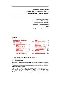
File fragmentation is said to occur when a file is not stored in the correct sequence on consecutive blocks on disk. In other words if a file is fragmented, the sequence of blocks from the start of a file to the end of the file will result in an incorrect reconstruction of the file. Fig. 1 provides a simplified example of a fragmented file. In the figure, the file J1 has been broken into two fragments. The first fragment starts at block 1 and ends at block 4. The second fragment starts at block 8 and ends at block 9. This file is considered to be bi-fragmented as it has only two fragments. Garfinkel (2007) showed that bi-fragmented fragmentation is the most common type of fragmentation, however, files fragmented into three or more pieces are not uncommon. Garfinkel’s fragmentation statistics come from identifying over 350 disks containing FAT, NTFS and UFS file systems.
Fragmentation Point
Header
Footer
1
2
3
4
5
6
7
8
9
J1
J1
J1
J1
?
?
?
J1
J1
Base-fragment
Blocks
Fragment
Fig. 1 – File J1 has been broken into two fragments spanning six blocks, with three blocks in between not belonging to J1.
Fragmentation typically occurs under one of the following scenarios: (1) Low disk space: If the disk space is low and the disk is not defragmented, there may be many small groups of blocks/clusters that are available for storing information. However, future files to be stored may be larger than the largest of these free groups of blocks, and as a result a file may need to be fragmented across multiple of these blocks. (2) Appending/editing files: If a file is saved on disk and then additional files are also saved starting at the cluster that the original file ended at, then fragmentation may occur if the original file is then appended to (and increases in size larger than the cluster size). Some file systems like the Amiga Smart Filesystem may attempt to move the whole file in such scenarios. Some other file systems like UFS attempt to provide ‘‘extents’’ which are attempts to pre-allocate longer chunks in anticipation of appending (McVoy and Kleiman, 1991). Another technique called delayed allocation used in file systems like XFS (Sweeney et al., 1996) and ZFS reserve file system blocks but attempt to delay the physical allocation of the blocks until the operating system forces a flushing of the contents. However, while some of these techniques are able to reduce fragmentation they are unable to eliminate fragmentation completely. (3) Wear-leveling algorithms in next generation devices: Solid State Devices are currently utilizing proprietary wear-leveling algorithms to store data on the disk (STORAGEsearch. com). If the information mapping the logical geometry of the disk to the physical geometry is destroyed or gets corrupted, then any data extracted will be fragmented, with no easy way of determining the correct sequence of blocks to recover files. (4) File system: In rare cases the file system itself will force fragmentation. The Unix File System will fragment files that are long or have bytes at the end of the file that will not fit into an even number of sectors (Carrier, 2005). In Table 1, we give basic definitions concerning fragmentation that will be used throughout the paper and Fig. 1 provides a simple visualization of these definitions. As mentioned earlier, once a file has been fragmented, traditional file carving techniques will fail to recover the file. In the next section, we detail the process required to recover fragmented files and provide a description of existing techniques to achieve this.
S4
digital investigation 5 (2008) S2–S13
Table 1 – Definitions for terms used in paper Term
Definition
Block
This is the size of the smallest data unit that can be written to disk which can be either a disk sector or cluster. To avoid confusion we will use the term block and by will denote the block numbered y in the access order.
Header
This is a block that contains the starting point of a file.
Footer
This is a block that contains the ending data of a file.
Fragment
A fragment is considered to be one or more blocks of a file that are not sequentially connected to other blocks of the same file. Fragmented files are considered to have two or more fragments (though one or more of these may not be present on the disk anymore). Each fragment of a file is assumed to be separated from each other by an unknown number of blocks.
Base-fragment
The starting fragment of a file that contains the header as its first block.
Fragmentation point
This is the last block belonging to a file before fragmentation occurs. A file may have multiple fragmentation points if it has multiple fragments.
Fragmentation area
A set of consecutive blocks by, byþ1, byþ2, byþ3. containing the fragmentation point.
3.
Fragmented file carving
To recover fragmented files correctly a file carver must be able to determine the starting point of a file and the correct blocks that are required to reconstruct the file. In essence it is a three step process: (1) Identify starting point of a file. (2) Identify blocks belonging to file. (3) Order the blocks correctly to reconstruct the file. There are two published techniques that attempt to follow this three step process in differing ways. We now describe these two techniques.
3.1.
Bifragment gap carving
Garfinkel (2007) introduced the fast object validation technique for recovery of fragmented files. This technique recovers files that have headers and footers and are fragmented into two fragments (bi-fragmented). This technique works only for files that can be validated/decoded. Decoding is the process of transforming information in the data blocks associated with a file into its original format that describes the actual content. Many file types, like JPEG, MPEG, ZIP, etc., have to be decoded before their content can be understood. Object validation is the process of verifying if a file obeys the structured rules of its file type. Therefore, an object validator will indicate whether a block violates the structure or rules required of the specific file or file type. For example in the PNG file format,
the data can be validated through cyclic redundancy checking, and a mismatch will indicate either data corruption or fragmentation. A decoder can be trivially used as an object validator by observing whether or not it can correctly decode each block in the sequence. Bifragment Gap Carving (BGC) recovery occurs by exhaustively searching all combinations of blocks between an identified header and footer while excluding different number of blocks until a successful decoding/validation is possible. We now describe bifragment gap carving in greater detail. Let bh be the header block, bf be the last block of the first fragment of a file, bs be the starting block of the second fragment, and bz be the footer block. Blocks bh and bz are known and bf and bs have to be determined. For each gap size g, starting with size one, all combinations of bf and bs are designated so that they are exactly g blocks apart, i.e., s " f ¼ g. A validator/ decoder is then run on the byte stream representing blocks bh to bf and bs to bz. If the validation fails bf and bs are readjusted and the process continued until all choices of bf and bs are tried for that gap size, after which the gap size is incremented. This continues until a validation returns true or the gap size can’t be increased any further. This technique performs satisfactorily when the two fragments are close to each other; however, it has the following limitations for the more general case. (1) The technique does not scale for files fragmented with large gaps. If n is the number of blocks between bh and bz then in the worst case n2 object validations may be required before a successful recovery. (2) For files with more than two fragments, the number of object validations that need to be performed can be impractically high. This is because n " 1 gap sizes have to be used in parallel where n is the number of fragments in the file. It is also very highly unlikely that n can be determined before hand. (3) Successful decoding/validation does not always imply that a file was reconstructed correctly. Decoders will give an error when the data in the blocks do not conform to inherent decoding rules or structure. For example, standard JPEG decoder will stop with an error when a retrieved bit pattern has no corresponding entry in the Huffman code table. Fig. 2 from DFRWS 2007 is an example of a successfully decoded but incorrect JPEG file. (4) Many file types cannot be validated by their structure or do not require decoding. For example, 24-bit BMPs have a header, followed by pixel values where each pixel is represented with three bytes, and has no footer. If a bitmap image is fragmented, any block can be considered to be a candidate for the fragmentation point and the starting point of another fragment. Object validation will fail in such a case. (5) Missing or corrupted blocks for a file will result in the worst case often.
3.2.
Graph theoretic carving
Pal and Memon (2006) formulate the image reassembly problem as a k-vertex disjoint graph problem and reassembly is then done by finding an optimal ordering of blocks. Their
digital investigation 5 (2008) S2–S13
Fig. 2 – Fully validated but incorrect JPEG image from the DFRWS 2007 test set.
technique does not require object validations or decoding, but utilizes a matching metric to indicate the likelihood that a block follows another. For file types that can’t be validated based on their structure (24-bit BMPs), analysis of the actual contents of each file is required to determine if a block should be paired with another block. However, even if a block can be validated the contents of each block are still analyzed and matching metrics created. Matching metrics differ according to the file type. For example in images, the matching metric is generated by analyzing the pixel boundary created by the merging of two blocks. Utilizing the matching metric, they present three algorithms using two heuristics. For the purpose of this paper we describe the Parallel Unique Path (PUP) algorithm using the greedy heuristic as this has the best combination of performance and results. PUP is a modified Dijkstra’s (1959) single source shortest path algorithm, used to reassemble multiple files simultaneously. Starting with the file headers of each file, the best match for each header is chosen and then the header–block pair with the best of all the best matches is merged to the header. The process is repeated until all files are reconstructed. More formally, the k file headers (bh1, bh2, . bhk) are stored as the starting blocks in the reconstruction paths Pi for each of the k files. A set S ¼ (bs1, bs2, . , bsk) of current blocks is maintained for processing, where bsi is the current block for the ith file. Initially, all the k starting header blocks are stored as the current blocks for each file (i.e., bsi ¼ bhi). The best greedy match for each of the k starting blocks is then found and stored in the set T ¼ (bt1, bt2, ., btk) where bti represents the best match for bsi. From the set T of best matches the block with the overall best matching metric is chosen. Assuming that this best block is bti, the following steps are undertaken: (1) (2) (3) (4) (5)
Add bti to reconstruction path of ith file, (i.e., Pi ¼ Pikbti). Replace current block in set S for ith file (i.e., bsi ¼ bhi). Evaluate new set T of best matches for S. Again find best block bti in T. Repeat 1 until all files are built.
S5
Fig. 3 shows an example of the algorithm where there are three files being reconstructed. Fig. 3(a) shows the header blocks H1, H2 and H3 of the three files and their best matches. The best of all the matches is presented with a dotted line and is the H2–6 pair of blocks. Fig. 3(b) now shows the new set of best matches after block 6 has been added to the reconstruction path of H2. Now block 4 is chosen once each for blocks H1 and 6. However, the pair H1–4 is the best and therefore 4 is added to the reconstruction path of H1 and the next best match for block 6 is determined Fig. 3(c). This process continues until all files are reconstructed. While the reported results are very promising, the reassembly requires O(n2) computations, where n is the total number of blocks. Clearly, this system fails to scale when dealing with tens of thousands and even millions of blocks. The reason O(n2) computations are necessary is due to the assumption that fragmentation occurs completely randomly and fragment sizes can be as small as a single block. However, since it assumes random fragmentation, it is able to handle files fragmented into greater than two fragments. Another problem with this technique is that it assumes all blocks are present and that there are no holes.
3.3.
The need for fragmentation point detection
As mentioned both BGC and PUP have problems when dealing with fragmented files. Both require O(n2) computations in the worst case and fail to scale for very large gaps or a file fragmented into many pieces. PUP assumes that fragmentation is completely random, however, as shown in Garfinkel (2007), files with greater than three fragments are very rare, and file systems will almost never fragment a file on a block by block basis. BGC assumes if a file validates it is correct, and does not attempt to validate or score individual pairs of blocks.
Fig. 3 – Simplified example of PUP algorithm.
S6
digital investigation 5 (2008) S2–S13
Both techniques would benefit from being able to identify the base-fragment, which as defined earlier, is the first fragment of a file. More specifically, the last block of the basefragment (i.e., fragmentation point) needs to be detected. In the case of BGC, correct fragmentation point identification allows the assumed fragmentation ending point bf (as defined earlier) to be fixed, and only bs (next fragment starting point) adjusted, thus greatly reducing the number of computations required to validate a file. Even if the fragmentation point was not found, but the fragmentation area was found (a small set of blocks, one of which contains the fragmentation point), bf would only need to be adjusted within the fragmentation area and not from the header. In the case of PUP rather than assuming each block is randomly fragmented, a modification can be made so that if a block is chosen to belong to a file, then the blocks following the chosen one are sequentially compared to the previous block, until a fragmentation point is reached, at which point the algorithm will resume as normal. In the next section we present some simple techniques that can be used for fragmentation point detection.
4.1.
4.
With this type of approach while we may say with certainty that a block does not belong to a particular file, these methods on their own have no way of determining whether or not the previous blocks belong to the file. In the simple example shown in Fig. 4, a JPEG file has been fragmented into two pieces, the first piece, numbering four blocks, and the last piece, numbering three blocks, with three unknown blocks in between. If the first block has the starting (header) signature of another JPEG as shown in Fig. 4b, then this may yield to the decision that fragmentation happened at the fifth block and the last correct block was the fourth block. Moreover, when multiple files of the same type are fragmented together with this approach it will be much harder to detect the presence of fragmentation.
Fragmentation point detection
In Fig. 4, a JPEG image J1 has one file fragmentation point at the fourth block, b4. This implies that blocks 1–4 all belong together in order. If a file is fragmented into more than two pieces, then multiple file fragmentation points will exist, and if the file has no fragmentation then there will be no file fragmentation points. For a file fragmented into more than two pieces, the techniques for identifying the starting file fragmentation point are no different than the techniques for identifying subsequent file fragmentation points. Other than the rare scenario where a file is fragmented because two or more of its fragments are swapped with each other, the gap between each of a file’s fragment ending points and the next correct fragment’s starting point contains data that does not belong to the file. The following tests utilize this information to identify the fragmentation point.
a
1
2
3
4
5
6
7
8
9
J1
J1
J1
J1
?
?
?
J1
J1
Jpeg 1 (J1) contains two fragments (blocks 1-4 and 8-9).
b J1
J1
J1
J1
J2
J2
J2
J1
J1
J2
J2
J1
J1
Blocks 5-7 contain a second Jpeg (J2).
Syntactical tests
With this approach the fragmentation point is detected by identifying whether or not a block belongs to a file in question through one of the following methods: $ Using keywords and signatures indicating different file types. During recovery of a fragmented file, if a block is found to belong to some other file or file type, then it is assumed that a fragmentation point is reached. For example, while recovering a JPEG file if a block is identified to be starting with an HTML file header and has a few other HTML tags, then the fragmentation point is deemed to be detected. Similarly, certain keywords are not expected to be seen during the process of recovery (like invalid JPEG markers), and they can be used for detecting fragmentation points. $ Content analysis indicating incorrect block. An abrupt change in characteristics of the data might potentially indicate a fragmentation point. For example during the recovery of a JPEG file if one were to encounter blocks containing English words, this would indicate that the fragmentation has occurred.
4.2.
Statistical tests
Statistical tests attempt to compare the statistics of each block to a model for each file type and then classify the block. Some examples of statistical tests involve entropy of each block and the OSCAR method (Karresand and Shahmehri, 2006a,b). The Oscar method is based on building models, called centroids, of the mean and standard deviation of the byte frequency distribution of different file types. A block is compared to all models and a determination made as to which file type it seems to conform to. Again these tests suffer from the same problems of being unable to detect the actual fragmentation point that the syntatical tests suffer from, but in addition, blocks can be falsely identified as belonging to another file type.
c J1
J1
J1
J1
?
Blocks 6-7 contain a second Jpeg, but block 5 is unknown.
Fig. 4 – Three examples of different types of blocks in between the two fragments of a JPEG J1.
4.3.
Basic sequential validation
Another simple technique to identify the fragmentation point is to start validating blocks sequentially from the header and continuing on until the validator (decoder) stops with an error. With this technique the last correctly validated block is
digital investigation 5 (2008) S2–S13
deemed to be the fragmentation point. In Fig. 4c validation starts at the first block and continues until it fails at block five, leading to the conclusion that fragmentation point is at block 4. However, it is possible for a validator to successfully validate random blocks of data, which will result in an inaccurate recovery of a file. In fact, this is quite common and is not at all unusual. Take a look at Fig. 5, this shows four images from DFRWS 2007 that were decoded and recovered incorrectly. In DFRWS 2007 sequential decoding alone will result in 8 of 18 JPEGs having the fragmentation point identified incorrectly because multiple blocks beyond the correct fragmentation point will be validated via decoding.
5. Fragmentation point detection using sequential hypothesis testing The main focus of this paper is to improve on PUP and BGC recovery techniques by assuming a more realistic fragmentation scenario where fragments are not randomly scattered but have multiple blocks sequentially stored. However, at the same time we do not want to rely on basic decoding/validation techniques alone to determine where a fragmentation point may occur. We begin by reliably and efficiently detecting the fragmentation point bf and then attempt to find bs, the starting
S7
block of the next fragment. For this purpose, we propose a general fragmentation point detection method which is then utilized as a part of a JPEG image file recovery method.
5.1.
Problem formulation
Recall that we define a base-fragment to be the first fragment of a file. It is composed of k physical data blocks that start with an identifiable bit pattern or a header. Our objective is to determine the total number of blocks k within a base-fragment while minimizing decision errors in falsely identifying the fragmentation point. A decision error can be in two forms: $ a random block that does not belong to the actual fragment is joined, i.e., false addition; or $ a block is separated from the fragment that it belongs to, i.e., false elimination. Hence, given the beginning of a base-fragment, a binary decision is made for each subsequent data block to determine as to whether or not a given data block belongs to the basefragment. This problem can be formulated as a hypothesis test and the corresponding analysis’ framework, based on false-positive and false-detection probabilities, can be extended to false-addition and false elimination probabilities.
Fig. 5 – Four images from the DFRWS 2007 test-set that are decoded incorrectly when doing sequential decoding.
S8
digital investigation 5 (2008) S2–S13
For this purpose, we define a matching metric Yi that may be computed between the data block bi in question and already identified parts of the base-fragment, i.e., b0 ; b1 ; .; bi"1 . In a conventional hypothesis test, for each data block a matching metric is computed and an individual hard decision is made for each block in the order they appear on the storage medium until a fragmentation point is detected. However, since data blocks before the fragmentation point are more likely to be appended to the base-fragment than blocks beyond the fragmentation point, decisions made based on a sequence of blocks, as opposed to a single block, will be more reliable. It should also be noted that in fragmentation point detection, false addition of a random block is typically much more costly than a false elimination of a correct block as those data blocks can be later correctly merged in the next rounds where all the un-attributed data blocks will be matched against successfully reconstructed base-fragments. On the other hand, falsely merged data blocks will not only cause an error in reconstruction of a base-fragment but they may also curtail the correct reconstruction of other fragments (and files) due to loss of continuity.
5.2.
Forward fragment point detection test
In our sequential fragment detection method, the number of observations Y1, Y2, Y3, ., associated with a set of blocks, is not fixed in advance. Instead, they are evaluated collectively as they become available and the test is ended in favor of a decision only when the resulting decision statistic is significantly low or high. Otherwise, if the statistic is in between these two bounds, the test is continued. Starting with the first data block of the base-fragment b0, identified by a fixed pattern or header, subsequent data blocks b1, b2, .bn are appended to b0 and a matching metric, Y1, Y2, ., Yn is obtained in sequence with each addition. Accordingly, we define the hypotheses H0 and H1 as following. H0: blocks b1, b2, ., bn belong in sequence to fragment; H1: blocks b1, b2, ., bn do not belong in sequence to fragment. If the evaluated data blocks b1, b2, ., bn do not yield to a conclusive decision, the test continues with the inclusion of block bnþ1 until one of the hypotheses is confirmed. When hypothesis H0 is true, the evaluated blocks are merged to the base-fragment and a new test is started. Each time the test starts with a new data block in sequence, the matching statistic is computed with respect to the recovered part of the basefragment. The test procedure finalizes after one of the following conditions occur: (1) H1 is achieved. (2) File is completely recovered. (3) An error occurs because no data-block remains or remaining blocks are of a different file type. Let Y represent the sequence Y1, Y2, ., Yn, then in a sequential hypothesis test, a test statistic L is computed as the likelihood ratio of observing sequence Y under the two hypotheses,
which is expressed as the ratio of the conditional distributions of observed matching metrics under H0 and H1 as LðYÞ ¼
PrðYjH1 Þ : PrðYjH0 Þ
(1)
Finally, a decision is made by comparing L to appropriately selected thresholds as 8 < H1 ; LðYÞ > sþ (2) outcome of test ¼ H0 ; LðYÞ < s" : inconclusive; s" < LðYÞ < sþ
That is, if the test statistic (likelihood ratio) is larger than sþ, we assume that hypothesis H1 is true and we have found the fragmentation region. If, on the other hand, test statistic is smaller than s", hypothesis H0 is true and all the fragments are merged and the test continues from the next sequential block. Finally, if neither cases are true testing continues until one of the thresholds is exceeded or end-of-file indicator is reached. The thresholds s" and sþ can be chosen so as to upper bound the probability of errors due to false-eliminations, Pfr, and false additions, Pfe as (Wald, 1947) sþ ¼
1 " Pfe Pfe and s" ¼ : Pfa 1 " Pfa
(3)
Ultimately, the success of the sequential fragment point detection method depends on two factors. The first factor is the choice of the matching-metric whose design has to take into consideration different file types and to capture semantic or syntactic characteristics of the file. The second factor is the accurate determination of the conditional probability mass functions under the two hypotheses. This essentially boils down to obtaining multi-dimensional probability distribution functions under two hypotheses. This requires access to statistics revealing typical number of data blocks in a file fragment which might depend on various parameters like disk size, operating system, disk usage activity, etc. Lacking this information, we assume that the matching-metrics computed from each sequentially stored block are independent and identically distributed (iid). It should be noted that when the data-block locations are not necessarily sequential, iid assumption holds. For example, when all the base-fragments are recovered and subsequent fragment for each file have to be identified, from among all the remaining un-associated data blocks, such a model fits very well. Under iid assumption, the test statistic can be rewritten as n PrðYjH1 Þ Y PrðYi jH1 Þ ¼ : LðYÞh PrðYjH0 Þ i¼1 PrðYi jH0 Þ
(4)
In this case, the test statistic can be incrementally updated with each observation through multiplication by probability ratio associated with the most recently considered data-block. The test statistic is later compared to two thresholds to confirm a hypothesis or to continue the test.
5.3.
Reverse fragmentation point detection
As noted earlier, falsely merging a data-block with or eliminating it from a base-fragment will cause an error in the recovery process. Therefore, our main goal is to determine the fragment boundary by identifying the last data block in sequence that belongs to the base-fragment. Although the
digital investigation 5 (2008) S2–S13
above sequential fragment detection procedure provides an advantage in avoiding false additions and false-eliminations by not making a decision when the information is inconclusive, it also makes accurate fragmentation point detection difficult. This is because each decision is made only after a window of observations is made, and a fragmentation point can be anywhere in this sequence and the test cannot accurately determine it. To cope with this problem we propose to conduct a reverse sequential test every time the (forward) test is inconclusive and the test statistic has to be updated by considering a new data-block. Since for a given window of observations (in a forward test) Y1, Y2, ., Yn the observations towards the end of the block are more likely to be due to random data blocks, by visiting them first reverse test enables more accurate detection of the fragmentation point. In a reverse hypothesis test, the test statistic is computed by traversing the measured matching-metrics in reverse order, i.e., sequence Yn, Yn"1, ., Y2. The test starts by considering Yn only. If the test evaluates H1 as true (bn does not belong to base-fragment), the test is started with Yn"1, and if H1 is evaluated true the reverse test is terminated and the forward testing continues. On the other hand, if the reverse test is inconclusive, the test continues by considering the next to last data blocks, i.e., Yn, Yn"1, until a decision is reached. The fragmentation point is deemed to be the most recently eliminated data-block before the test finally confirms the H1 hypothesis. Fig. 6 shows the flow diagram of the fragment point detection algorithm. Another issue is that the recovery of the base-fragment will be continued via merging new blocks to it every time the test terminates in favor of H0. However, it must be noted that the designated test statistics Y, by its definition, is computed between the known parts of the base-fragment and the blocks in question. Therefore, when both the forward and backward tests are inconclusive and further blocks considered do not form a boundary with the recovered part of the image, the test has to be forcefully terminated. In this case the fragmentation point is assigned to the last block that ended the test in favor of the H0 hypothesis and the blocks that cannot be decided are not added to the base-fragment. Having identified the fragmentation point by itself is not enough (unless the fragmentation point is the end of file) for recovery. Once the base-fragment has been identified, the starting block of the next fragment belonging to the file being reconstructed needs to be determined. In the next section we present a new model for a file carver and then present a modified version of the PUP algorithm that utilizes SHT for a complete recovery solution. It should be remembered that false eliminations (fragmentation point is identified before actual identification point) are preferable over false additions (late detection of fragmentation point), since the second step of the carving (close region sweep, described in the next section) will look at a large number of potential fragments to determine the next block to build the file and the falsely eliminated block will be reconsidered.
6.
Refined file carving
As mentioned earlier, Garfinkel shows that files with greater than four fragments are rare, and file systems will almost
S9
never fragment a file on a block by block basis. What this means is that fragments typically consist of tens if not hundreds or thousands of blocks. We, therefore, propose a carving system that takes into account the fact that fragments typically consist of multiple blocks. In essence we believe that a file carver needs to find the fragmentation points of each file by sequentially testing each block after the header block. So our refined file carver will then contain the following steps: (1) Identify starting block of file. (2) Sequentially check each block after first and determine fragmentation point/file end. (3) If fragmentation point is detected, find starting point of next fragment. (4) Continute with step 2 from starting point of next fragment. The first step in the new file carving system is the same as the traditional step for file carving – identify the data blocks that include the file header. The information from this initial data block is then utilized to recover the base-fragment through analysis of the neighboring blocks until a fragmentation point is detected. Once the fragmentation point is determined the starting block of the subsequent fragment must be determined. Using information from the file recovered so far the next fragmentation point (if the file has more than two fragments) has to be identified. This process is repeated until the file is completely or partially recovered from all the available fragments. Based on this we have modified the PUP algorithm as described earlier with SHT.
6.1.
SHT–PUP
Recall that PUP was an algorithm developed to build multiple files in parallel. Its major drawback was that it did not take into account the fact, that fragments typically consist of many blocks. We have developed a solution for file carving fragmented files using SHT and PUP, called SHT–PUP. SHT– PUP begins by choosing all available headers of a file-type and attempting to use sequential hypothesis testing as described above to determine the base-fragment and fragmentation point. Once the fragmentation point of each basefragment is identified, the remaining available blocks are classified into bins on the basis of file type. This is realized by the use of keyword and statistical tests. Keyword tests utilize the Aho–Corasick algorithm (Aho and Corasick, 1975), which is a string searching algorithm that locates elements of a finite set of strings within an input text. It matches all patterns ‘‘at once’’, so the complexity of the algorithm is linear in the length of the patterns plus the length of the searched text plus the number of output matches. The statistical tests are exactly the same described in Section 4 and involve entropy of the data and the OSCAR method (Karresand and Shahmehri, 2006a,b). It is shown in Garfinkel (2007) that the gap between fragments is rarely more than 80 blocks and that the majority of the time the gap is much smaller. In fact a gap size of 8 blocks occurs in 4327 files and the next closest was a gap size of 32 blocks that occurs in 1519 blocks. As a result, we developed a process called the close region sweep to determine the starting point of the next fragment. For each base-fragment and
S10
digital investigation 5 (2008) S2–S13
Block n Event Yn
Make Decision Y = {Y1, Y2...Yn} (Y)
Fragmentation Point Detected
Yes
Terminal
No
File Recovered No Further Fragmentation Found
Yes
EOF
No No
Fragmentation Point Detected
Yes
(Y) >= µ1
No
(Y)