Current Status of the Hobby-Eberly Telescope∗ wide field upgrade Gary J. Hill, aγ John A. Bootha, Mark E. Cornella, John M. Gooda, Karl Gebhardtb, Herman J. Kriela, Hanshin Leea, Ron Lecka, Walter Moreiraa, Phillip J. MacQueena, Dave M. Perrya, Marc D. Rafala, Tom H. Raffertya, Chuck Ramillera, Richard D. Savagea, Charles A. Taylor IIIa, Brian L. Vattiata, Lawrence W. Ramseyd, Joseph H. Benoc, Timothy A. Beetsc, Jorge D. Esguerrac, Marco Hausere, Richard J. Hayesc, James T. Heislerc, Ian M. Soukupc, Joseph J. Ziererc, Michael S. Worthingtonc, Nicholas T. Mollisonc, Douglas R. Wardellc, Gregory A. Wedekingc, a
McDonald Observatory, University of Texas at Austin, 1 University Station C1402, Austin, TX 78712-0259, USA; b Department of Astronomy, University of Texas at Austin, 1 University Station C1400, Austin, TX 78712-0259, USA; c Center for Electromechanics, University of Texas at Austin, Austin, TX 78758, USA; d Department of Astronomy, Pennsylvania State University, College Park, PA 16802, USA; e Universitäts-Sternwarte München, Scheinerstr. 1 , 81679 München, Germany ABSTRACT The Hobby-Eberly Telescope (HET) is an innovative large telescope of 9.2 meter aperture, located in West Texas at the McDonald Observatory (MDO). The HET operates with a fixed segmented primary and has a tracker which moves the four-mirror corrector and prime focus instrument package to track the sidereal and non-sidereal motions of objects. A major upgrade of the HET is in progress that will increase the pupil size to 10 meters and the field of view to 22′ by replacing the corrector, tracker and prime focus instrument package. In addition to supporting the existing suite of instruments, this wide field upgrade will feed a revolutionary new integral field spectrograph called VIRUS, in support of the Hobby-Eberly Telescope Dark Energy Experiment (HETDEXχ). This paper discusses the current status of this upgrade. Keywords: Telescopes: Hobby-Eberly, HET, HETDEX, wide field corrector, tracker, spectrographs: VIRUS
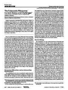
1. INTRODUCTION The HET1-6 (Fig. 1) is the prototype of a new breed of cost-effective large telescopes, and is the basis for the Southern African Large Telescope (SALT)7. HET is an innovative telescope with an 11 m hexagonal-shaped spherical mirror made of 91 1-m hexagonal segments that sits at a fixed zenith angle of 35ο. It can be moved in azimuth to access about 70% of the sky visible at McDonald Observatory (δ = -10.3o to +71.6o). The pupil is 9.2 m in diameter, and sweeps over the primary mirror as the x-y tracker follows objects for between 50 minutes (in the south at δ = -10.0o) and 2.8 hours (in the north at δ = +67.2o). The maximum time on target per night is 5 hours and occurs at +63o. The HET primary mirror has a radius of curvature of 26164 mm, and the current 4-mirror double-Gregorian type corrector is designed to produce images with FWHM < 0.6 arcsec in the absence of seeing, over a 4 arcmin (50 mm) diameter science field of view. Detailed descriptions of the HET and its commissioning can be found in refs 1-6. The HET was originally envisioned as a spectroscopic survey telescope, able to efficiently survey objects over wide areas of sky. While the telescope has been very successful at observing large samples of objects such as QSOs and extrasolar planets spread over the sky with surface densities of around one per 10 sq. degrees, the HET design coupled ∗
The Hobby-Eberly Telescope is operated by McDonald Observatory on behalf of the University of Texas at Austin, the Pennsylvania State University, Ludwig-Maximillians-Universität München, and Georg-August-Universität, Göttingen γ G.J.H.: E-mail:
[email protected] χ
http://hetdex.org/
Ground-based and Airborne Telescopes IV, edited by Larry M. Stepp, Roberto Gilmozzi, Helen J. Hall, Proc. of SPIE Vol. 8444, 84440K · © 2012 SPIE · CCC code: 0277-786/12/$18 · doi: 10.1117/12.925435
Proc. of SPIE Vol. 8444 84440K-1 Downloaded From: http://spiedigitallibrary.org/ on 07/01/2013 Terms of Use: http://spiedl.org/terms
with the limited field of view of the corrector hampers programs where objects have higher sky densities. In seeking a strong niche for the HET going forward, the HET field of view will be increased from 4′ to 22′ so that it can accommodate the Visible Integral-field Replicable Unit Spectrograph (VIRUS)8-11, an innovative, highly multiplexed spectrograph that will place at least 33,600 fibers on sky simultaneously and open up the emission-line universe to systematic surveys for the first time, uncovering populations of objects selected by their line emission rather than by their continuum emission properties. The primary motivation for the HET wide field upgrade (WFU) and VIRUS is to execute the Hobby-Eberly Telescope Dark Energy Experiment (HETDEX12), which will map the spatial distribution of about 0.8 million Lyα emitting galaxies (LAEs) with redshifts 1.9 < z < 3.5 over a 420 sq. deg. area (9 Gpc3) in the north Galactic cap. This dataset will constrain the expansion history of the Universe to 1% and provide significant constraints on the evolution of dark energy. The requirement to survey large areas of sky with VIRUS plus the need to acquire wavefront sensing stars to provide full feedback on the tracker position led us to design an ambitious new corrector employing meter-scale aspheric mirrors and covering a 22-arcmin diameter field of view. The WFU deploys the wide field corrector (WFC13), a new tracker14, a new prime focus instrument package (PFIP15), and new metrology systems16-20.
Figure 1. The figure on the left shows the HET pre WFU with the dome shutter open. The figure on the right is a close up view of the top of the HET revealing the primary mirror, and telescope structure which supports the tracker and PFIP.
2. TELESCOPE CONFIGURATION The basic configuration of the HET will remain unchanged in the upgrade, but the new tracker has a much higher payload of 3 tonnes due to the new WFC and PFIP. VIRUS is fiber-fed which allows the mass of the spectrographs to be carried in four enclosures (two on each side of the telescope). Since each enclosure contains 24 pairs of spectrographs (VIRUS units have two spectrograph channels, and disperse the light from an IFU with 448 fibers), there is capacity for a total of 192 spectrographs. The likely deployed size of VIRUS will be between 75 and 82 units (up to 164 spectrographs with coverage per observation of over 60 sq. arcminutes. Figures 2 and 3 show CAD renderings of the telescope post upgrade. The location of the spectrograph enclosures was constrained by many factors, including: ●
Desire to maximize throughput (especially in the UV) by minimizing the length of the fiber feeds
●
Minimize the mechanical stress on the fiber feeds
Proc. of SPIE Vol. 8444 84440K-2 Downloaded From: http://spiedigitallibrary.org/ on 07/01/2013 Terms of Use: http://spiedl.org/terms
●
Maintain ample man lift access to the telescope’s interior structure. This is particularly important because the mirror segments are cleaned with CO2 several times a week, and the individual mirror segments are recoated on a regular basis.
●
Prevent wind-induced motion of the spectrograph enclosures (which have an effective wind sail area on the order of 50 m2) from shaking the telescope structure and causing image degradation
●
Minimize complexity, weight, and cost of the structure which supports the spectrograph enclosures
The final enclosure locations were a compromise that was strongly influenced by the need to maintain man lift access to the primary mirror.
Figure 2. HET post WFU with VIRUS spectrograph enclosures installed. The spectrograph enclosures are shown without their skins and covers to reveal the VIRUS spectrographs.
Proc. of SPIE Vol. 8444 84440K-3 Downloaded From: http://spiedigitallibrary.org/ on 07/01/2013 Terms of Use: http://spiedl.org/terms
Figure 3. Close up view of the top of the telescope post WFU with key components indicated. New features compared to the current HET tracker are the center drive on the y-axis and the addition of the y-axis constant force drive (CFD).
3. TRACKER A new tracker is needed to accommodate the size and five-fold weight increase of the new WFC and PFIP. It will be a third generation evolution of the trackers for HET and SALT, and is in essence a precision six-axis stage (Figs. 3, 4). The tracker bridge spans the upper hexagon of the telescope structure, moving on two x-axis stages. A carriage moves up and down in the y-axis, and supports the hexapod which provides the fine adjustment in the other degrees of freedom. The total volume of motion is about 7x7x4 m3, and the required accuracy is on the order of 10 μm. The tracker is being developed by the Center for Electro-Mechanics (CEM) at the University of Texas at Austin21-30, with integration complete at the CEM facility, and testing about to begin. The tracker is a highly optimized machine that was subject to numerous challenging design constraints. This includes the following: ●
Accurately positioning the WFC/PFIP during observations to maintain image quality. The design goal is to maintain the position and orientation of the WFC with respect to the primary mirror to within a decenter of 10μm, a defocus of 10 μm, and tip/tilt to within 4″.
●
Minimizing tracker obstruction of the primary mirror with a highly optimized bridge structure.
●
Reducing the overall weight of the tracker to keep it within the load bearing capacity of the existing telescope structure, and to achieve a fundamental mode of the entire telescope above 5 Hz.
Proc. of SPIE Vol. 8444 84440K-4 Downloaded From: http://spiedigitallibrary.org/ on 07/01/2013 Terms of Use: http://spiedl.org/terms
●
Accommodating the limited overhead dome crane lifting capacity and hook height constrained the maximum weight and geometry of the tracker carriage, hexapod, and PFIP components. These constraints precluded the possibility of assembling the entire carriage/hexapod/PFIP assembly on the ground and then lifting it to the top of the telescope as a single assembly. Instead, many smaller assemblies must be lifted to the top of the telescope (one at a time) and then assembled at height over the primary mirror, a precarious process which subjects the primary mirror to increased risk of damage.
●
Preventing the tracker carriage/hexapod/PFIP assembly from ever experiencing a down hill free fall along the tracker Y axis. Such an accidental event could result in catastrophic damage to the telescope. CEM conducted a thorough failure mode and effects analysis (FMEA26) which resulted in a redundant design solution that has multiple layers of failure prevention. This includes the design of constant force actuator safety system27 which is similar to the one used on the Southern African Large Telescope.
●
Preventing a tracker hexapod actuator failure from damaging the PFIP/WFC. This required a thorough understanding of the volume swept out by the PFIP/WFC for all plausible combinations of the hexapod actuator lengths24.
●
Accommodating the limited straightness, flatness, and flexure of the tracker x-axis and y-axis linear bearing rail mounting surfaces, and long linear axis travel ranges (especially with regards to lead screw sag and critical speed).
Differences between the new tracker and the existing HET tracker include the provision of a center drive on the yaxis (rather than a side drive screw) and the addition of a constant-force drive winch system as a safety measure on the y-axis. Both changes were necessitated by the significantly higher moving mass and analysis that showed unacceptable forces generated by impact of the tracker payload should there be a run-away in the y-axis, down-hill. The constant force drive uses an independent drive system with load-cell feedback to un-weight part of the load, but its primary purpose is to sense a runaway condition and apply a brake that is independent of the rest of the control system. This scheme provides safety for both equipment and personnel, and was settled upon following a detailed failure modes and effects analysis. The hexapod actuators were manufactured by ADS International (Valmadrera, Italy) in collaboration with CEM and MDO24. A hydraulic test bed for the struts was built at CEM to test them in compression and tension over their operating range and to map residual errors in position versus encoder values. The actuator shaft rotations are encoded. A laser tracker (LT, model API T3-40 with DMI) was used for this “mount-model” which exhibited only very small deviations from linear. Assembly into the hexapod configuration was first done in a vertical orientation. Following tests and initial characterization the assembled hexapod was mounted at 35 degrees in its test stand to mimic the posture on HET. In this configuration the control system was tested and positions confirmed with the LT to verify algorithms. The hexapod was subsequently mounted on the Y carriage following testing of the x- and y-axes with a dummy test mass on the carriage. The tracker motion control system (TMCS) is based in the Matlab-Simulink environment in a dSPACE controller25,28. The higher-level Telescope Control System (TCS) communicates with the tracker through a well-defined API, and handles all the high-level functions and most of the coordinate transforms and mount models for the tracker. Development of the TMCS at CEM has lagged significantly, demonstration of tracks commanded by TCS are expected in the next month and the tracker is projected to be ready for final testing and mount-model generation in Q3 2012, about a year late. However, preliminary testing and mount-model work indicates that the tracker will meet all its requirements. Testing will continue through March 2013, and the tracker is scheduled for disassembly and transport to HET starting in May 2013.
Proc. of SPIE Vol. 8444 84440K-5 Downloaded From: http://spiedigitallibrary.org/ on 07/01/2013 Terms of Use: http://spiedl.org/terms
Figure 4. Assembled tracker in the CEM high bay. The hexapod struts can be identified by their blue casings.
4. PRIME FOCUS INSTRUMENT PACKAGE The PFIP15 rides on the tracker and consists of several subassemblies. The Wide Field Corrector (WFC) mounts on a strongback on a three ball-in-vee kinematic mount. The structure of PFIP is built up around the corrector. The focal plane assembly (FPA), shown in Fig. 5, contains all the hardware at the focus of the telescope including the acquisition and guiding (AG) assembly, fiber instrument feeds, shutter, and electronics hardware. The Lower Instrument Package (LIP) is mounted to the input end of the wide field corrector and is a platform for the entrance window changer, tip-tilt camera, and facility calibration unit (FCU) output head. A set of temperature controlled, insulated enclosures house electronics hardware and the facility calibration unit input hardware. The pupil plane assembly (PPA) is located in between the wide field corrector and the focal plane assembly. It contains a stationary and moving set of baffles at the exit pupil of the telescope and a platform for exit windows and the atmospheric dispersion compensator for the wide field corrector. The heart of the metrology system for the WFU is AG assembly (Fig 5 & 6), which mounts the guide probe assembly, the acquisition camera, a wavefront sensor and a pupil viewer. The guide probe assembly is used for star guiding of the telescope and wavefront sensing feedback to the telescope focus. There are four probes; two imaging probes and two wave-front sensing probes. Each probe consists of a probe optical head, containing the necessary optics coupled to a coherent fiber bundle purchased from Schott. Images incident to the fiber bundle input are captured by a remote camera system at the bundle output. Each probe optical head is mounted to an arm for moving the probe radially in the field with a range of 8-11 arcminutes from the center of the telescope’s field. The positioning accuracy requirement of the guide probes is 20 microns on the spherical focal surface. To achieve this, both mechanical position actuation and encoding required a high level of precision.
Proc. of SPIE Vol. 8444 84440K-6 Downloaded From: http://spiedigitallibrary.org/ on 07/01/2013 Terms of Use: http://spiedl.org/terms
Figure 5. Renderings of the PFIP. On the right the full assembly is shown with major sub-assemblies indicated. On the left is an exploded view of the FPA showing its major components. The FPA contains most of the complexity of the instrument, including the acquisition and guiding assembly with guide probes and wavefront sensors.
The prime focus shutter which shutters VIRUS and LRS2 is a rotary-type shutter initially inspired by the FORS shutter design. The shutter “blade” is a rotating disc with an aperture cut out of one section. Exposure occurs when the disc rotates so that the aperture aligns with the clear aperture of the focal surface. The shutter blade itself is a custom cut sheet of carbon fiber reinforced plastic (CFRP) purchased from Allred Associates. The shutter blade is fastened to a hardened steel ring. The inner diameter of the ring has a vee profile, which rides on 6 ball-bearing guide wheels mounted to the shutter chassis. The outer diameter of the ring has a toothed profile which meshes with a Kevlar reinforced toothed drive belt. The belt is driven by a toothed pulley driven by a DC servo motor. An absolute rotary encoder is mounted at the center of the shutter blade. A flexural mount on the encoder body ensures concentricity between encoder axis and shutter axis. The timing and position control of the shutter is achieved using position, velocity, and time (PVT) trajectory interpolation. Minimum required exposure is 1 second which is easily achieved by ramping up to a constant velocity. Longer exposures typically have an open command and a close command with a pause between for the exposure time. Tests have verified 5 millisecond accuracy for the timing of the shutter over thousands of actuations. The dithering mechanism (Fig. 7) is a three position actuator that offsets the fiber feeds so that a set of three exposures will fill the interstitial space between fibers in a single VIRUS IFU. The device is actuated by six Festo “fluidic muscle” pneumatic actuators; two are active in each of three positions. These actuators were selected for their high initial force and small diameter. They are particularly well suited for short-throw applications. A special pin flexure of titanium was designed to control the motion of the dithering mechanism. The design required a ~150 micron movement in a plane normal to the optical axis but only allowed for ~5 micron motion parallel to the optical axis despite the varying loads from the fiber feeds. Repeatability of motion has been demonstrated to be 5 microns rms.
Proc. of SPIE Vol. 8444 84440K-7 Downloaded From: http://spiedigitallibrary.org/ on 07/01/2013 Terms of Use: http://spiedl.org/terms
The LIP mounts to the WFC directly, and houses the entrance window selector and the facility calibration unit (FCU) input head. The FCU illuminates the pupil and focal surface of HET with a pattern almost indistinguishable from that obtained on sky31. Figure 6. Guide probe assembly. Left shows the assembly undergoing performance tests with the LT. Peak to peak error is 30 microns, well within specification for focus. The layout and ability for the probes to nest very closely while avoiding any collision is shown on the right.
Figure 7. Dither mechanism that moves the VIRUS IFU heads between three precisely defined and repeatable positions. The exploded view on the left shows the components. The titanium flexures ensure that the assembly will carry the loads it will see during operation and still allow the small motions required. Right shows the assembled mechanism undergoing tests in the lab.
Proc. of SPIE Vol. 8444 84440K-8 Downloaded From: http://spiedigitallibrary.org/ on 07/01/2013 Terms of Use: http://spiedl.org/terms
5. METROLOGY SYSTEMS HET requires constant monitoring and updating of the position of its components in order to deliver good images. The WFC must be positioned to 10 μm precision in focus and X, Y, and 4.0 arcsec in tip/tilt with respect to the optical axis of the primary mirror. This axis changes constantly as the telescope tracks, following the sidereal motions of the stars. Tilts of the WFC cause comatic images. In addition, the global radius of curvature of the primary mirror can change with temperature (as it is essentially a glass veneer on a steel truss), and needs to be monitored. The segment alignment maintenance system (SAMS) maintains the positions of the 91 mirrors with respect to each other, but is less sensitive to the global radius of curvature of the surface. The feedback to maintain these alignments requires excellent metrology, which is provided by the following subsystems: • • • •
Guide probes to monitor the position on the sky, and plate scale of the optical system, and monitor the image quality and atmospheric transparency Wavefront sensors (WFS) to monitor the focus and tilt of the WFC Distance measuring interferometer (DMI) to maintain the physical distance between the WFC and primary mirror Tip-tilt sensor (TTS) to monitor the tip/tilt of the WFC with respect to the optical axis of the primary mirror
The upgrade adds wavefront sensing 16-20 to HET in order to close the control loop on all axes of the system, in conjunction with the DMI adapted from the current tracker metrology system and a new TTS15 (Fig. 8). There is redundancy built into the new metrology system in order to obtain the highest reliability. Two guide probes distributed around the periphery of the field of view provide feedback on position, rotation, and plate scale, as well as providing a record of image quality and transparency. The alignment of the corrector is monitored by the wavefront sensors as well as by the DMI and TTS. The radius of curvature of the primary mirror is monitored by the combination of focus position from the WFS with the physical measurement from the DMI and checked by the plate scale measured from the positions of guide stars on the guide probes. The SAMS edge-sensors provide a less sensitive but redundant feedback on radius of curvature as well.
Figure 8: New Tip-Tilt Sensor (TTS) for the WFU. This metrology instrument monitors the angle between the WFC and the normal to the primary mirror as the HET tracks by projecting a 1.6 micron wavelength beam and measuring the position of the return reflection on a standard CCD camera via an IR to visible light converter reimaging lens system. Two guide probes will use small pick-off mirrors and coherent imaging fiber bundles to select guide stars from the outer annulus of the field of view. They will be located ahead of the focal surface, before the shutter. Each will range around the focal surface on precision encoded stages, accessing a 180 degree sector. They are designed to have a small size to reduce shadowing of the focal surface, and each will have a field of view of 22.6 arcsec on a side. During setup on a new target, they will be driven to pre-defined positions, and the initial pointing will be made by centering the guide stars in the probes. This system is a significant upgrade from the current pellicle-based guiders. Two Shack-Hartmann (S-H) wavefront sensors will also range in the outer field. Their function is to provide feedback on the low-order errors in the wavefront (focus, coma, spherical, and astigmatism)16-19. These errors are caused
Proc. of SPIE Vol. 8444 84440K-9 Downloaded From: http://spiedigitallibrary.org/ on 07/01/2013 Terms of Use: http://spiedl.org/terms
by misalignment of the corrector with the primary mirror focal surface and by global radius of curvature and astigmatism errors in the primary mirror shape. Updates will be generated approximately once per minute. In addition to the WFS probes there will be an analysis wavefront sensor as part of the acquisition camera that will allow more detailed feedback analysis of the image quality, simultaneous with the operation of the WFS probes, independent of seeing. Simulations show that a S-H system with 7x7 sub-apertures across the pupil can meet the requirements using 18th magnitude stars. We have deployed a wavefront sensor for the current HET with 19 sub-apertures across the pupil and the final design is being informed by direct experience with this sensor. The design of the wavefront sensors is straightforward, but their application to the HET, with the varying illumination of the telescope pupil during a track, requires development of a robust software system for analysis of the sensor data to produce reliable wavefront information16.
Figure 9. Layout of WFC mirrors and structure (left), and WFC structure undergoing tests with dummy mirrors to confirm performance and tune flexures for M4 supports (right).
6. WIDE FIELD CORRECTOR The new corrector (Fig. 9) has improved image quality and a 10 m pupil diameter. The periphery of the field will be used for guiding and wavefront sensing to provide the necessary feedback to keep the telescope correctly aligned. The WFC will give 30 times larger observing area than the current HET corrector. It is a four-mirror design with two concave 1 meter diameter mirrors, one concave 0.9 meter diameter mirror, and one convex 0.23 m diameter mirror. The corrector is designed for feeding optical fibers at f/3.65 to minimize focal ratio degradation, and so the chief ray from all field angles is normal to the focal surface. This is achieved with a concave spherical focal surface centered on the exit pupil. The primary mirror spherical aberration and the off-axis aberrations in the wide field are controllable due to the first two mirrors being near pupils, and the second two mirrors being well separated from pupils. The imaging
Proc. of SPIE Vol. 8444 84440K-10 Downloaded From: http://spiedigitallibrary.org/ on 07/01/2013 Terms of Use: http://spiedl.org/terms
performance is 0.6 arcsec or better over the entire field of view, and vignetting is minimal. The WFC is being manufactured by the University of Arizona College of Optical Sciences (OSC)13. Delivery is projected for Q2 2013. Figuring and polishing of the three large mirrors was done at OSC on robotic swing-arm machines and tested with swing-arm profilometry using non-contact sensors (Fig. 10). The degree of aspheric departure and the steepness of the surfaces proved a challenge, but all mirrors are now polished. Interferometric confirmation of figures using phase etched computer generated holograms (CGHs) is proceeding. Mirror M2 is complete and the outer annulus of M3 is tested and confirmed to match the profilometer data. Testing of the inner part of M3 and of M5 is proceeding and all indications are that the figures and polish meet or exceed requirements. As part of the figure test, centering fixtures are being aligned that will be used in the final alignment of the WFC assembly. These center fixtures have CGH targets that when centered will provide a reference that locates the center and normal of each mirror surface. M4 utilized a transmission test with CGH, and is complete and ready for coating (Fig. 10). Reflective coatings for the WFC are required to have high reflectance (95% or better from 350 nm 1800 nm), and are challenging, being based on silver and multiple dielectric layers. Experience with coating degradation on the current HET corrector led us to adopt a sealed design for the WFC with entrance and exit windows and careful sealing of the WFC housing. The WFC will be purged with either instrument air or nitrogen gas. The facility will have a large volume of nitrogen available from the cooling system for VIRUS, and this may be utilized to provide an over-pressurized oxidation-free environment for the mirror coatings to achieve the longest life possible. Coating of M4 is awarded to STF, and the contract for the large mirrors is in the process of being awarded. The smaller M4 sees a very wide range of incident angles, and requires a more complex coating than the others. Mirror coating is expected to be complete towards the end of 2012. The structure of the WFC is a space frame which is mounted kinematically into the PFIP and tracker (Fig. 9). FEA analysis focused on maintaining critical alignments between the mirrors as the corrector moves between the extreme angles of 25 to 45 degrees. In particular the separation of M4 and M5 has to be held to a few microns, and their very different masses make this a challenge. OSC designed tunable flexures for the M4 supports that allow the relative motion of these two mirrors to be tuned. MDO supplied test masses that mimic the mass and center of gravity of the mirrors to allow testing of the structure and tuning of these flexures prior to completion of the mirrors, and tests with a laser tracker indicate all displacements are within specification and have allowed the tuning to the flexures to null out the relative motion of M4 and M5. The WFC structure is now qualified and will shortly be sent for finishing.
Figure 10. Polishing of M3 mirror on robotic machine at OSC (left), and M4 (convex aspheric) metrology setup for bonding and aligning center reference CGH (right). Final integration and alignment of the WFC will be done following coating. Alignment will be made using an interferometer and autocollimator to set centration and tilts and a LT will be used to set separations. Then CGH tests of the M4/M5 pair and of the whole system will be used to evaluate the alignment of the assembly. Independent tests with a
Proc. of SPIE Vol. 8444 84440K-11 Downloaded From: http://spiedigitallibrary.org/ on 07/01/2013 Terms of Use: http://spiedl.org/terms
custom wavefront sensor are also being planned by MDO staff to provide independent confirmation that the system is meeting specification. This wavefront sensor will also be used to check alignment once the corrector is delivered to HET and is intended to be deployed for tests even with the WFC mounted in the tracker.
7. SOFTWARE The software effort is well into the implementation phase. It uses a component architecture (Figure 11) built around object oriented programming techniques, and provides a high degree of configuration, automation, and scalability32. It consists of a network of control systems, each of which models a sub-set of closely coupled hardware. The control systems (CS) communicate with each other using abstract interfaces and a simple but flexible messaging scheme. Each system is responsible for specific functions based on type or proximity to hardware, and is designed to be run autonomously. The primary systems for the WFU and VIRUS are the Telescope CS (TCS), the Prime Focus Instrument Package CS, the Payload Alignment CS (PAS), the VIRUS Data Acquisition CS (VDAS), and the Tracker motion CS (TMCS), along with a centralized logging system. In addition to these control systems, GUI interfaces for the telescope operator and resident astronomer have been developed. Individually, a control system is an autonomous unit, with a state machine driven program engine and a built in Python scripting interpreter. They are configured at run time using a configuration script, allowing easy testing and simulation. The primary operating system is Red Hat Enterprise Linux 6.x, 64-bit. The software was developed with an agile process using the standard GNU toolchain, and widely available libraries. The TCS is ready to test with the tracker TMCS with trajectories and moves as soon as the TMCS is ready. The PAS camera chain works for both of our adopted camera product lines, and all algorithms of the metrology solver have been established. The software for VDAS has read out CCDs and will be developed further as larger subsections of the VIRUS detector system come on line. Overall the software schedule tracks the availability of hardware, and will be ready for installation and commissioning in the second half of 2013.
Figure 11. Software system architecture diagram.
Proc. of SPIE Vol. 8444 84440K-12 Downloaded From: http://spiedigitallibrary.org/ on 07/01/2013 Terms of Use: http://spiedl.org/terms
8. INSTALLATION AND SUMMARY It is crucial that when we take HET off line to install the WFU and VIRUS, we bring it back into operation in as short a time as possible and are able to predict the down-time accurately. Since the HET is a successful working telescope, we must ensure that risks to schedule and performance are retired before the installation starts. We have developed a detailed installation plan that incorporates effort estimates derived from experience assembling the tracker at CEM. The trigger point for starting the take down of the HET will be the retirement of risk on the WFC alignment. This requires the WFC to pass its system alignment test. We will hold a Readiness Review with external experts to establish that all subsystems are ready for installation, and to approve proceeding with the dismantling of the current HET tracker. We expect to hold the review some time in Q2 2013. Installation and commissioning at HET is anticipated to begin mid 2013 with science observations resuming at the end of 2014. The HETDEX survey will run form 2014 through 2016.
ACKNOWLEDGEMENTS HETDEX is run by the University of Texas at Austin McDonald Observatory and Department of Astronomy with participation from the Ludwig-Maximilians-Universität München, Max-Planck-Institut für Extraterrestriche-Physik (MPE), Leibniz-Institut für Astrophysik Potsdam (AIP), Texas A&M University, Pennsylvania State University, Institut für Astrophysik Göttingen, University of Oxford and Max-Planck-Institut für Astrophysik (MPA). In addition to Institutional support, HETDEX is funded by the National Science Foundation (grant AST-0926815), the State of Texas, the US Air Force (AFRL FA9451-04-2-0355), by the Texas Norman Hackerman Advanced Research Program under grants 003658-0005-2006 and 003658-0295-2007, and by generous support from private individuals and foundations. We thank the following reviewers for their valuable input at various stages in the project: Science Requirements Review 6-26-07, Roland Bacon, Gary Bernstein, Gerry Gilmore, Rocky Kolb, Steve Rawlings Preliminary Design Review 4-10-08, Bruce Bigelow, Gary Chanan, Richard Kurz, Adrial Russell, Ray Sharples PFIP Integration and Alignment Review 7-26-11, Larry Ramsey, Bruce Bigelow, Steve Schmee, Mike Smith Tracker Factory Acceptance Test Plan Review 3-8-11, Povilas Palunas, Jeffrey Kingsley, Dave Chaney
REFERENCES [1] J.A. Booth, M.J. Wolf, J.R. Fowler, M.T. Adams, J.M. Good, P.W. Kelton, E.S. Barker, P. Palunas, F.N. Bash, L.W. Ramsey, G.J. Hill, P.J. MacQueen, M.E. Cornell, & E.L. Robinson, “The Hobby-Eberly Telescope Completion Project”, in Large Ground-Based Telescopes, Proc SPIE 4837, 919 (2003) [2] J.A. Booth, P.J. MacQueen, J.G. Good, G.L. Wesley, P.R. Segura, P. Palunas, G.J. Hill, R.E. Calder, "The Wide Field Upgrade for the Hobby-Eberly Telescope", Proc. SPIE, 6267-97 (2006) [3] G.J. Hill, P.J. MacQueen, M.D. Shetrone, & J.A. Booth, “Present and future instrumentation for the Hobby-Eberly Telescope”, Proc. SPIE, 6269-5 (2006) [4] G.J. Hill, P.J. MacQueen, P. Palunas, S.I. Barnes, M.D. Shetrone “Present and future instrumentation for the HobbyEberly Telescope”, Proc. SPIE, 7014-5 (2008) [5] R.D. Savage, J.A. Booth, K. Gebhardt, J.M. Good, G.J. Hill, P.J. MacQueen, M.D. Rafal, M.P. Smith, B.L. Vattiat, “Current Status of the Hobby-Eberly Telescope Wide Field Upgrade and VIRUS”, Proc. SPIE, 7012-10 (2008) [6] R. Savage, et al., “Current Status of the Hobby-Eberly Telescope wide field upgrade,” Proc. SPIE, 7733-149 (2010) [7] D.A.H. Buckley, G.P. Swart, J.G. Meiring, “Completion of the Southern African Large Telescope”, Proc. SPIE, 6267-19 (2006) [8] G.J. Hill, P.J. MacQueen, P. Palunas, A. Kelz, M.M. Roth, K. Gebhardt, & F. Grupp, “VIRUS: a hugely replicated integral field spectrograph for HETDEX”, New Astronomy Reviews, 50, 378 (2006); G.J. Hill, P.J. MacQueen, J.R. Tufts, A. Kelz, M.M. Roth, W. Altmann, P. Segura, M. Smith, K. Gebhardt, & P. Palunas, “VIRUS: a massivelyreplicated IFU spectrograph for HET,” Proc. SPIE, 6269-93 (2006) [9] G.J. Hill, P.J. MacQueen, M.P. Smith, J.R. Tufts, M.M. Roth, A. Kelz, J. J. Adams, N. Drory, S.I. Barnes, G.A. Blanc, J.D. Murphy, K. Gebhardt, W. Altmann, G.L. Wesley, P.R. Segura, J.M. Good, J.A. Booth, S.-M. Bauer, J.A. Goertz, R.D. Edmonston, C.P. Wilkinson, “Design, construction, and performance of VIRUS-P: the prototype of a highly replicated integral-field spectrograph for HET”, Proc. SPIE, 7014-257 (2008) [10] G.J. Hill, et al., “VIRUS: a massively replicated 33k fiber integral field spectrograph for the upgraded HobbyEberly Telescope,” Proc. SPIE, 7735-21 (2010)
Proc. of SPIE Vol. 8444 84440K-13 Downloaded From: http://spiedigitallibrary.org/ on 07/01/2013 Terms of Use: http://spiedl.org/terms
[11] G.J. Hill, et al., “VIRUS: production of a massively replicated 33k fiber integral field spectrograph for the upgraded Hobby-Eberly Telescope,” Proc. SPIE, 8446-21 (2012) [12] Hill, G.J., Gebhardt, K., Komatsu, E., Drory, N., MacQueen, P.J., Adams, J.A., Blanc, G.A., Koehler, R., Rafal, Roth, M.M., Kelz, A., Grupp, F., Murphy, J., Palunas, P., Gronwall, C., Ciardullo, R., Bender, R., Hopp, U., and Schneider, D.P., 2008, “The Hobby-Eberly Telescope Dark Energy Experiment (HETDEX): Description and Early Pilot Survey Results”, in Panoramic Views of the Universe, ASP Conf. Series, vol 399, p 115 (arXiv:0806.0183v1) [13] J. H. Burge, S. D. Benjamin, M. B. Dubin, S. M. Manuel, M. J. Novak, Chang Jin Oh, M. J. Valente, C. Zhao, J. A. Booth, J. M. Good, G. J. Hill, H. Lee, P. J. MacQueen, M. D. Rafal, R. D. Savage, M. P. Smith, B. L. Vattiat, “Development of a wide-field spherical aberration corrector for the Hobby Eberly Telescope”, Proc. SPIE, 7733-51 (2010) [14] J. Good, et al., “Design of performance verification testing for HET wide-field upgrade tracker in the laboratory,” Proc. SPIE, 7739-152 (2010) [15] B.L. Vattiat, et al., “Design, testing, and performance of the Hobby Eberly Telescope prime focus instrument package,” Proc. SPIE, 8446-269 (2012) [16] H. Lee, et al., “Analysis of active alignment control of the Hobby-Eberly Telescope wide field corrector using Shack-Hartmann wavefront sensors,” Proc. SPIE, 7738-18 (2010) [17] H. Lee, et al., “Metrology systems for the active alignment control of the Hobby-Eberly Telescope wide-field upgrade,” Proc. SPIE, 7739-28 (2010) [18] H. Lee, et al., “Orthonormal aberration polynominals over arbitrarily obscured pupil geometries for wavefront sensing in the Hobby-Eberly Telescope,” Proc. SPIE, 7738-59 (2010) [19] H. Lee, et al., “Metrology systems of Hobby-Eberly Telescope wide field upgrade,” Proc. SPIE, 8444-181 (2012) [20] H. Lee, et al., “Surface figure measurement of the Hobby-Eberly Telescope primary mirror segments via phase retrieval and its implications for the wavefront sensing in the new wide-field upgrade,” Proc. SPIE, 7738-58 (2010) [21] M.S. Worthington, et al., “Design and analysis of the Hobby-Eberly Telescope Wide Field Upgrade bridge,” Proc. SPIE, 7733-147 (2010) [22] N.T. Mollison, et al., “Design and development of a long-travel positioning actuator and tandem constant force actuator safety system for the Hobby-Eberly Telescope wide field upgrade,” Proc. SPIE, 7733-150 (2010) [23] G.A. Wedeking, et al., “Kinematic optimization of upgrade to the Hobby-Eberly Telescope through novel use of commercially available three-dimensional CAD package,” Proc. SPIE, 7733-148 (2010) [24] J.J. Zierer, Jr., G.A. Wedeking, J.H. Beno, J.M. Good, “Design, testing, and installation of a high-precision hexapod for the Hobby-Eberly Telescope dark energy experiment (HETDEX),” Proc. SPIE, 8444-176 (2012) [25] J.R. Mock, et al., “Tracker controls development and control architecture for the Hobby-Eberly Telescope Wide Field Upgrade,” Proc. SPIE, 7733-152 (2010) [26] R.J. Hayes, et al., “Use of failure modes and effects analysis in design of the tracker system for the HET wide-field upgrade,” Proc. SPIE, 8449-56 (2012) [27] M.S. Worthington, et al., “Design and development of a high-precision, high-payload telescope dual-drive system,” Proc. SPIE, 7733-201 (2010) [28] J.H. Beno, et al., “HETDEX tracker control system design and implementation,” Proc. SPIE, 8444-211 (2012) [29] I.M. Soukup et al., “Testing, characterization, and control of a multi-axis, high precision drive system for the Hobby-Eberly Telescope Wide Field Upgrade,” Proc. SPIE, 8444-147 (2012) [30] M. Worthington et al., “Design of VIRUS spectrograph support structure for the Hobby-Eberly Telescope dark energy experiment (HETDEX),” Proc. SPIE, 8444-213 (2012) [31] H. Lee, G.J. Hill, B.L. Vattiat, M.P. Smith, M. Haeuser, “Facility calibration unit of Hobby Eberly Telescope wide field upgrade,” Proc. SPIE, 8444-172 (2012) [32] T. Rafferty, M.E. Cornell, C. Taylor III, W. Moreira, “New control system software for the Hobby-Eberly Telescope”, A. S. P. Conference Series, Vol. 442, p. 285 (2011)
Proc. of SPIE Vol. 8444 84440K-14 Downloaded From: http://spiedigitallibrary.org/ on 07/01/2013 Terms of Use: http://spiedl.org/terms