Considerations for the Machining of Aluminum Castings
For any further questions contact:
TOM CLARK McCann Sales, Inc. Ph: 207-439-3747 E-mail:
[email protected]
Considerations for the Machining of Aluminum Castings Many designers/engineers utilize "Geometric Dimensioning and Tolerancing" (GDT) practices. Below are some considerations related to the application of these practices to the machining of aluminum castings (terms that are underlined are defined in the following page). It is TPi's experience that some explanation of the impact of the use of GDT on parts to be cast and subsequently machined is useful. A datum feature must be an actual feature of a part. Center lines and center planes are theoretical. They do not exist as features on an actual part and, therefore, may not be used as datum features. A datum is selected on the basis of its geometric relationship to other features and the functional requirements of the design. For mating parts, it is usually desirable to select corresponding features on each part as datum features to ensure proper interface in assembly. Datum features must be readily discernible on an actual part, be accessible and be of sufficient size or extent to permit their use for manufacturing and inspection activities. A casting is typically a framework to hold together places to fasten other components. The cast surfaces are generally secondary in accuracy requirements to the areas machined (threaded holes, reamed holes, milled slots, grooves, surfaces). This leads to the need for two datum reference frames. Selected datum features of castings may be used temporarily for the establishment of machined surfaces to serve as permanent datum features. Such temporary datum features may or may not be subsequently removed by machining. Permanent datum features should be physical elements not appreciably changed by subsequent machining operations. Datum targets, as applicable on cast or machine surfaces, should be chosen with the following points in mind whenever possible: x x x x x
be a feature on the part be accessible be capable of being clamped properly not be located on cored surfaces datum targets in any one datum plane should not cross the mold parting line
Considerations for the Machining of Aluminum Castings Page 2
There are many good reasons, as outlined in ANSI Y14.5-1982, for proceeding in the above manner. Additionally, good machining practices dictate the need for part rigidity during machining which, in turn, requires good fixturing and clamping. Clamping should be done on the ABC datum reference frame targets and in such a manner as to machine as many of the required surfaces as possible. This reduces the number of setups required to complete the part and helps to reduce the amount of variation from casting to casting. Clamping must be sufficient to hold the part in place while resisting machining forces, but not so tightly or on a surface that will cause deflection. This leads to another major area of concern - true position callouts. Designers understandably want the highest quality possible in the parts they create. This sometimes leads to unrealistically small true position callouts on a drawing. Experience and observation have shown that a number of factors impact on the ability to hold true position. x
x
x
Deflection caused by poor clamping circumstances, flimsy casting structure, machining forces and thermal effects (both the heat treatment of the casting and the ambient temperature conditions during machining versus those in which the casting is used). Machine tool capability; a manufacturer may claim repeatability of ±.0002 inch. This may well be true at the time the machine tool was built and under "lab" (non-machining) conditions. Actual manufacturing conditions and age of the equipment can erode this capability considerably. Post-machining operations such as plating, anodizing and painting if not properly controlled or anticipated will affect true position (among other things).
Consequently, a true position callout of .002 inch or smaller is typically difficult to achieve. With all of the above in mind, a callout of .005 inch for true position will generally be a far more practical and economical value to use. TPi will accept orders that specify true position callouts of smaller than .005 inch only on a limited basis.
Considerations for the Machining of Aluminum Castings Page 3
Definitions: (Taken from ANSI Y14.5M-1982) Datum - A theoretically exact point, axis or plane derived from the true geometric counterpart of a specified datum feature. A datum is the origin from which the location or geometric characteristics of features of a part are established. Datum Reference Frame - A system of three mutually perpendicular datum planes or axes established from datum features as a basis for dimensions for design, manufacture and verification. It provides complete orientation for the feature involved. Datum Plane - Theoretically exact plane established by the extremities or contacting points of the datum feature (surface) with a simulated datum plane (surface plate or other checking device). Datum Feature - An actual feature of a part that is used to establish a datum. Datum Target - A point, line or small area specified on the part to establish a datum. True Position - A term used to describe the perfect (exact) location of a point, line or size feature in relationship with a datum reference or other feature. The suggested hierarchy and identification of datum reference frames and their constituents, as used at TPi, are as follows: "A" datum plane - The primary datum plane consisting of datum targets A1, A2 and A3. "B" datum plane - The secondary datum plane consisting of datum targets B1 and B2. "C" datum plane - The tertiary datum plane consisting of datum target C1. "A", "B", "C" (ABC) datum planes are mutually perpendicular, are assigned to or utilized with cast features only on an unmachined or machined casting and may be temporary. "D" datum plane - The primary datum plane consisting of datum target D1, D2 and D3. "E" datum plane - The secondary datum plane consisting of datum targets E1 and E2. "F" datum plane - The tertiary datum plane consisting of datum target F1. DEF datum planes are also mutually perpendicular, are assigned to or utilized with machined features on a machined casting only, are permanent and are typically assigned a "start" dimension corresponding to cast datum features.
Considerations for the Machining of Aluminum Castings Page 4
Please be advised that TPi is ready to help any customer in understanding how the above concepts affect the design, manufacture and cost effectiveness of their parts. If there are questions to be answered or issues to be resolved, contact your Project Manager for further information. A "DATUM" is a feature or group of features of a part, selected for use as a base from which other features or points are located within specified limits. To achieve consistency in the manner in which measurements are made in all stages of production; i.e., pattern making, casting layout, tooling layout, etc., a system known as target points or datum lines, or datum planes has been devised. For the purposes of this standard, "target point" and "tooling point" are synonymous. This system relates all significant dimensions to a common reference (datum plane). It is strongly recommended that those points or planes from which inspection and/or machining layouts are started, be indicated on the drawing by symbol or other means. Where datum planes or target points are not indicated they shall be selected by the foundry, which will choose surfaces formed by the most stable portion of the mold. Such designations tend to control the accumulation of tolerances in addition to their prime purpose of establishing a common location from which to work. It is preferred that they be surfaces not affected by mold parting. Also, the surfaces at which gates and risers are to be placed are unsuitable as target points as a result of trimming and rough grinding operations. Target points should be avoided if possible on cored or tapered surfaces. They should be located close to the extremities of the casting whenever possible to eliminate variations in alignment due to projecting small surface irregularities. The designer of a casting, the tooling engineer and the foundry should work together in establishing target points or datum planes because they directly influence casting cost not only from the tooling standpoint but also from the foundry standpoint.
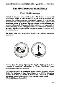
Fig. 1 Schematic illustration showing the perpendicular relations among the three planes in a system.
GLOSSARY OF TERMS
GLOSSARY OF TERMS AIR SETTING – the characteristic of some materials, such as refactory cements, core pastes, binders, and plastics to take permanent set at normal air temperatures: as opposed to thermal setting. ALLOY – A substance having metallic properties and composed of two or more chemical elements of which at least one is a metal. ANNEALING – Generally a heat treatment to soften metals; for iron and steel, consists of heating above the critical temperature followed by slow cooling usually in the furnace. ANODIZING - To subject a metal to electrolytic action as the anode of a cell in order to coat with a protective or decorative film. “AS CAST” CONDITION – Casting without subsequent heat treatment. BACK DRAFT – Reverse taper which would prevent removal of a pattern from a mold. BENTONITE – The clay used as a binder in compound sands for the foundry for increasing both green and hot strength. BINDER – A material, other than water, added to sand to bind particles together, sometimes with the aid of heat. BLASTING – A cleaning process for metal parts by the use of tumbling or high pressure air blasting, which throws abrasive particles against the surface of the part. There are different types of blasting each using their own medium. Grit blasting utilizes irregular particles of metal. Sand blasting utilizes sand. Shot blasting utilizes steel balls. BLIND RISER – A riser that is not open to the exterior of the mold. BLISTER - A surface defect or eruption caused by expansion of gas, usually as a result of heating trapped gas within the casting, or under metal, which has been plated on the casting. BLOW HOLES - Voids or holes in a casting that may occur due to entrapped air or shrinkage during solidification of heavy sections. BLOWHOLE – The presence of gas trapped in a mold during solidification causing smooth irregularly shaped cavities in the casting.
For more information or a competitive quote please contact:
TOM CLARK McCann Sales, Inc. Ph: 207-439-3747 E-mail:
[email protected]