8th International Conference on Management of Innovative Technologies MIT 2005
Selection of optimal EDM machining parameters for the given machining surface J. Valentinčič, D. Kušer, S. Smrkolj, M. Junkar University of Ljubljana, Faculty of Mechanical Engineering, Slovenia
Abstract To achieve high removal rate and low electrode wear when roughing by the sinking electrical discharge machining process (EDM), appropriate average surface power density is required in the gap between the workpiece and the electrode, i.e. rough machining parameters have to be tuned to the machining surface. Since machining surface varies with the depth of machining, the rough machining parameters have to be selected on-line to obtain appropriate average surface power density in the gap. The systems for on-line selection of the rough machining parameters of EDM process presented in the literature either have hardly acceptable disadvantages or they are very complex. Thus, a simple solution could be a significant step towards better automation of the EDM rough machining and micro electrical discharge machining (MEDM). In this paper, a system for on-line selection of the machining parameters according to the given machining surface is presented. The selection of the machining parameters is based on the acquisition of only one process attribute, i.e. the percentage of short-circuit discharges, which is significant improvement comparing to known systems. Keywords: electrical discharge machining, monitoring, machining parameters, process attributes, rough machining.
1
Introduction
Sinking electrical discharge machining (EDM) and wire electrical discharge machining (WEDM) are most commonly used technologies in tool production. EDM is a relatively slow machining process and it usually requires an electrode that is made specially for machining of a given product. The shape of the electrode is mapped into the shape of the cavity in the tool. The advantage of EDM is the ability to produce small, even micro features. The EDM process is used mostly for making moulds whereas WEDM is used for precise contour cutting. The electrode in WEDM is a wire and its trajectory defines the contour of the cut. Nowadays, research on the EDM process is mainly focused on micro machining [1] and improving surface roughness [2]. However, there are still attempts of improving the EDM process by tuning a vast variety of machining parameters for optimal machining [3,4]. Most of the EDM machine producers present on the world market have solved the problem of the gap contamination by employing various monitoring systems, different flushing methods and anti-arc systems, but only few of them have solved the problem of controlling the rough machining parameters when the machining surface varies during the machining.
MIT 2005
In the case of roughing, when the quality of the surface can be neglected, it is necessary to obtain optimal average electric power (further referred as optimal power) in the gap between the electrode and the workpiece to achieve the highest material removal rate. The average electric power (further referred as power) in the gap is determined by the machining parameters that are set on the EDM machine. Optimal power depends on the eroding surface size (Figure 1), which is a projection of the machining surface, i.e. the surface between the workpiece and the electrode, to the plane perpendicular to the machining direction [5]. Many approaches have been described in the literature and patented on the EDM and WEDM processes for on-line selection of the rough machining parameters. The systems based on the capacitance or the conductivity of the gap [6-8] are very sensitive to the contamination of the gap between the workpiece and the electrode. But the main drawback is that both, capacitance and conductivity reflect the size of the machining surface and not the size of the eroding surface.
217
22nd – 24th September 2005, Fiesa, Slovenia
Figure 1 The eroding surface is a projection of the machining surface of the electrode to the plane perpendicular to the machining direction. The eroding surface size can be determined by considering the machining parameters and the progress of the electrode into the workpiece. The machining parameters define the discharge energy and thus the material removal rate. The larger the eroding surfaces the slower the progress of the electrode into the workpiece, and vice versa. Empirical models of the WEDM process applied to determine the eroding surface size according to the material removal rate and the progress of the electrode [9-11] have a long reaction time to the variation of the eroding surface size. This is a drawback, especially when the thickness of the workpiece does not vary gradually, i.e. when the eroding surface size increases or decreases in steps. Better results were achieved with analytical [12,13] and non-parametric models [14]. Empirical models were also built on the EDM process [1517]. Long reaction time to the eroding surface size variations is not so crucial in the EDM process as it is in the case of the WEDM process where wire breakage can occur. According to the results presented in the literature, analytical and nonparametric models achieve the best performance in determining the eroding surface size. In this paper, a different approach is presented. According to our previous researches [18], the voltage and current signals in the gap are enough informative to on-line select the appropriate set of machining parameters for the current machining surface. It was found that the percentage of short-circuit discharges calculated on the voltage and current signals in the gap are enough informative to determine the appropriate set of machining parameters, which produces the optimal surface power in the gap. Thus, the algorithm for selection of the appropriate set of machining parameters was build. The input of the algorithm is only the percentage of short-circuit discharges. 218
2
Process description
2.1
Overview
EDM is a machining technique through which the surface of a metal workpiece is formed by discharges occurring in the gap between the tool, which serves as an electrode, and the workpiece. The gap is flushed by the third interface element, the dielectric fluid. The process consists of numerous randomly ignited monodischarges. During the discharge, the plasma channel is formed as the current conductor and heat generator. On the spot of discharge, a crater is formed. The size of a crater is determined by the discharge energy, which can be set on the machine by setting the discharge current and the discharge duration; the discharge voltage is always around 25 V. The material removal rate is determined by the crater size and the frequency of crater generation, i.e. discharge energy and the frequency of discharges. The latter is influenced by the discharge duration and the pulse interval between two discharges. At given discharge current there exists the optimal discharge duration [19,20] and the pulse interval should be long enough to complete deionisation in the gap. Thus, there exists an optimal combination of the machining parameter values to achieve, for instance, certain surface roughness of the workpiece. The gap distance between the electrode and the workpiece is controlled by a servo system. In a closed loop, the average voltage in the gap is compared to the reference voltage set on the machine: if average voltage is greater than reference voltage the gap is reduced by moving the electrode closer to the workpiece and vice versa. In the case of stable EDM machining, the average voltage equals the reference voltage during the machining. Expressed in other words, the gap distance is nearly constant during the machining: the electrode slowly progresses into the workpiece as the workpiece material is removed. When gap conditions cause the variation of the average voltage value, the servo system is changing the gap distance to achieve equal average and reference voltage and the machining process is unstable. Thus, the required but not satisfactory condition for stable machining process is an appropriate reference voltage value set on the machine. The machining parameters define the process performances. Incomplete deionisation of the fluid caused by too short pulse interval, for example, results in the occurrence of the stationary-located (arc) discharges, which are harmful to the workpiece surface. Consequently,
MIT 2005
8th International Conference on Management of Innovative Technologies MIT 2005
the process becomes unstable. The same result is obtained when the gap is too contaminated by the removed particles, thus appropriate flushing of the gap has to be applied during the machining process. Some of the parameters to establish satisfactory gap conditions are the parameters of the jump of the electrode. When the jump occurs, the electrode moves away from the workpiece, the machining process is interrupted due to the wide gap between the workpiece and the gap is flushed by the fresh dielectric. Usually, the electrode jump is applied periodically by setting the height and the frequency of the jump. Other parameters involved in maintaining appropriate gap conditions are out of the scope of this paper. To gain the information on the process performances during the machining, the machining process has to be monitored on-line. Most often, the voltage signal in the gap is used to monitor the process. The discharges can be identified on the voltage signal and basically four types of discharges are distinguished [21]. Many classification systems were presented in the literature [22-26]. One of them was even able to distinguish more than 10 types of discharges. In our case, five discharge types are distinguished (Figure 2). Free discharges (A) are voltage pulses without the discharge in the gap (the current equals 0). Normal discharges (B) are the most desirable since they achieve the highest material removal rate at the least electrode wear. Stationary-located arc discharges (C1) reflect high contamination of the gap with the removed particles and are not wanted since they damage the workpiece surface. The interrupted-arcs (C2) appear when the machine controller interrupts the electric current in the gap to prevent the damaging of the workpiece surface due to the high percentage of arc (C1) discharges. Short-circuit (D) discharges appear in the case of no current resistance in the gap and are causing high electrode wear. Arc, interrupted-arc and short-circuit discharges are treated as harmful discharges, since they increase the electrode wear and decrease the material removal rate [23,26-28].
2.2
Problem description
The EDM process stability is measured by the proportion of harmful discharges in the gap between the workpiece and the electrode. The process is more stable in the case of lower proportion of harmful discharges. If assuming the appropriate reference voltage of the servo system, there are two causes for unstable EDM process, namely the gap contamination with discharge products and too high power in the gap for the given eroding surface size. The latter is the topic of the present research. MIT 2005
Figure 2 Five types of discharges as noticed on the voltage signal in the gap The power in the gap is defined by the equation
P = u ⋅i
(1)
where u is the average voltage in the gap and i is the average current in the gap. The material removal rate and the surface roughness increase with increased power in the gap. When rough machining is performed, the material removal rate should be as high as possible, while the achieved surface roughness is not important. The highest material removal rate is achieved in the case of the highest power in the gap at which the machining process is still stable. This is the optimal power in the gap for roughing. The power in the gap depends on the machining parameters set on the machine and they should be tuned to the eroding surface size to obtain the optimal power in the gap [5,12]. The optimal power in the gap Popt is calculated by the equation
Popt = pb ⋅ A ,
(2)
where pb is the boundary average surface power density (further referred as (boundary power density) and A is the eroding surface size. The boundary power density is the power density at which the machining process is on the edge of stability. Increasing the average surface power density (further referred as power density) p beyond the boundary power density pb causes 219
22nd – 24th September 2005, Fiesa, Slovenia
unstable machining process, and thus lower material removal rate and higher electrode wear (Figure 3). Stable EDM process is achieved when the power density p is less than 4 W/mm2. At constant eroding surface size A1, the material removal rate increases by increasing surface current density until the boundary power density is reached. Higher power density causes unstable machining process and the material removal rate decreases. When greater eroding surface is employed (A2), the higher power is needed to reach the boundary power density, thus the material removal rate is higher compared to the material removal rate at smaller eroding surface (A1).
Figure 3 The material removal rate Vω versus the power density p for two eroding surface sizes However, in the literature, the boundary average surface current density is given rather then boundary average surface power density and it is stated that stable EDM process is achieved when the average surface current density is less than 0.1 A [29,30]. The explanation is the following. Voltage and current in the gap define the electric power in the gap (Eq. 1). Since the discharge voltage is nearly constant at all machining parameters, the power in the gap depends only on the setting of the discharge current in the gap. Note that during the pulse interval both current and power in the gap are equal to zero. As stated before, the machining parameters have to be tuned to the eroding surface size. When the eroding surface size varies during the machining, the machining parameters have to be determined on-line. Thus, it is necessary to monitor the appropriate process quantities z. The evaluation of the process quantities is a key to gain suitable process attributes x for selection of the optimal rough machining parameters. The process attributes are the inputs into the model for the selection of the optimal rough machining parameters (Figure 4).
220
Figure 4 On-line selection of the roughing machining parameters of the EDM process The models presented in the literature (Section 1) are either not enough precise, e.g. models based on detection of the capacity or conductivity in the gap, or too complex, e.g. empirical, analytical and non-parametric models, which require monitoring of many process quantities and evaluation of even more process attributes. Preliminary studies done by some of the authors of this paper showed that voltage and current signals in the gap reflect the power density in the gap [31,32]. A system based on monitoring only the voltage and/or current signal in the gap could be much simpler to build and to implement on the EDM machine compared to the systems presented in the literature. It was found [18] that the percentage of short-circuit discharges calculated on the voltage and current signals in the gap could be enough informative to determine the appropriate machining parameters that obtain the optimal power density in the gap. Since it satisfactory to monitor only one process attribute the model has only one input and one output. In such case the model is simplified into a single rule based on the value of the input. But in such way one can only determine if the power density in the gap is greater then the boundary power density. Thus, the algorithm is needed to find the optimal set of machining parameters. And the only input form the process to the algorithm is the percentage of short-circuit discharges.
MIT 2005
8th International Conference on Management of Innovative Technologies MIT 2005
3
Experimental setup
The experiments were performed on IT E 200M-E machine made by IT Elektronika, where hardened steel was machined by copper electrodes. The algorithm was selecting between 24 predefined sets of machining parameters, which are given in Table 1. The sets are arranged according to the power they obtain in the gap. The set of machining parameters that obtain the lowest power in the gap has No. 1 and the set of machining parameters that obtain the highest power in the gap has No. 24. The open voltage was constant for all sets and was set to 280 V. The jump of the electrode was set to height of 3 mm and the frequency of jumps was set to 0.2 Hz. The rest of machining parameters, such as size of the gap and servo system response time were constant for all sets, too. Table 1: The database of the predefined machining parameters High Pulse-on Pulse-off Working voltage Set time time current No. current [µs] [µs] [A] [A] 1 2 2 11 11 2 2 2 11 5 3 2 2 11 4 4 3 2 12 6 5 5 2 14 12 6 6 2 17 16 7 4 2 14 6 8 5 2 16 7 9 1 15 16 6 10 9 1 19 17 11 6 2 17 7 12 5 14 19 16 13 8 13 23 20 14 12 2 23 21 15 9 1 19 8 16 12 13 26 22 17 8 13 23 12 18 12 2 23 13 19 19 13 28 25 20 16 2 26 13 21 29 13 30 27 22 23 2 28 16 23 33 2 30 16 24 19 13 28 13 During the machining, the contamination of the gap was reduced to the minimum by thorough flushing of the gap. For this purpose external flushing by fresh dielectric with three
MIT 2005
single-jet nozzles and the periodical jump of the electrode were applied. The experiments were performed by the electrode given in Figure 5. The given shape of the electrode was selected in order to test various changes of the eroding surface size: there are features of conical shapes with variing inclination angles and one cilindrical feature. The depth of machining was 8 mm.
Figure 5 The drawing of the electrode In first experiment, the set of machining parameters that obtain the highest power in the gap, i.e. the set No. 24 was used to machine the whole feature. In the second experiment the set of machining parameters that obtain the lowest power, i.e. set No. 1 was used to machine the whole feature. These are the reference experiments to compare performance of the system for on-line selection of the machining parameters. In the third experiment, the set of machining parameters was determined by the system for on-line selection of the machining parameters, thus the machining parameters were not constant during the machining of the feature. To evaluate the experiments, the machining time, the difference in the mass of the electrode and the shapes of the electrode after machining were compared for the three experiments. The system for on-line selection of the machining parameters consists of the signal analyzer and the algorithm for selection of the machining parameters. The voltage and the current signals in the gap were acquired by the measuring system presented in Fig. 6 with a sample rate of 83.3 kHz. To establish the beginnings and endings of the discharges, the signal from the generator was used. The signals were acquired immediately after the jump of the electrode and were stored into data files for further evaluation. First 300 discharges on the signals were neglected to avoid disturbances at the beginning of the machining 221
22nd – 24th September 2005, Fiesa, Slovenia
after the jump was performed. The percentage of short-circuit discharges was calculated on 1000 discharges by the software developed with the purpose for the signal evaluation. The calculated percentage of the short circuit discharges the only input to the algorithm that selects the optimal set of the machining parameters.
4
Algorithm
The algorithm to obtain the optimal power in the gap based on the percentage of short-circuit discharges has been developed. When the optimal power in the gap is obtained, the best material removal rate at the lowest electrode wear is achieved. The algorithm works on developing platform, thus it is relatively slow. Duration of one cycle of the algorithm is approximately one minute. When the algorithm is ready for industrial use the time for one cycle will be less than a second. The algorithm works in two modes. In the first mode, the machining parameters that obtain lower power in the gap are selected when the percentage of short-circuit discharges is too high. In the second mode, the machining parameters that obtain higher power in the gap are selected when the percentage of short-circuit discharges is not significant. The algorithm (Figure 6) works as follows. First, the initial machining parameters are selected from Table 1 by an operator and the machining process starts. Machining is performed until a stop condition is reached; the required depth of machining is achieved. During machining the percentage of short-circuit discharges D is defined by the analyzer. The percentage is calculated for each of the three signals acquired consequently. Mode 1: If the minimum percentage of short-circuit discharges min(D) exceeds the critical value Dkr, which is an internal parameter of the algorithm, the set of machining parameters with lower power (i=i-1) is selected. Mode 2: If the minimal percentage of short-circuit discharges min(D) does not exceed critical value Dkr the power in the gap is either optimal or even to small to attain the highest material removal rate. To achive the optimal power in the gap and thus the highest material removal rate, the algorithm selectes the set of machining parameters with the higher power (i=i+1) 222
Figure 6 The block scheme of the algorithm When the optimal set of machining parameters is employed, the algorithm selects the set of machining parameters with higher power in the gap since the percentage of short-circuit discharges is less than Dkr. But the new set achieves too high power in the gap—percentage of short-circuit discharges is more than Dkr—and immediately the set with lower power in the gap is selected. In the case of constant eroding surface size, the algorithm would constantly switch the machining process out of the optimal area. Thus, the selection of the machining parameters with the higher power in the gap (i=i+1) is possible only when min(D)Dkr.
Table 2 The results of experiments Experiment
5
Results and discussion
As showen in Table 2, there is a big difference in machining time between set No. 1 and set No. 26. The machining time with the set No. 1 is too long to be applied for machining the whole feature. In the case of machining with the set No. 24, the roundness at the end of the electrode (figure in Table 2) is much bigger than in the case of machining with the set No. 1 or when algorithm was applied. It indicates that the set No 24 should not be used to machine the whole feature. Machining by using the algorithm was almost as fast as the machining with the set No. 24 and the wear of the electrode was almost as good as when machining with set No. 1—the algorithm was able to optimize the machining. Since the analyzer and the algorithm are built on the developing platform, the algorithm could not responde fast enought to the change of the surfice. It takes to much time to analyze the acquired signals and thus the selection of the appropriate set of machining parameters was too slow. Since the industrial application will be much faster, the results will be even better.
MIT 2005
Electrode wear [g]
Set No. 24
1812
0.03
Set No. 1
21600
0.00
Algorithm
2054
0.02
6
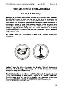
Figure 7 The percentage of short circuit discharges when the eroding surface size was constant: A=28 mm2
Machining time [s]
Shape of the electrode after machining
Conclusions
According to the results of this study, the following conclusions can be drawn: • The percentage of short-circuit discharges significantly determines the situation when the power density in the gap is greater than the boundary power density. Thus, the model is reduced into one simple rule. • According to the percentage of shortcircuit discharges, only too high power in the gap can be determined. To find the optimal machining parameters, the algorithm has to be applied, which periodically tests the machining parameters that obtain slightly higher power in the gap. If the newly selected machining parameters do not cause too high percentage of short-circuit discharges, they are better than former one and they will be used for further machining. • The algorithm is needed to enable the online selection of the optimal machining parameters in order to obtain optimal power in the gap and thus the highest material removal rate at still acceptable electrode wear. In future, the developed algorithm will be integrated into the microprocessor and will be used as a module of the machine controller.
Acknowledgment The authors would like to thank the 4m Network of Excellence for financially supporting this research and IT Elektronika for financial support and for the provided technical information on the EDM machine applied in the experiments.
223
22nd – 24th September 2005, Fiesa, Slovenia
References [1]
[2]
[3]
[4]
[5]
[6] [7] [8]
[9] [10] [11] [12]
[13]
[14]
[15]
224
B. H. Yan, A. C. Wang, C. Y. Huang, F. Y. Huang: Study of precision micro-holes in borosilicate glass using micro EDM combined with micro ultrasonic vibration machining. International Journal of Machine Tools and Manufacture 42(10) (2002) pp.1105-1112. K.M. Tsai, P.J. Wang: Predictions on surface finish in electrical discharge machining based upon neural network models. International Journal of Machine Tools and Manufacture 41(10) (2001) pp. 1385-1403. M. Junkar, J. Valentinčič: Towards intelligent control of electrical discharge machining. Manufacturing Systems, (Aachen, 1999) 29(5) pp. 453-457. A. Behrens, J. Ginzel: An open numerical control architecture for electro-discharge machining. Proceedings of the 13th International Symposium for Electromachining (ISEM 13) 1 (Bilbao, Spain, 2001) pp. 161-171. J. Valentinčič: A model of EDM process parameter selection upon the size of eroding surface. Ph.D. Thesis (in Slovene), (University of Ljubljana, Faculty of Mechanical Engineering, 2003). I. Kyoshi: Feeder for electrical discharge machining. Patent JP 57138544 A, (1982). T. Itoh: EDM apparatus current efficiency technique. Patent US 5,276,302, (1994). T. Itoh: Method and apparatus for sink-type electrical discharge machining with control of pyrographite bildup. Patent US 3,369,239, (1994). H. Obara: Wire-cut electrical discharge machine. Patent US 4,510,367, (1985). Y. Nakayama: Wire electrical discharge machine and method of use thereof. Patent US 5,243,166, (1993). Y. Ishibashi, A. Komori: Wire electric discharge machine having alterable discharge period. Patent US 5,362,936, (1994). K.P. Rajurkar, W.M. Wang, W.S. Zhao: WEDM adaptive control with a multiple input model for identification of workpiece heigh. Annals of the CIRP, 47(1) (1997), pp. 147-150. K.P Rajurkar, W.M. Wang, J.A. McGeough: WEDM identification and adaptive control for variable height components. Annals of the CIRP, 43(1) (1994), pp. 199-202. Y.S. Liao, M.T. Yan, C.C. Chang: A neural network approach for the on-line estimation of workpiece height in WEDM. Journal of Materials Processing Technology, 121(2-3) (2002), pp. 252-258. J.M. Dehmer: Prozeßführung beim funkenerosiven Senken durch adaptive Spaltweitenregelung und Steuerung der Erosionsimpulse. Fortscritt-Berichte VDI Reihe 2, VDI Verlag, WZL Produktionstechnik, No. 224 (Düsseldorf, 1992).
[16]
[17]
[18]
[19]
[20]
[21] [22]
[23] [24]
[25]
[26] [27]
[28]
[29]
G. Wollenberg, H.P. Schulze, A. Grisch: Online determination of the working area on Sinking EDM. EDM Technology, EDM Technology Transfer (1996), pp. 7-13. H.P. Schulze, G. Wollenberg, M. Luter: Face measuring systems for parameter control of electrical discharge machining. Proceedings of the 2nd International Conference on Machining and Measurement of Sculptured Surfaces (Krakow, 2000), pp. 295-304. J. Valentinčič, B. Filipič, M. Junkar: Machine learning induction of a model for on-line parameter selection in the EDM rough machining. International Journal of Machine Tools and Manufacture, To be published. D.D. DiBitonto, P.T. Eubank, M.R. Patel, M.A. Barrufet: Theoretical models of the electrical discharge machining process. I. A simple cathode erosion model. Journal of Applied Physics, 66(9) (1989), pp. 4095-4103. M.R. Patel, M.A. Barrufet, P.T. Eubank, D.D. DiBitonto: Theoretical models of the electrical discharge machining process. II. A simple anode erosionModel. Journal of Applied Physics, 66(9) (1989), pp. 4104-411. CIRP, Scientific technical committee E: Summary specifications of pulse analysers for spark-erosion machining. (1979). Y.S. Tarng, C.M. Tseng, L.K. Chung: A fuzzy pulse discriminating system for electrical discharge machining. International Journal of Machine Tools and Manufacture, 37(4) (1997), pp 511-522. V. Garbajs: Statistical model for an adaptive control of EDM-process. Annals of the CIRP,34(1) (1985), pp. 499-502. K.P. Rajurkar, W.M. Wang: Improvement in EDM surface roughness and other performances with an R.F control System. Proceedings of the 6th International Symposium for Electromachining (ISEM 6), (Magdeburg, 1992), pp. 121-135. S.F. Yu, B.Y. Lee, W.S. Lin: Waveform monitoring of electric discharge machining by wavelet transform. International Journal of Advanced Manufacturing Technology, 17(2001), pp. 339-343. D.F. Dauw: Advanced pulse discriminating system for EDM process analysis and control. Annals of the CIRP, 32(1) (1983), pp. 541-539. M.S. Albinski, A. Liebeskind: Characteristics of the process of electrical discharge machining. Proceedings of the 6th International Symposium for Electromachining (ISEM 6), (Krakow, Poland, 1980), pp. 88-96. M. Weck, J.M Dehmer: Analysis and adaptive control of EDM sinking process using the ignition delay time and fall timeas parameter. Annals of the CIRP, 41(1) (1992), pp. 243-246. J.P. Kruth, B. Lauwers, W. Clappaert: A study of EDM pocketing. Proceedings of the 1Oth International Symposium for Electromachining (ISEM 10), (Magdeburg, 1992), pp. 121-135. MIT 2005
8th International Conference on Management of Innovative Technologies MIT 2005
[30]
[31]
[32]
MIT 2005
H.P. Schulze, G. Wollenberg, G. Steinmetz: Stability of the EDM-Sinking Process. Proceedings of the l2th International Symposium for Electromachining (ISEM 12), (Aachen, VDI-Verlag Diisseldorf, 1998), pp. 215-223. J. Valentinčič, M. Junkar: A Model for detection of the eroding surface based on discharge parameters. International Journal of Machine Tools and Manufacture, 44(2-3) (2004), pp. 175-181. J. Valentinčič, M. Junkar: On-line selection of rough machining parameters. Journal of Materials Processing Tech., 149(1-3) (2004), pp. 256-262.
225
22nd – 24th September 2005, Fiesa, Slovenia
226
MIT 2005