JLMN-Journal of Laser Micro/Nanoengineering Vol. 7, No. 1, 2012
Blue Light Plasma Emission During LIBWE Using 532 nm Q-switched Nanosecond Laser Ji-Yen Cheng1,2,3,*, Mansoureh Z. Mousavi1,4,5, Chun-Ying Wu1,2, Hsieh-Fu Tsai1,3 1- Research Center for Applied Sciences, Academia Sinica Taiwan, 128 Sec.2 Academia Rd. Taipei City 11529, Taiwan
[email protected] 2- Department of Mechanical and Mechantronic Engineering, National Taiwan Ocean University 3- Institute of Biophotonics, National Yang-Ming University 4- Department of Chemistry, National Taiwan University 5- Nano Science and Technology Program, Taiwan International Graduate Program, Academia Sinica Taiwan Blue light (360 nm ~ 500 nm) emission from the glass/liquid interface was observed during the etching using a green (λ = 532 nm) nanosecond Q-switched laser. An organic dye, Oil-Red-O, dissolved in p-xylene was used for laser induced backside wet etching of borosilicate glass using the visible light laser (visible-LIBWE). The blue light emission was confirmed to accompany the etching process. The UV-visible spectrum consists of characteristic peaks of metals, which are the components of the glass material. The maximal emission intensity occurs when the laser focusing is at the glass/liquid interface. The threshold of the LIBWE etching is comparable to that of the occurrence of the blue light emission. We concluded that the emission is the plasma emission of the etched glass. By measuring the plasma emission, the occurrence of the etching and the crack formation in the glass can be monitored in real-time. DOI:10.2961/jlmn.2012.01.0017
Keywords: visible LIBWE, microfabrication, plasma, nanosecond laser, 532 nm Q-switched laser than that of soda lime glass (724 ºC). Softening point is the temperature at which the glass may deform. It is defined as the temperature when the viscosity of the glass is 107.6 poise. Since the report of visible-LIBWE(1), there has been no new report of other suitable dye for the process. There is need to test the feasibility of using other dyes as the laser energy absorber. An existing difficulty in carrying out direct-writing LIBWE [9, 10, 13, 18] is the correct focusing at the glass/liquid interface. For visible LIBWE, the concentration of the laser absorber is so high that visible light is mostly absorbed. Therefore, under an optical microscope it is difficult to visually focus the laser beam at the glass/liquid surface when the absorber is put in contact with the glass substrate. In turn, the occurrence of the etching can not be observed in real-time under the microscope. Therefore, there is a need to have a method to aid the correct focusing and to monitor the etching process in realtime. Another problem in LIBWE is that during continuous etching, the glass/liquid interface moves away from the original position when a dip or trench is formed by the etching. Therefore there is a need to carry out real-time focusing at the glass/liquid interface. In this work, by using a new absorber, Oil-Red-O, that has high solubility, we tried the etching of borosilicate glass[19]. During the etching of borosilicate using a visible light (532 nm) laser, blue light emission accompanying the etching process was observed. The source and cause of the
1. Introduction Since the invention of laser induced backside wet etching (LIBWE) [1, 2], several types of UV lasers have been utilized including excimer lasers[1, 3-7], hybrid feedbackdistributed dye/excimer laser [8], and Q-switched solid state lasers [9-12]. LIBWE process is very suitable for the fabrication of micro structures on the surface of transparent substrate. It has been applied for the fabrication of glass microfluidic channel [9], micro- and sub-micrometer structure [10] and optical components [2, 11, 12]. More recently visible laser source [9, 13] and near IR laser source [14] have also been utilized for the LIBWE process. Appling the LIBWE using a visible laser has the advantage of having lower setup cost [9, 13, 15, 16]. In addition, using visible LIBWE allows the machining of optical materials that are non-transparent to UV light, e.g. soda lime and Zerodur. The optical alignment of the visible LIBWE is also easier than that for using a UV laser. Previously we have demonstrated the use of a 532 nm green laser for successful LIBWE on soda lime glass[13]. The previous study utilizes a red dye, Rose Bengal, as the laser energy absorber. Because of the low solubility in the organic solvent, the etching threshold is relatively high compared to the UV LIBWE. In addition, the etching of borosilicate glass using Rose Bengal has not been successful. Borosilicate glass is commonly used for laboratory glassware and is more chemically resistant than soda lime. It also has higher softening point (825 ºC, Schott, [17]) 87
JLMN-Journal of Laser Micro/Nanoengineering Vol. 7, No. 1, 2012
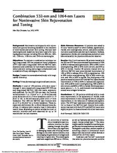
Fig. 1 Setup of the LIBWE experiment using an inverted microscope (IX71) and the layout of the spectrum detection setup. The liquid chamber is put on top of the X-Y stage. The molecular structure of ORO is shown in the lower right part.
emission was studied in this work. The emission was shown to be very helpful for the real-time focusing adjustment for the LIBWE process. We demonstrate in this work that the blue light emission can be used for focus alignment and for determining etching threshold of the visibleLIBWE.
The glass used for etching was borosilicate slide from Assistent (Glaswarenfabrik Karl Hecht GmbH&Co KG). The slides were cut into strips to fit a home-built liquid chamber that was used to hold the dye solution (Fig. 1). A 100 μm spacer was used in the liquid chamber to allow light transmission for the measurement of the absorption spectrum of the sORO solution using a spectrometer (Ocean Optics, USB2000). For the LIBWE experiments, the spacer thickness is 2 mm.
2. Experiments 2.1 Reagents Oil-Red-O (ORO, MW 408.49 , Sigma, No. O-0625) was dissolved in p-xylene (99.9 %, Tedia, XR-2248). Saturated Oil-Red-O in p-xylene (abbreviated as sORO) was used for the LIBWE experiments. The concentration of the sORO was determined spectrally by comparing to the measured absorbance from the literature (molar extinction coefficient ε ≈ 29,600 M-1cm-1 [20]). For the measurement of the concentration, an optical cell with 100 μm light path was used to hold the sORO which is 100 X diluted from the saturate solution. The absorbance was measured to be 0.194. The absorbance, A, is defined as A = log (P-in/P-out), where P-in is the incident light intensity and P-out is the light intensity transmitted through the sample[21]. The concentration of the sORO was then calculated by Beer’s law (A = εbC, where ε is the molar extinction coefficient, b is the light path through the sample in cm and C is the sample concentration in M) to be about 66 mM. For comparison, RB has similar extinction coefficient of 25,600 cm1 -1 M but its solubility in organic solvent (acetone) is only 1.2 mM[9].
2.2 Optical Setup As shown in Fig. 1, a 532 nm nanosecond Q-switched laser (Ekspla, NL202, modified to output only 532 nm light) was used in this study. The pulse duration is ~15 ns. The repetition rate is 1000 Hz. Average power of 3 mW to 20 mW was used in this study. The corresponding pulse energy was 3 μJ to 20 μJ. The laser beam was first expanded by 10 times and then directed into an inverted microscope (Olympus, IX71). The expanded beam size (1/e2 width) was measured to be 9.5 mm. The profile of the expanded laser beam was measured by a linear CCD (Thorlabs, LC1USB) and then fitted by Gaussian distribution function. The laser beam was reflected by a dichroic mirror (DM, XF2012, Omega Optical) and then focused at the first glass/liquid interface from bottom to up by a 50 mm singlet lens. The DM reflects the 532 nm laser light but allows the transmission of 380 nm to 470 nm, and 540 nm to 850 nm. The blue light emission from the glass/liquid interface could be observed using the DM but the spectrum is dis88
JLMN-Journal of Laser Micro/Nanoengineering Vol. 7, No. 1, 2012
laser pulses, in nm/pulse) was calculated using the following equation [9, 18].
torted by the DM. For spectrum measurement, a beam splitter (XF121, Omega Optical) instead of a DM was used. The beam splitter has 50 % transmission in 400 nm to 700 nm and > 50 % transmission in 330 nm to 400 nm. The blue light emission spectrum could be correctly measured using the beam splitter. The focused beam size was calculated by the following equation [18, 22] to be 5.6 μm.
Re tch =
D × 1000 , eq.(3) (d 0 / V ) × n × f
, where D (in μm) is the etched depth; V (in μm/sec) is the sweeping speed of the laser beam; d0 (in μm) is the focused beam size; n is beam pass number, and f is the laser repetition rate.
d0 ≈ (2Fλ) / di eq.(1)
(a)
where d0 represents the focused beam size; F is the focal length; λ is the laser light wavelength, and di is the initial laser beam size (= 9.5 mm in this study). The depth of focus (DOF)was calculated to be 38 μm according to the following equation [9, 22]:
DOF = 2 Z =
8λ F π di
( ) (ωω( z) ) 2
2
− 1 , eq.(2)
0
where Z, F and di are axial distance from beam waist, lens focal length, and laser spot diameter before focusing, respectively. F=50 mm and di= 9.5 mm in the current setup. The factor
ω ( z) ω0
(b)
denotes the ratio of defocused beam size
(ω(z)) and focal beam waist (ω0). Z is Rayleigh length when ω(z) = 2 ω0. The DOF is large enough for correct focusing when the laser beam scans across the glass substrate. 2.3 LIBWE process The glass and the dye solution (i.e. the absorber) were held by the liquid chamber, as shown in Fig. 1. The chamber was fixed on a computer-controlled X-Y stage. The LIBWE was carried out by moving the stage at speed of 0.5 mm/sec while the laser was focused at the glass/liquid interface. A trench could thus be fabricated. In order to deepen the trenches for correct depth measurement, each trench was scanned for 2 to 24 times. Each scan is 15 mm long. Because the high concentration of the absorber solution impairs visual focal adjustment, the focusing was initially conducted before introducing the sORO into the liquid chamber. After the etching, the glass substrate was washed thoroughly by acetone to remove the concentrated ORO and then cleaned by sonication for 5 minutes in de-ionized water. The depth of the trenches were measured by a surface profiler ((Model AS-IQ, KLA-Tencor) for shallow trenches or a scanning electron microscope (SEM, Model 5136MM, TESCAN) for deep trenches. SEM is also used for observing cross-sections. The etch rate (etch depth/number of
Fig. 2 Cross-sectional profile of typical crack-free trenches in borosilicate glass etched by using sORO as the laser absorber. (a) From left to right the beam pass number are 6, 12, and 24. (b) Close-up of the deepest trench in (a). The laser fluence is 39 J/cm2 (pulse energy 9.5 μJ).
2.4 Emission spectrum analysis The emission spectra from the liquid chamber were taken by a scientific grade spectrometer (Ocean Optics QE65000). The 50/50 beam-splitter (XF121) was used to reflect the 532 nm laser beam to the glass/liquid interface. A 500 nm short-pass filter (the F in Fig.1, No. 47-287, Edmund Optics) was used to reduce the scattered laser light
89
JLMN-Journal of Laser Micro/Nanoengineering Vol. 7, No. 1, 2012
than the etching threshold (≈ 27.6 J/cm2, please see below). When the laser is instead focused at the glass/air interface using the same fluence, no emission was observed. However, when higher fluence was applied by using higher laser power and tighter focusing, a blue light emission appeared, as shown in Fig. 3(b). The spectrum is shown in Fig. 3(b). Using a 10 X objective lens (N.A. 0.25), the calculated focused beam size is ~1.4 μm and the corresponding damaging and blue emission threshold fluence is 1 kJ/cm2, which is about 40 times higher than that by LIBWE. Similarly, the lower threshold for the LIBWE process has been observed on quartz[3]. The spectrum from the glass/liquid interface seems to be a broadened analogy of that from the glass/air interface. Because the plasma is not induced in vacuum but at liquid/solid phase, significant Stark broadening is expected [25]. The similarity suggests that the two types of spectra, Fig.3 (a) and Fig.3(b), are correlated. Spectral analysis of Fig.3(b) shows that characteristic emission peaks from metal ions are present. The aluminum (Al) plasma emission has peak at 396 nm and 481 nm. The 422 nm peak corresponds to calcium (Ca). [26] Although the corresponding element is not clear, the 444 nm peak is observed in both spectra. The two elements, Al and Ca, are part of the metal components of borosilicate glass. This result suggests that the emission from the glass/liquid interface originate from the plasma during the laser etching of the glass. However, the laser fluence used in Fig.3(a) is significantly lower than that required for the plasma formation from the glass/air interface. Further test was conducted to check whether the emission from the glass/liquid interface is indeed correlated with the etching.
from the sample. The emission was then collected by an optical fiber and delivered to the spectrometer for detection. For observing the emission intensity versus the laser power, the 50/50 beam-splitter was replaced by the dichroic mirror (XF2012) in order to provide better laser beam profile. (a)
(b)
Fig. 3 (a) Spectra of the blue light emission from the glass/liquid interface observed by using different fluence of 532 nm laser. The inset shows the image of the blue light beam spot. (b) Spectra of the emission from the glass/air interface using a 10 X objective lens for the focusing. The laser fluence (pulse energy) was 1.3 kJ/cm2 (20 μJ) and 1.1 kJ/cm2 (16.6 μJ), respectively. Several concurrent peaks in both spectra are denoted.
3.2 Blue light emission intensity and focus position Additional evidence suggests that the blue light emission is correlated with the glass etching. The blue light emission decreased when the laser focus is offset from the glass/liquid interface, as shown in Fig.4. When the same laser pulse energy 14 μJ was used and the focus was shifted into the glass or the liquid bulk, the emission decreased in both positions. When the focus is in the glass bulk, the laser fluence is 57 J/cm3, which is lower than the blue emission threshold described in section 3.1. When the focus is in the sORO solution, 90 % (A = εbC = 29,600 M-1cm-1x 0.0005 cm x 66 mM ~= 1) of the laser energy is absorbed within 5 μm from the glass/liquid interface. The result indicates that with the fluence that is high enough for inducing emission at the interface, neither the glass nor the sORO alone is sufficient for generating the emission. As discussed above, the etching during the LIBWE process is achieved by the shockwave generated by the rapid evaporation of the liquid. From the result in Fig.4, it is clear that below the fluence for direct glass ablation (i.e. at glass/air interface), the blue light emission does not occur in the glass bulk or the liquid. When focusing is inside the glass bulk, the plasma emission was not observed at these fluences simply because the threshold was not exceeded. When focusing is inside the liquid, it was observed under microscope that the liquid evaporation continues to
3. RESULTS AND DISCUSSION 3.1 Etching and blue light emission Successful etching of borosilicate glass using sORO as the laser energy absorber was observed. Fig. 2 shows the cross-sectional view of typical crack-free etching on borosilicate glass surface. By scanning the laser beam for multiple passes, deep etching was achieved. It is noted that although the estimated laser beam size (1/e2) is 5.6 μm, the minimal etching width is about 8.5 μm. This is because the LIBWE process involves the generation of shockwave and high temperature [3, 23, 24] and it is the shockwave together with the raised temperature that actually etched the glass surface[3]. The shockwave propagation and the heat conduction are supposed to be isotropic so that the obtained etching width is wider than the minimal beam size. During the etching of the LIBWE process using the green laser, blue light emission originated from the laser excited glass/liquid interface was observed. The etching did not occur (observed by optical microscope, surface profiler or by SEM) if there was no blue light emission. In addition, the blue light emission was observed when the laser is focused at the interface and when the laser fluence is larger
90
JLMN-Journal of Laser Micro/Nanoengineering Vol. 7, No. 1, 2012
The traditional method (”Etching rate” in Fig.5) was carried out as follows. Trenches in the borosilicate glass surface was etched by using increasing laser fluence for each trench. The glass substrate was then detached from the liquid chamber and cleaned. The obtained trench depths were then measured after the LIBWE process. The perpulse etching rates were calculated and then plotted against the laser fluence. The minimal fluence required for the etching is the etching threshold. Because the substrate needed to be cleaned and then coated with gold (for SEM), this traditional method is an off-line method and is very time consuming. Since the plasma emission was found to correlate with the etching process, the etching threshold could be obtained by measuring the emission intensity vs. the laser fluence. Indeed, the result of the blue light emission intensity (“Blue light intensity” in Fig.5) allows us to determine the etching threshold to be 27.6 J/cm2, which is comparable to the value obtained by measuring the etching rate. However, determining the threshold by measuring the emission intensity is faster and easier than that by using the traditional method. It is also noted that the new method shows smaller data fluctuation. This is expected to provide more accurate etching threshold. In addition, Fig.5 shows the two fluence regions of the blue light intensity, the low fluence region and the high fluence region, as have been observed for sapphire and fused silica by LIBWE[4]. The two regions correspond to different etching mechanism[4]. The existence of the breaking point at about 45 J/cm2 in the etch rate-fluence graph indicates the involvement of a thin modified layer on the glass surface[23]. However, the two regions are not clearly observed due to the large data fluctuation of the depth measurement. In the reference [4], the etch rate is relatively large (up to 250 nm/pulse) so that a smooth curve is observed for the etch rate. In Fig.5, the fluctuation of etch rate does not allow us to define the two regions similar to those in the literature[4]. In summary, using the new method to determine the etching threshold is more rapid and accurate. The method may be useful for real-time monitoring of the LIBWE process.
occur, indicating the continuous generation of shockwave[3, 7]. Therefore, the blue light emission originating from the glass/liquid interface is not solely from the shockwave. It is likely that, as has been discussed in the literature, the shockwave together with the heating at the glass/liquid interface causes the etching of the glass. In addition, the existence of the metal emission peaks is in consistent with this observation. In summary, we conclude that the blue light emission is the plasma emission of the etched glass. The plasma emission is a consequence the glass etching.
Fig. 4 Intensity of the blue light emission vs. the focusing position. The position for the highest intensity coincides with the focusing position of the glass/liquid interface. The positive Z side faces toward the sORO solution. The laser pulse energy was maintained at 14 μJ.
Since the plasma emission decreases when the laser focus is moved away from the glass/liquid interface, this property is very helpful for the alignment of the light focusing. One could adjust the focal position to be at the glass/liquid interface by optimizing the plasma emission. Furthermore, the correct focusing position could then be maintained by tracing the position at which the optimal intensity occurs. This method circumvents the problem that the concentrated ORO impairs the visual focusing. 3.3 Threshold of etching and the blue light emission We compared the laser fluence threshold of the etching rate and that of the blue light emission.
3.4 Monitoring smooth etching using the plasma emission The stability of the blue light plasma emission can be used to monitor the occurrence of glass crack during the etching. When glass is smoothly etched by the LIBWE process, the plasma emission intensity was relatively stable (Fig.6). With the laser fluence of 43 J/cm2 (pulse energy 10.6 μJ), the plasma emission fluctuation is 8%, which is comparable to the stability of the laser source (5 %). When the laser fluence is too high so that the glass cracks (observed under an optical microscope after the LIBWE experiment), the plasma emission intensity fluctuates significantly. The fluctuation may originate from the laser light scattering caused by the cracked glass surface. The intensity fluctuation was quantified by the coefficient of variation (CV = standard deviation/mean) of the blue light emission intensity. Figure 6 shows a large increase in the fluctuation (CV 23 %) when fluence of 72 J/cm2 (pulse energy
Fig. 5 Comparison of the threshold of etching rate and the blue light emission. Similar etching threshold values were observed.
91
JLMN-Journal of Laser Micro/Nanoengineering Vol. 7, No. 1, 2012
17.6 μJ) was used. In essence, the fluctuation is utilized to monitor the crack formation at the glass/liquid interface. A comparison between Fig.6 and Fig. 5 indicates that the etch rate can not be increased indefinitely without causing crack formation, e.g. the case using 72 J/cm2 fluence.
[5] Zimmer, K., A. Braun, and R. Bohme, Applied surface science, 208-209 (2003) 199-204. [6] Vass, C., B. Hopp, T. Smausz, and F. Igna´cz, Thin Solid Films, 453-454 (2004) 121-126. [7] Vass, C., T. Smausz, and B. Hopp, J. Phys. D: Appl. Phys., 37 (2004) 2449–2454. [8] Bohme, R. and et al., Nanotechnology, 19 (2008) 495301. [9] Cheng, J.-Y., M.-H. Yen, and T.-H. Young, Journal of Micromechanics and Microengineering, 16 (2006) 2420-2424. [10] Niino, H., Y. Kawaguchi, T. Sato, A. Narazaki, T. Gumpenberger, and R. Kurosaki, JLMN-Journal of Laser Micro/Nanoengineering, 1 (2006) 39-43. [11] Zimmer, K. and R. Bohme, Optics and Lasers in Engineering, 43 (2005) 1349–1360. [12] Vass, C., K. Osvay, T. Véső, B. Hopp, and Z. Bor, Applied Physics A: Materials Science & Processing, 93 (2008) 69-73. [13] Cheng, J.-Y., M.-H. Yen, W.-C. Hsu, J.-H. Jhang, and T.-H. Young, Journal of Micromechanics and Microengineering, 17 (2007) 2316-2323. [14] Yen, M.-H., C.-W. Huang, W.-C. Hsu, T.-H. Young, K. Zimmer, and J.-Y. Cheng*, Applied Surface Science, 257 (2010) 87-92. [15] Cheng, J.-Y., M.-H. Yen, and T.-H. Young. in The 4th Internaional Congress on Laser Advanced Materials Processing LAMP2006. Kyoto Japan (2006). [16] Cheng, J.-Y., M.-H. Yen, W.-C. Hsu, and T.-H. Young. in The 8th International Symposium on Laser Precision Microfabrication, LPM2007. Vienna, Austria (2007). [17] Schott, http://www.schott.com. [18] Cheng, J.-Y., M.-H. Yen, C.-W. Wei, Y.-C. Chuang, and T.-H. Young, Journal of Micromechanics and Microengineering, 15 (2005) 1147-1156. [19] Cheng, J.-Y., M.Z. Mousavi, C.-Y. Wu, and H.-F. Tsai, Journal of Micromechanics and Microengineering, 21 (2011) 075019. [20] Palanuwech, J., R. Potineni, R.F. Roberts, and J.N. Coupland, Food Hydrocolloids, 17 (2003) 55-62. [21] Willard, H.H., J. Lynme L. Merritt, J.A. Dean, and J. Frank A. Settle, Instrumental Methods of Analysis. 7th ed. 1988, Belmont: Wadsworth, Inc. [22] Siegman, A.E., Lasers. 1986: University Science Books, Sausalito, California. [23] Vass, C., J. Budai, Z. Schay, and B. Hopp, JLMNJournal of Laser Micro/Nanoengineering, 5 (2010) 4347. [24] Zimmer, K., R. Böhme, M. Ehrhardt, and B. Rauschenbach, Applied Physics A, 101 (2010) 405–410. [25] Bukin, O., I. Bazarov, N. Bodin, A. Il’in, V. Tsarev, A. Maior, and E. Bol’shakova, Journal of Applied Spectroscopy, 67 (2000) 320-326. [26] Kurniawan, H., S. Nakajima, J.E. Batubara, M. Marpaung, M. Okamoto, and K. Kagawa, Applied Spectroscopy, 49 (1995) 1067-1072.
Fig. 6 More stable blue light emission was observed for the crackfree etching (left part, fluence 43 J/cm2, pulse energy 10.6 μJ) than that from the crack-generating etching (right part, fluence 72 J/cm2, pulse energy 17.6 μJ). The numbers in the parenthesis are the coefficient of variance (CV). The emission intensity was normalized against the laser intensity
4. Conclusion Oil-Red-O (ORO), which is new to the LIBWE process, was successfully used for visible LIBWE. Borosilicate glass was successfully etched using sORO. The etching of borosilicate glass was accompanied by a blue light emission. The maximal emission intensity occurs when the laser focusing is at the glass/liquid interface. The threshold of the occurrence of the blue light emission is in coincidence with that of the etching. The emission shows characteristic plasma emission peaks of metals, which are the components of the borosilicate glass. The blue light emission during the visible-LIBWE is very similar to the glass plasma emission in the air. We concluded that the blue light emission is the plasma emission of the etched glass, as consequence of the etching. By measuring the blue light plasma emission, the occurrence of the etching and the crack formation was monitored. This new method provides a rapid way to determine the etching threshold and monitoring the formation of crack during the LIBWE process. Acknowledgments and Appendixes This work is financially supported by National Science Council, Taiwan (Contract no. NSC 98-2113-M-001-013MY2) and the Academia Sinica Nano Program, Academia Sinica Taiwan. References [1] Wang, J., H. Niino, and A. Yabe, Applied physics A, 69 (1999) S271-S273. [2] Wang, J., H. Niino, and A. Yabe, Applied physics A, 68 (1999) 111-113. [3] Niino, H., Y. Yasui, X. Ding, A. Narazaki, T. Sato, Y. Kawaguchi, and A. Yabe, Journal of Photochemistry and Potobiology A:Chemistry, 158 (2003) 179-182. [4] Bohme, R., A. Braun, and K. Zimmer, Applied surface science, 186 (2002) 276-281.
(Received: June 6, 2011, Accepted: January 16, 2012)
92