®
RT6154A/B High Efficiency Single Inductor Buck-Boost Converter General Description
Features
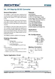
The RT6154A/B is a high efficiency single inductor BuckBoost Converter which can operate with wide input voltage such as battery which is higher or lower than the output voltage and it can supply the load current up to 4A. The maximum peak current in the switches is limited to a typical value of 5A.
z
Operates from a Single Li-ion Cell : 1.8V to 5.5V
z
Adjustable Output Voltage : 1.8V to 5.5V 3A Maximum Load Capability for V IN > 3.6V, VOUT = 3.3V Power Save Mode (PSM) for Improving Low Output Power Efficiency Fixed Frequency Operation at 2.4MHz and Synchronization Possible from 2.2MHz to 2.6MHz Up to 96% Efficiency Input Current Limit Internal Compensation RoHS Compliant and Halogen Free
z
z
z
The RT6154A/B feedback loop is internally compensated for both Buck and Boost operation and it provides seamless transition between Buck and Boost modes and optimal transient response. The RT6154A/B operates at 2.4MHz typical switching frequency in full synchronous operation.
z z z z
The RT6154A/B operates in Pulse Skipped Modulation (PSM) mode for increasing efficiency during low power RF transmission modes. The Power Save Mode can be disabled, forcing the RT6154A/B to operate at a fixed switching frequency operation at 2.4MHz. The RT6154A/ B can also be synchronized with external frequency from 2.2MHz to 2.6MHz. The RT6154A output voltage is programmable using an external resistor divider, and the RT6154B is fixed internally to 3.3V.
Applications z z z
Cellular Phones Portable Hard Disk Drives PDAs
Pin Configurations (TOP VIEW) VINA GND FB VOUT VOUT LX2 LX2
1 2 3 4 5 6 7
PGND 15
14 13 12 11 10 9 8
PGOOD PS/SYNC EN VIN VIN LX1 LX1
WDFN-14AL 4x3
Simplified Application Circuit LX1
LX2
RT6154A VIN
VOUT
VIN
VINA
Enable
EN
VOUT
FB
PGOOD
Power Good Output
PS/SYNC GND
Copyright © 2014 Richtek Technology Corporation. All rights reserved.
DS6154A/B-01 May 2014
PGND
is a registered trademark of Richtek Technology Corporation.
www.richtek.com 1
RT6154A/B Ordering Information
Marking Information
RT6154A/B
RT6154AGQW
Package Type QW : WDFN-14AL 4x3 (W-Type) Lead Plating System G : Green (Halogen Free and Pb Free)
0E= : Product Code
0E=YM DNN
YMDNN : Date Code
RT6154A Adjustable Output Voltage RT6154B Fixed 3.3V Output Voltage RT6154BGQW
Note :
0D= : Product Code
Richtek products are : `
RoHS compliant and compatible with the current require-
`
Suitable for use in SnPb or Pb-free soldering processes.
0D=YM DNN
YMDNN : Date Code
ments of IPC/JEDEC J-STD-020.
Functional Pin Description Pin No.
Pin Name
Pin Function
1
VINA
Supply Voltage Input.
2
GND
Analog Ground.
3
FB
Voltage Feedback of Adjustable Versions, must be connected to VOUT on fixed output voltage versions.
4, 5
VOUT
Buck-Boost Converter Output.
6, 7
LX2
Second Switch Node.
8, 9
LX1
First Switch Node.
10, 11
VIN
Power Input.
12
EN
Enable Control Input (1 Enabled, 0 Disabled). Must not be left open.
13
PS/SYNC
Enable/Disable Control Input for Power Save Mode (1 disabled, 0 enabled, clock signal for synchronization). Must not be left open.
14
PGOOD
Power Good Indicator Output. (1 good, 0 failure; open drain).
PGND
Power Ground. The exposed pad must be soldered to a large PCB and connected to PGND for maximum power dissipation.
15 (Exposed Pad)
Copyright © 2014 Richtek Technology Corporation. All rights reserved.
www.richtek.com 2
is a registered trademark of Richtek Technology Corporation.
DS6154A/B-01 May 2014
RT6154A/B Function Block Diagram RT6154A (Adjustable Output Voltage) LX2
LX1
VIN
VOUT
Gate DRV
VINA
OCP PWM CTRL -
EN Digital CTRL
FB
AMP +
PS/SYNC PGOOD
VREF PGND OSC
OTP
GND
UVLO
RT6154B (Fixed 3.3V Output Voltage) LX1
LX2
VIN
VOUT
Gate DRV
VINA
OCP PWM CTRL
EN
RFB1
Digital CTRL
-
AMP +
PS/SYNC
FB
RFB2
PGOOD VREF
PGND GND
OSC
OTP
Copyright © 2014 Richtek Technology Corporation. All rights reserved.
DS6154A/B-01 May 2014
UVLO
is a registered trademark of Richtek Technology Corporation.
www.richtek.com 3
RT6154A/B Operation The RT6154A/B is a synchronous current-mode switching Buck-Boost converter designed to an adjustable output voltage from an input supply that can be above, equal, or below the output voltage. The average inductor current is regulated by a fast current regulator which is controlled by a voltage control loop. The voltage error amplifier gets its feedback input from the FB pin. The output voltage of the RT6154A is adjustable, and can be set by the external divider resistor value. For the RT6154B, the output voltage is fixed at 3.3V. When VIN is greater than VOUT, the device operates in Buck mode. When VIN is lower than VOUT, the device operates in Boost mode. When VIN is close to VOUT, the RT6154A/B automatically enters Buck or Boost mode. In that case, the converter will maintain the regulation for output voltage and keep a minimum current ripple in the inductor to guarantee good performance.
Copyright © 2014 Richtek Technology Corporation. All rights reserved.
www.richtek.com 4
is a registered trademark of Richtek Technology Corporation.
DS6154A/B-01 May 2014
RT6154A/B Absolute Maximum Ratings z z z z z z z
z
z z z z
(Note 1)
VIN, VINA to GND ------------------------------------------------------------------ −0.2V to 6V VOUT to GND ----------------------------------------------------------------------- −0.2V to 6.5V EN, PS/SYNC to GND ------------------------------------------------------------ −0.2V to (PVIN + 0.2V) with 6V max. FB to PGND ------------------------------------------------------------------------- −0.2V to (PVIN + 0.2V) with 6V max. LX1 ------------------------------------------------------------------------------------- (PGND − 0.2V) to (PVIN + 0.2V) with 6V max. LX2 ------------------------------------------------------------------------------------- (PGND − 0.2V) to (PVIN + 0.2V) with 6.5V max. Power Dissipation, PD @ TA = 25°C WDFN-14AL 4x3 -------------------------------------------------------------------- 3.49W Package Thermal Resistance (Note 2) WDFN-14AL 4x3, θJA -------------------------------------------------------------- 28.6°C/W WDFN-14AL 4x3, θJC -------------------------------------------------------------- 3.2°C/W Lead Temperature (Soldering, 10 sec.) ---------------------------------------- 260°C Junction Temperature -------------------------------------------------------------- 150°C Storage Temperature Range ----------------------------------------------------- −65°C to 150°C ESD Susceptibility (Note 3) HBM (Human Body Model) ------------------------------------------------------- 2kV MM (Machine Model) -------------------------------------------------------------- 200V
Recommended Operating Conditions z z z z
(Note 4)
Input Voltage Range --------------------------------------------------------------- 1.8V to 5.5V Output Voltage Range ------------------------------------------------------------- 1.8V to 5.5V Junction Temperature Range ----------------------------------------------------- −40°C to 125°C Ambient Temperature Range ----------------------------------------------------- −40°C to 85°C
Electrical Characteristics (VIN = 3.6V, TA = 25°C, unless otherwise specified.)
Parameter
Symbol
Test Conditions
Min
Typ
Max
Unit
Under-Voltage Lockout Rising UVLO_R Threshold
1.6
1.7
1.8
V
Under-Voltage Lockout Falling Threshold
1.5
1.6
1.7
V
1.5
1.8
2.0
V
UVLO_F
Minimum Input Voltage for Start-Up FB Voltage
VFB
Force PWM (RT6154A)
0.495
0.5
0.505
V
VOUT Voltage
VOUT
Force PWM (RT6154B)
3.267
3.3
3.333
V
Shutdown Current
ISHDN
EN = 0V, PS/SYNC = 0V, PGOOD = 0V
--
0.1
1
μA
Switching Frequency
fSW
2.2
2.4
2.6
MHz
2.2
2.4
2.6
MHz
VIN = VINA = 3.6V
--
5
--
A
High-Side Switch RDS(ON)
VIN = VINA = 3.6V
--
50
--
mΩ
Low-Side Switch RDS(ON)
VIN = VINA = 3.6V
--
50
--
mΩ
Frequency Range for Synchronization Current Limit
IOC
Copyright © 2014 Richtek Technology Corporation. All rights reserved.
DS6154A/B-01 May 2014
is a registered trademark of Richtek Technology Corporation.
www.richtek.com 5
RT6154A/B Parameter
Symbol
Quiescent Current
Test Conditions
Min
Typ
Max
Unit
Non Switching, EN = VINA, SYNC = 0V
--
20
40
μA
FB Input Leakage
IFB
ADJ Mode
−1
--
1
μA
Leakage of LX1 and LX2
ILX1 ILX2
All Switch Off
--
--
5
μA
Line Regulation
ΔVOUT, LINE
FPWM
--
0.5
--
%
Load Regulation
ΔVOUT, LOAD FPWM
--
0.5
--
%
EN, PS/SYNC Logic-High Input Voltage Logic-Low
VIH
1.2
--
--
VIL
--
--
0.4
PS/SYNC Input Current
--
0.1
1
μA
EN Pull Low Resistance
--
150
--
kΩ
--
0.04
0.4
V
--
0.01
0.1
μA
PGOOD Output Low Voltage
VOUT = 3.3V, IPGOODL = 10μA
PGOOD Output Leakage Current
V
Output Over-Voltage Protection
VOUTOVP
--
6.2
--
V
Thermal Shutdown
TSD
--
160
--
°C
Thermal Shutdown Hysteresis
ΔTSD
--
30
--
°C
Note 1. Stresses beyond those listed “Absolute Maximum Ratings” may cause permanent damage to the device. These are stress ratings only, and functional operation of the device at these or any other conditions beyond those indicated in the operational sections of the specifications is not implied. Exposure to absolute maximum rating conditions may affect device reliability. Note 2. θJA is measured at TA = 25°C on a high effective thermal conductivity four-layer test board per JEDEC 51-7. θJC is measured at the exposed pad of the package. Note 3. Devices are ESD sensitive. Handling precaution is recommended. Note 4. The device is not guaranteed to function outside its operating conditions.
Copyright © 2014 Richtek Technology Corporation. All rights reserved.
www.richtek.com 6
is a registered trademark of Richtek Technology Corporation.
DS6154A/B-01 May 2014
RT6154A/B Typical Application Circuit RT6154A (Adjustable Output Voltage) L1 2.2µH 8, 9 6, 7 LX1 LX2 RT6154A 10, 11 4, 5 VOUT VIN C1 R1 20µF 1M 1 3 R3 FB VINA C3 1M R2 0.1µF 180k
VIN
Enable
12 13
EN
PGOOD
VOUT C2 100µF
Power Good Output
14
PS/SYNC GND 2
PGND 15 (Exposed Pad)
RT6154B (Fixed 3.3V Output Voltage)
L1 2.2µH 8, 9 6, 7 LX1 LX2 RT6154B 10, 11 4, 5 VOUT VIN C1 20µF 1 3 FB VINA C3 0.1µF
VIN
Enable
12 13
EN
R1 1M Power Good Output
14
PS/SYNC GND 2
Copyright © 2014 Richtek Technology Corporation. All rights reserved.
DS6154A/B-01 May 2014
PGOOD
VOUT C2 100µF
PGND 15 (Exposed Pad)
is a registered trademark of Richtek Technology Corporation.
www.richtek.com 7
RT6154A/B Typical Operating Characteristics Efficiency vs. Output Current
Efficiency vs. Output Current
100
100
90
90
VIN = 3.7V VIN = 2.8V VIN = 5V
70
VIN = 3.7V VIN = 2.8V VIN = 5V
80
Efficiency (%)
Efficiency (%)
80
60 50 40 30 20
70 60 50 40 30 20
VOUT = 3.3V Power Save Enable
10 0 0.01
0.1
1
VOUT = 3.3V Power Save Disable
10 0 0.01
10
Output Current (A)
Efficiency vs. Output Current
10
Efficiency vs. Output Current 100
90
90
VIN = 5V VIN = 3.7V VIN = 2.8V
70
VIN = 5V VIN = 3.7V VIN = 2.8V
80
Efficiency (%)
80
Efficiency (%)
1
Output Current (A)
100
60 50 40 30 20
70 60 50 40 30 20
VOUT = 4.5V Power Save Enable
10 0 0.01
0.1
1
VOUT = 4.5V Power Save Disable
10 0 0.01
10
Output Current (A)
0.1
1
10
Output Current (A)
Output Voltage vs. Output Current
Output Voltage vs. Output Current
3.40
4.60
3.35
4.55
Output Voltage (V)
Output Voltage (V)
0.1
3.30
3.25
4.50
4.45
VIN = 3.7V, VOUT = 4.5V Power Save Disable
VIN = 3.7V, VOUT = 3.3V Power Save Disable 3.20
4.40 0.01
0.1
1
Output Current (A)
Copyright © 2014 Richtek Technology Corporation. All rights reserved.
www.richtek.com 8
10
0.01
0.1
1
10
Output Current (A)
is a registered trademark of Richtek Technology Corporation.
DS6154A/B-01 May 2014
RT6154A/B Load Transient Response
Maximum Output Current vs. Input Voltage Maximum Output Current (A)1
5
4
3
I LOAD (500mA/Div)
2
VOUT (100mV/Div)
1
VOUT = 3.3V
VIN = 2.8V, ILOAD = 500mA to 1500mA
0 1.8
2.2
2.6
3
3.4
3.8
4.2
4.6
5
5.4
Time (50μs/Div)
5.8
Input Voltage (V)
Load Transient Response
Line Transient Response
I LOAD (500mA/Div) VOUT (100mV/Div) VIN = 4.2V, ILOAD = 500mA to 1500mA
VOUT (50mV/Div) VIN (1V/Div) VIN = 3V to 3.7V, ILOAD = 500mA
Time (50μs/Div)
Time (500μs/Div)
Line Transient Response
Startup After Enable
VENB (2V/Div) VOUT (2V/Div) I IN (1A/Div)
VOUT (50mV/Div) VIN (1V/Div)
VLX2 (5V/Div) VIN = 3V to 3.7V, ILOAD = 1A
Time (500μs/Div)
Copyright © 2014 Richtek Technology Corporation. All rights reserved.
DS6154A/B-01 May 2014
VIN = 1.8V, RL = 8.2Ω
Time (100μs/Div)
is a registered trademark of Richtek Technology Corporation.
www.richtek.com 9
RT6154A/B Startup After Enable
VENB (5V/Div) VOUT (2V/Div) I IN (1A/Div) VLX1 (5V/Div) VIN = 5.5V, RL = 8.2Ω
Time (100μs/Div)
Copyright © 2014 Richtek Technology Corporation. All rights reserved.
www.richtek.com 10
is a registered trademark of Richtek Technology Corporation.
DS6154A/B-01 May 2014
RT6154A/B Application Information The RT6154A/B Buck-Boost DC/DC converter can operate with wide input voltage such as battery which is higher or lower than the output voltage and it can supply the load current up to 4A. The maximum peak current in the switches is limited to a typical value of 5A. The typical operating input voltage is between 1.8V and 5.5V. The RT6154A output voltage can be set from 1.8V to 5.5V by changing the external divider resistor on the FB pin for the adjustable. The RT6154B output voltage is fixed to 3.3V. The converter feedback loop is internally compensated for both Buck and Boost operation and it provides seamless transition between Buck and Boost modes operation.
Power Good The RT6154A/B has a built-in power good function on PGOOD pin to indicate whether the output voltage is regulated properly or not. The PGOOD pin output is opendrain, so the logic function can be adjusted to any voltage level by connecting a pull-up resistor to the supply voltage. When the output voltage is regulated properly, the PGOOD pin becomes high impedance and indicates high level to the power good output. When the output voltage is regulated improperly, the PGOOD pin becomes low impedance and indicates low level to the power good output. Power-Save Mode and Synchronization
Enable
The PS/SYNC pin can be used to select different operation
The device can be enabled or disenabled by the EN pin. When the EN pin is higher than the threshold of logic high, the device starts operation with soft-start. Once the EN pin is set at low, the device will be shut down. In shutdown mode, the converter stops switching, internal control circuitry is turned off, and the load is disconnected from the input. This also means that the output voltage can drop below the input voltage during shutdown.
modes. When PS/SYNC is set low and the average inductor current gets lower then about 400mA, Power Save Mode can be enabled and used to improve efficiency.
Output Voltage Setting The RT6154A output voltage can be set from 1.8V to 5.5V by changing the external divider resistor on the FB pin. The RT6154B output voltage is fixed to 3.3V. When the adjustable output voltage version is used, the resistor divider must be connected between VOUT, FB and GND. The typical value of the voltage at the FB pin is 500mV and the RT6154A output voltage can be set from 1.8V to 5.5V. It is recommended to keep the resistor R2 value in the range of 200kΩ. From that, the value of the resistor connected between VOUT and FB, R1, depending on the needed output voltage, can be calculated as following equation : V R1 = R2 × ⎛⎜ OUT − 1⎞⎟ ⎝ VFB ⎠
Copyright © 2014 Richtek Technology Corporation. All rights reserved.
DS6154A/B-01 May 2014
At this point the converter operates with reduced switching frequency and with a minimum quiescent current to maintain high efficiency. When the load increases above the minimum forced inductor current of about 400mA, the device will automatically switch to PWM mode. The Power Save Mode can be disabled by programming the PS/SYNC high. Connecting a clock signal at PS/SYNC can force the RT6154A/B switching frequency to synchronize to the connected clock frequency. The PS/SYNC input supports standard logic thresholds and the frequency range is between 2.2MHz to 2.6MHz. Dynamic Current Limit To protect the device and the application, the peak inductor current is limited internally on the IC. At nominal operating conditions, this current limit is constant. The current limit value can be found in the electrical characteristics table. If the supply voltage at VIN drops below 2.3V, the current limit is reduced. This can happen when the input power source becomes weak. Increasing output impedance, when the batteries are almost discharged, or an additional heavy
is a registered trademark of Richtek Technology Corporation.
www.richtek.com 11
RT6154A/B pulse load is connected to the battery can cause the VIN voltage to drop. The dynamic current limit has its lowest value when reaching the minimum recommended supply voltage at VIN. Soft-Start and Short Circuit Protection After being enabled, the device starts operating. The current limit ramps up from an initial 1A following the output voltage increasing. At an output voltage of about 1.2V, the current limit is at its nominal value. If the output voltage does not increase, the current limit will not increase. There is no timer implemented. Thus, the output voltage overshoot at startup, as well as the inrush current, is kept at a minimum. The device ramps up the output voltage in a controlled manner even if a large capacitor is connected at the output. When the output voltage does not increase above 1.2V, the device assumes a short circuit at the output, and keeps the current limit low to protect itself and the application. At a short on the output during operation, the current limit also is decreased accordingly. Protection Additional protections of the RT6154A/B include current overload protection, output over-voltage clamp, and thermal shutdown. To protect the device from overheating, the device has a built-in temperature sensor which monitors the internal junction temperature. If the temperature exceeds a threshold, the device stops operating. As soon as the IC temperature decreases below the threshold with a hysteresis, it starts operating again. The built-in hysteresis is designed to avoid unstable operation at IC temperatures near the over-temperature threshold. Under-Voltage Lockout The under-voltage lockout circuit prevents the device from operating incorrectly at low input voltages. It prevents the converter from turning on the power switches under undefined conditions and prevents the battery from deep discharge. PVIN voltage must be greater than 1.7V to enable the converter. During operation, if PVIN voltage drops below 1.6V, the converter is disabled until the supply exceeds the UVLO rising threshold. The RT6154A/B automatically restarts if the input voltage recovers to the input voltage UVLO high level. Copyright © 2014 Richtek Technology Corporation. All rights reserved.
www.richtek.com 12
Inductor Selection To properly configure the Buck-Boost converter, an inductor must be connected between the LX1 and LX2 pins. To estimate the inductance value, two equations are listed as below : VOUT × ( VIN(MAX) − VOUT ) L1 > (H) f × ΔIL × VIN(MAX)
L2 >
VIN(MIN) × ( VOUT − VIN(MIN) ) f × ΔIL × VOUT
(H)
where f is the minimum switching frequency. L1 is the minimum inductor value for Buck mode operation. VIN(MAX) is the maximum input voltage. L2 is the minimum inductance for Boost mode operation. VIN(MIN) is the minimum input voltage. The recommended minimum inductor value is either L1 or L2 whichever is higher. For example, a suitable inductor value is 2.2μH for generating a 3.3V output voltage from a Li-Ion battery with the range from 2.5V to 4.2V. The recommended inductor value range is between 1.5μH and 4.7μH. In general, a higher inductor value offers better performance in high voltage conversion condition. Table 1. Inductor Suggestion
Vendor
Inductor Series
Taiyo Yuden
NRS5024T2R2NMGJ
Output Capacitor Selection The output capacitor selection determines the output voltage ripple and transient response. It is recommended to use ceramic capacitors placed as close as possible to the VOUT and GND pins of the IC. If, for any reason, the application requires the use of large capacitors which can not be placed close to the IC, using a small ceramic capacitor in parallel to the large one is recommended. This small capacitor should be placed as close as possible to the VOUT and GND pins of the IC. The output voltage ripple for a given output capacitor is expressed as follows : ΔVOUT , peak (Buck) =
VOUT × (VIN − VOUT )
VIN × 8 × L × (fOSC )2 × COUT I × (VOUT − VIN ) ΔVOUT , peak (Boost) = LOAD COUT × VOUT × fOSC
is a registered trademark of Richtek Technology Corporation.
DS6154A/B-01 May 2014
RT6154A/B
The maximum voltage of overshoot or undershoot, is inversely proportional to the value of the output capacitor. To ensure stability and excellent transient response, it is recommended to use a minimum of 100μF X7R capacitors at the output. For surface mount applications, Taiyo Yuden or TDK ceramic capacitors, X7R series Multi-layer Ceramic Capacitor is recommended. A capacitor with a value in the range of the calculated minimum should be used. This is required to maintain control loop stability. There are no additional requirements regarding minimum ESR. Low ESR capacitors should be used to minimize output voltage ripple. Larger capacitors will cause lower output voltage ripple as well as lower output voltage drop during load transients. Thermal Considerations For continuous operation, do not exceed absolute maximum junction temperature. The maximum power dissipation depends on the thermal resistance of the IC package, PCB layout, rate of surrounding airflow, and difference between junction and ambient temperature. The maximum power dissipation can be calculated by the following formula :
The maximum power dissipation depends on the operating ambient temperature for fixed T J(MAX) and thermal resistance, θJA. The derating curve in Figure 1 allows the designer to see the effect of rising ambient temperature on the maximum power dissipation. 4.0
Maximum Power Dissipation (W)1
If the RT6154A/B operates in Buck mode, the worst-case voltage ripple occurs at the highest input voltage. When the RT6154A/B operates in Boost mode, the worst-case voltage ripple occurs at the lowest input voltage.
Four-Layer PCB
3.6 3.2 2.8 2.4 2.0 1.6 1.2 0.8 0.4 0.0 0
25
50
75
100
125
Ambient Temperature (°C)
Figure 1. Derating Curve of Maximum Power Dissipation Layout Consideration For the best performance, the following PCB Layout guidelines must be strictly followed. `
Place the input and output capacitors as close as possible to the input and output pins.
`
Keep the main power traces as wide and short as possible.
PD(MAX) = (TJ(MAX) − TA) / θJA
`
where TJ(MAX) is the maximum junction temperature, TA is the ambient temperature, and θJA is the junction to ambient thermal resistance.
Connect the GND and Exposed Pad to a strong ground plane for maximum thermal dissipation and noise protection.
`
Switch node experiences high frequency voltage swings and should be kept in a small area. Keep analog components away from the switch node to prevent stray capacitive noise pick-up.
For recommended operating condition specifications, the maximum junction temperature is 125°C. The junction to ambient thermal resistance, θJA, is layout dependent. For WDFN-14AL 4x3 package, the thermal resistance, θJA, is 28.6°C/W on a standard JEDEC 51-7 four-layer thermal test board. The maximum power dissipation at TA = 25°C can be calculated by the following formula : PD(MAX) = (125°C − 25°C) / (28.6°C/W) = 3.49W for WDFN-14AL 4x3 package
Copyright © 2014 Richtek Technology Corporation. All rights reserved.
DS6154A/B-01 May 2014
is a registered trademark of Richtek Technology Corporation.
www.richtek.com 13
RT6154A/B
Figure 2. PCB Layout Guide
Copyright © 2014 Richtek Technology Corporation. All rights reserved.
www.richtek.com 14
is a registered trademark of Richtek Technology Corporation.
DS6154A/B-01 May 2014
RT6154A/B Outline Dimension
2
1
2
1
DETAIL A Pin #1 ID and Tie Bar Mark Options Note : The configuration of the Pin #1 identifier is optional, but must be located within the zone indicated.
Symbol
Dimensions In Millimeters
Dimensions In Inches
Min.
Max.
Min.
Max.
A
0.700
0.800
0.028
0.031
A1
0.000
0.050
0.000
0.002
A3
0.175
0.250
0.007
0.010
b
0.200
0.300
0.008
0.012
D
3.900
4.100
0.154
0.161
D2
2.800
2.900
0.110
0.114
E
2.900
3.100
0.114
0.122
E2
1.530
1.630
0.060
0.064
e
0.500
0.020
e1
0.460
0.018
K
0.150
0.250
0.006
0.010
L
0.350
0.450
0.014
0.018
W-Type 14AL DFN 4x3 Package
Richtek Technology Corporation 14F, No. 8, Tai Yuen 1st Street, Chupei City Hsinchu, Taiwan, R.O.C. Tel: (8863)5526789 Richtek products are sold by description only. Richtek reserves the right to change the circuitry and/or specifications without notice at any time. Customers should obtain the latest relevant information and data sheets before placing orders and should verify that such information is current and complete. Richtek cannot assume responsibility for use of any circuitry other than circuitry entirely embodied in a Richtek product. Information furnished by Richtek is believed to be accurate and reliable. However, no responsibility is assumed by Richtek or its subsidiaries for its use; nor for any infringements of patents or other rights of third parties which may result from its use. No license is granted by implication or otherwise under any patent or patent rights of Richtek or its subsidiaries.
DS6154A/B-01 May 2014
www.richtek.com 15