Autonomous Navigation and Collision Avoidance of a Scale Model Robot Using Smartphone Sensors
Garen Der-Khachadourian
Electrical Engineering and Computer Sciences University of California at Berkeley Technical Report No. UCB/EECS-2013-75 http://www.eecs.berkeley.edu/Pubs/TechRpts/2013/EECS-2013-75.html
May 16, 2013
Copyright © 2013, by the author(s). All rights reserved. Permission to make digital or hard copies of all or part of this work for personal or classroom use is granted without fee provided that copies are not made or distributed for profit or commercial advantage and that copies bear this notice and the full citation on the first page. To copy otherwise, to republish, to post on servers or to redistribute to lists, requires prior specific permission.
Autonomous Navigation and Collision Avoidance of a Scale Model Robot Using Smartphone Sensors A Capstone Project Report Submitted in partial fulfillment of the requirements for the degree of
Master of Engineering in Electrical Engineering & Computer Sciences
University of California, Berkeley Author: Garen Der-Khachadourian Advisors: Vason Srini Dr. Ali Niknejad Team Members: T.J. Emery Pengqi (Hockey) Cheng Andrew Viray Sahil Thakkar May 17, 2013
Abstract Driver-assistance systems and fully autonomous vehicles could address the global challenges of traffic congestion and reduced road capacity. Although the field of autonomous transportation is growing rapidly, system complexity and cost have delayed progress. This project attempts to mitigate these issues through the development of a scale model robot that utilizes the sensors of smartphones for autonomous navigation and collision avoidance. Designing a model robotic system is simpler and more cost-e↵ective than developing one for a full-sized vehicle. This project investigates the possibility of using smartphones sensors as a viable alternative to high-end, expensive sensors. The system utilizes the Orca Robotics software framework, which provides a library of modular and customizable components. The results from this study suggest that integrating smartphone sensors is much more challenging than using standalone devices. Further work is needed to confirm the feasibility of using these sensors. Ideally, as smartphones continue to improve in computational power and sensor accuracy, it will be possible to use them as integral components in autonomous systems.
1
Contents 1 Introduction
3
2 Literature Review 2.1 Background . . . . 2.2 Challenges . . . . . 2.3 Recent Innovations 2.4 Key Takeaways . .
. . . .
4 4 5 6 8
. . . .
9 9 11 12 13
4 Discussion 4.1 Results . . . . . . . . . . . . . . . . . . . . . . . . . . . . . . . . . . . . . . . 4.2 Evaluation . . . . . . . . . . . . . . . . . . . . . . . . . . . . . . . . . . . . .
14 14 17
5 Conclusion
18
. . . .
. . . .
. . . .
. . . .
. . . .
. . . .
. . . .
. . . .
. . . .
3 Methodology 3.1 Overview . . . . . . . . . . . . . . . 3.2 Hardware Design & Implementation 3.3 Software Design & Implementation 3.4 Testing Strategy . . . . . . . . . . .
. . . .
. . . .
2
. . . .
. . . .
. . . .
. . . .
. . . .
. . . .
. . . .
. . . .
. . . .
. . . .
. . . .
. . . .
. . . .
. . . .
. . . .
. . . .
. . . .
. . . .
. . . .
. . . .
. . . .
. . . .
. . . .
. . . .
. . . .
. . . .
. . . .
. . . .
. . . .
. . . .
. . . .
. . . .
. . . .
. . . .
. . . .
. . . .
. . . .
. . . .
. . . .
. . . .
. . . .
. . . .
1
Introduction
Traffic congestion and reduced road capacity are global challenges that are becoming more significant every day. Driver-assistance systems and fully autonomous vehicles can potentially mitigate these issues. Features like adaptive cruise control and automated parallel parking are helping drivers respond more quickly in critical situations. As the number of driver-assistance systems grows, fully autonomous vehicles are getting closer to becoming a reality. These vehicles will utilize an array of sensors to collect data characterizing their surroundings and control themselves accordingly. The field of autonomous vehicles has faced significant challenges and progress has been gradual. For example, the software behind the operation of an autonomous vehicle is fairly complicated as it is responsible for collecting sensor data and using the data to make realtime decisions. However, robotics frameworks like Orca have provided developers with a standardized infrastructure that facilitates software reuse and system design. Another key issue has been developing the right level of model complexity. An oversimplified model can detrimentally impact a system’s robustness whereas a more complicated one requires more computational resources. The development of motion planning and collision avoidance algorithms like the vector field histogram (VFH) algorithm has addressed some of the complexity associated with modeling vehicles. Despite recent innovations, major issues still remain. The sensors used in autonomous vehicle applications need a high degree of accuracy to e↵ectively localize a vehicle and monitor its surroundings. As a result, state-of-the-art dedicated hardware components are required, substantially driving up the cost of developing an autonomous vehicle. Furthermore, sensor integrity can be difficult to guarantee in a variety of operating conditions. This project attempts to tackle these issues through the introduction of smartphone sensors. Smartphones are versatile devices that provide sensor data from cameras and GPS modules. Reliability may be an initial concern since specialized sensors might provide higher resolution than smartphones sensors. However, using multiple phones can help improve data accuracy. If smartphones are proven to be sufficiently dependable, these devices could mitigate the costs of designing autonomous vehicles. By providing multiple cost-efficient services through a single system, smartphones might reduce the need to use expensive standalone hardware. The objective of this project is to develop an autonomous scale robot that takes advantage of the low-cost sensors found on smartphones to drive and avoid collisions autonomously and cost-e↵ectively. Many software and hardware components were inherited from a previous project that competed in the DARPA Grand Challenge (DGC). The next section will 3
expand on the challenges faced in the field of autonomous vehicles and how breakthroughs have helped overcome some of them. The following section will provide a summary of the tasks performed to complete this project, elaborating on certain tasks regarding software design and hardware integration. This paper will focus extensively on the design and implementation of the quadrature rotary encoder that was used to track the robot’s movement speed and feed the data back to the controller. Afterwards, the testing procedure used to evaluate functionality and reliability will be discussed. The paper will then delve into the results and elaborate on the unexpected issues that were encountered. Finally, this paper will look at how this project fits into the broader field of autonomous vehicles. In the long term, this project serves as a stepping-stone towards scaling the system to work with larger vehicles.
2 2.1
Literature Review Background
The growth in the number of vehicles on the road over the years has led to increased congestion and reduced road capacity. More congested roads and freeways mean that a driver must plan to spend more time traveling to reach a particular destination while the vehicle consumes more energy. Longer travel times can lead to reduced productivity because the time spent commuting could have been otherwise spent working or performing other tasks. Reduced space on the roads can result in more frequent collisions as drivers attempt to narrow the gap between vehicles on busy freeways. Safety is thus a major concern, since more than 30,000 fatalities occur annually in the US as a result of accidents on the road [16]. The field of “smart” or “intelligent” vehicles has grown significantly over the years in attempts to address these challenges [1]. Features like cruise control and reverse warning indicators that are intended to assist drivers are becoming increasingly more prevalent and a↵ordable. Companies, academic institutions, and the government are conducting more research on fully autonomous vehicles in various sectors of the economy, ranging from automobiles to military applications [1]. These systems employ a network of sensors to monitor the environment around a vehicle to measure distances to other vehicles and potential obstacles. Various control algorithms optimize the route to a specified destination and leverage the data provided by the sensors to detect and avoid collisions. The idea of autonomous transportation is not necessary a novel concept. Researchers have envisioned the possibility of fully autonomous highways for years, where vehicles communi-
4
cate to each other upon entering a freeway, safely join groups of other vehicles, and maneuver in platoon formations [10]. These systems might help mitigate issues with road congestion and capacity. However, safety is an important consideration when developing technology that passes control from a driver to an autonomous system. Improving vehicle safety and designing systems that enable more efficient traffic have been major goals for the automobile industry in recent years [6]. Ensuring the safety of these autonomous systems should be of paramount importance since they will be responsible for the lives of the passengers. With the rapid proliferation of smartphones over the past few years, their use in the transportation industry is becoming increasingly prevalent. Traffic data, which was previously collected from fixed sensors along highways, is now possible to collect and communicate via smartphones. The extremely rapid increase in the number of smartphones on the road may soon make these devices one of the main sources of traffic information [21]. Furthermore, smartphone sensors are already being leveraged in driver-assistance systems. For example, a prototype that replaces the embedded navigation system in a vehicle with a smartphone system has already been developed [12]. As smartphones continue to integrate new technology, it may be possible to eventually use them in fully autonomous vehicles. This section will introduce some of the major design challenges associated with implementing autonomous vehicle control systems. Recent technical innovations that make these systems seem more and more feasible in the long term will be subsequently discussed. Advancements in the study of control modeling and the development of open-source robotics frameworks have allowed autonomous vehicles to become an increasingly popular field of research. Important considerations from a market perspective will also be evaluated.
2.2
Challenges
The design, implementation, and deployment of autonomous vehicles has been a gradual process [1]. There are several key issues that have slowed the progression of this field. Some of these challenges include software complexity, vehicle modeling, system cost, and sensor integrity. Software complexity is an important challenge that hinders development of robotic frameworks that can be leveraged for autonomous vehicles [14]. The software required to process the data provided by the sensors and appropriately make decisions in real-time is fairly complex and requires smart, efficient use of code to meet run-time requirements [14]. A modular and incremental design approach is necessary to build components that can be tested in isolation and later used to construct larger systems. The ability to work across platforms is 5
important for stimulating development across di↵erent projects because it allows engineers to e↵ectively use their time innovating instead of repeating work that has already been completed elsewhere. Another big challenge is the complex nature of modeling a vehicle, its sensors, the environment, and the control algorithms that should be deployed. From a controller modeling perspective, there is a trade-o↵ between model simplicity and computational cost. Using oversimplified models can defy constraint specifications while utilizing more complex and accurate approaches can be demanding in terms of computation [8]. Uncertainties in the models can also detrimentally impact the behavior of a vehicle during run-time. The reason why cruise control can only be activated in high speeds is because a vehicle experiences non-linear dynamic behavior at low speeds, which is more difficult to model [6]. Therefore, modeling complexity is an important challenge in designing features that assist drivers. Since state-of-the-art sensors are required to provide a high level of accuracy, cost is a major obstacle in the development of autonomous vehicles [4]. Some quote the cost of installing an array of sensors on current autonomous vehicle projects as being on the order of $250,000 [20]. However, others believe that this cost does not accurately reflect what costs will be like in the future. [13]. Autonomous vehicle projects use high-end devices that are produced in relatively small volumes. However, costs might drop considerably in the future if self-driving vehicles are mass-produced and the supply of these sensors increases substantially [13]. Regardless, until that point is reached, prices will continue to stay high and cost will remain a major challenge. Ensuring sensor integrity under all possible operating conditions is essential for designing a safe and reliable autonomous system. The detection of traffic signs, lanes, and landmarks is used to help an autonomous vehicle determine its current location and verify that it is on the right trajectory. The lighting conditions in the environment that the vehicle is operating in are not controllable. Obstacles might prevent the sensors from accurately detecting signs and other features on the road [3]. For these reasons, sensor performance for a robust autonomous system would ideally be una↵ected by the lighting circumstances.
2.3
Recent Innovations
There have been many breakthroughs in semi-autonomous and autonomous control systems. Development of fully autonomous systems is still in progress but many features that can assist drivers are available today. Such systems include lane departure warning, blind spot monitoring, traffic sign recognition, and automatic crash notification [19]. One particularly 6
noteworthy innovation is adaptive cruise control (ACC). A vehicle equipped with this feature utilizes radar or other vision-based systems to determine the distance between it and the vehicle directly ahead to maintain a constant time-gap [15]. Whereas standard cruise control systems employ actuators to control the throttle, more advanced cruise control systems can operate the brakes, which facilitate keeping the time-gap between the vehicles constant [6]. This feature can help minimize collisions and as a result, alleviate traffic congestion and capacity issues. The development of motion planning and collision avoidance algorithms has been crucial in addressing some of the modeling complexity challenges discussed earlier. The two most popular ones are the vector field histogram (VFH) algorithm and the dynamic window approach. The VFH algorithm maps the environment around a system by using the sensor data to construct a two-dimensional histogram grid that identifies the location of nearby obstacles [2]. Based on the vehicle’s location, the grid is then reduced to a one-dimensional polar histogram, which provides an alternative representation of the data that can be processed more e↵ectively. This information is then used to determine sectors that do not contain obstacles, adjust steering, calculate the necessary speed, and communicate data to the lowlevel motion controller to move the vehicle. The original VFH algorithm o↵ered fast and adaptive response but exhibited unreliable behavior in certain contexts, such as when the path requires a sharp turn in a narrow gap [5]. Later revisions of the algorithm implemented improvements that mitigate these issues. The dynamic window approach is an alternative method to detect obstacles and avoid collisions. In a given time interval, the controller sweeps through a two-dimensional search space of translational and rotational velocities. The space is reduced to the admissible velocities that allow the system to stop safely while meeting the acceleration specifications of the motor [5]. The final translational and rotational velocities are chosen by maximizing an objective function that incorporates the system’s destination, current velocity, and distance to the next obstacle in the path. Both of these algorithms have facilitated the study of autonomous systems, providing alternative approaches to handling path planning and collision avoidance. On the software side, huge strides have been made to develop frameworks that allow reusability, modular design, and cross-platform functionality. Orca Robotics and Robot Operating System (ROS) are two open-source robotics software solutions that have been used in a variety of applications related to autonomous vehicles [14] [22]. They provide a wide array of
7
stand-alone components that can process data from sensors and e↵ectively transmit information to one another [14]. The frameworks also include the libraries and interfaces required to carry out this communication. Each component can be tested and modified in isolation, making the software easier to manipulate. This approach tackles the issue of software complexity and allows a designer to simplify a seemingly daunting task into manageable parts. There have been several projects that have focused on improving sensor accuracy and reducing cost. MEMs based GPS/INS sensors have been tested and confirmed as viable low-cost, low-power localization solutions [4]. There has also been a surge in the use of smartphones for low-cost sensing in a variety of driver-assistance systems and autonomous vehicles. One project used the GPS sensors of smartphones to track a vehicle’s position from the center of the lane [18]. Another project focused on testing di↵erent navigation algorithms on a small robot using smartphone GPS sensors [17]. These projects show that there is a push to use low-cost sensors in automating transportation in the future. Autonomous vehicles under development by Stanford University and Google have received a significant amount of attention. A research team at Stanford designed a high-speed autonomous vehicle that can drive at the vehicle’s handling limits [7]. The project focuses on vehicle safety and incorporates several vehicle stopping mechanisms. Google, on the other hand, has been developing a fully autonomous vehicle that has been tested extensively on actual roads [9]. Google also pushed for legislation to legalize autonomous vehicles on the road. As a result, Nevada became the first state to officially approve autonomous vehicles on the road, followed quickly by Florida and California [11]. These projects illustrate that there is a large push in academia and industry to develop autonomous vehicles.
2.4
Key Takeaways
Big steps have been taken to address some of the issues of autonomous vehicles. Open-source robotics platforms have been implemented to support incremental design methodologies and improve software reusability. Various control algorithms have been designed and tested in attempts to tackle the modeling complexity associated with autonomous systems. Guaranteeing accurate operation for the sensors will continue to be a challenge. Cost and reliability are key considerations in selecting sensors and as new sensing devices become available, one must assess all possible options. Smartphones are popular and versatile devices that contain a variety of sensors. Leveraging these devices could potentially lower the cost of designing simple, robust, and reliable autonomous systems. With the proliferation of driver assistance features, it is important to assess whether people 8
actually use and benefit from them. This information might serve as an indicator for whether they would use features that fully automate the operation of a vehicle. As stated previously, safety for the driver and passengers is a primary concern. An argument can be made that systems like adaptive cruise control can improve driver reaction time by autonomously decelerating the vehicle when necessary. On the other hand, drivers become less involved and engaged in the driving process and as a result, might not react in time if user intervention is required [15]. Therefore, throughout the development of driver assistance and autonomous control systems, it will become essential to test and validate how these systems will impact driver performance, especially since the goal is to mitigate traffic congestion and capacity issues.
3 3.1
Methodology Overview
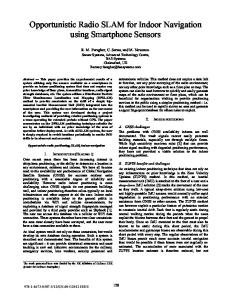
The overall architecture for this project (shown in Figure 1) is centered on a host computer running the Orca software framework and an Arduino microcontroller (MCU) system that controls the motion of the robot. Sensors serve as inputs to the system, collecting data to be processed and used to make driving decisions. A planned route and environmental map, specified in a Route Network Definition File (RNDF) and a Mission Definition File (MDF), are also inputs that prescribe a path for the robot to traverse. The servos and motors used to drive and steer the robot are outputs to the system, powered and controlled by the MCU.
Figure 1: High Level System Diagram The host computer and the Arduino MCU run several software interfaces that support the 9
various features of the autonomous robot. The components and interfaces provided in the Orca C++ repository perform a significant portion of the tasks required to run the system. There is a designated component and interface for each type of sensor that handles data collection and distribution. A path-planning module plans a route based on the provided definition files. A robot model component uses a control loop to determine how the robot should move based on its surroundings and the planned route. Local navigation and localization components map the environment around the robot, allowing the system to detect obstacles using sensor data. All this information is processed and communicated over a serial interface to the Arduino board to control the robot accordingly. The MCU, on the other hand, is responsible for controlling the robot’s servos and motors. The information supplied by the host computer is used to make driving decisions. Several IR sensors were installed on the robot to make emergency decisions if the robot somehow gets too close to an obstacle. The data from the IR sensors is only used by the MCU and not sent to the host computer. The MCU also collects data from an encoder that measures the rotation of the wheels. This feedback information is communicated to the robot model running on the host computer, allowing a closed loop control system to properly control the robot. This topology simplified the design since the more complex sensors were easier to handle with the host computer while the encoder and IR sensors were easily handled by the MCU. Two separate Arduino Mega 2560 boards were implemented to perform the microcontroller functions. One was responsible for receiving data from the computer and driving the robot while the other was used to collect and communicate encoder data. This approach simplified the serial traffic communication between the computer and the boards as it did not require time multiplexing the data that was communicated. Cameras, lasers, and GPS sensors were used to monitor the environment of the robot. Cameras collect visual data used to detect objects. Lasers scan a region around the vehicle and communicate information to the Orca components to generate a 2-dimensional occupancy grid around the robot. The GPS sensors track its geographical coordinates, permitting the system to determine its exact location. These sensors collected the necessary information to accurately and e↵ectively control the robot as it traversed a defined path. This project attempted to incorporate the sensors on Nokia’s N9 smartphones in the autonomous navigation system. Although these devices contain camera and GPS sensors, standalone webcams and GPS sensors were also incorporated in this project. These dedicated sensors provided accurate data and had drivers and libraries supplied by the manufacturers that could be integrated into the Orca platform with relative ease. Integrating the
10
sensors of smartphones would be more challenging as it would require the connecting the phone to the host computer using a mobile application.
3.2
Hardware Design & Implementation
The hardware of the system consisted of the robot, the host computer, the Arduino boards, and the sensors. Before this project was started, parts of the robot were already assembled. An Arduino board, servos, motors, IR sensors, and batteries were installed and connected. The motors, servos, and IR sensors were connected to the Arduino board instead of the host computer because those devices had wire connection interfaces, which could be easily read or driven using the pins from a microcontroller board. The motors and servos were driven by pulse-width modulated (PWM) signals from the Arduino board. A PWM signal is one which is high for a specific time interval during a clock period and low for the rest, resulting in an average voltage that is dependent on the width of the pulse. Therefore, motor rotation speed depends on the pulse width of the signal, thus a↵ecting the robot’s movement speed. An encoder was needed to collect information about the rotation of the wheels to be used as feedback for the closed loop controller. A device that met the size constraints of the wheels was acquired and installed on the robot. Since this device had a wire connection interface, it was connected to the Arduino board using the circuit shown in Figure 2. Pull-up resistors were needed since the encoder specifications required that the pins not be directly connected to the power supply.
Figure 2: Encoder Circuit Schematic The encoder has two signal pins (A and B) that are driven by square waves that are 90 degrees out of phase with each other, as shown in Figure 3. As the tip of the encoder rotates, the signal traverses along these waveforms concurrently. A transition event occurs 11
Figure 3: Encoder Pin Waveforms when one of the signals goes from high to low or low to high. There are thus four distinct transition events per cycle. The MCU tracked these two signals and incremented a counter every time a specific one of these transitions occurred while the encoder tip was rotated. Since the encoder specifications claim that there are 200 pulses in every revolution, the counter incremented by 200 when the encoder was rotated once completely. The encoder counter was sampled every 100 ms, the rotation speed was calculated using Eq. 1, and the data was transmitted to the host computer over a serial USB interface to be used in the robot model component. Counter V alue Circumf erence of the W heel ⇤ (1) 200 T ime A host computer with the Orca software was placed directly on the robot. The VectorNAV VN200 was used as a dedicated GPS sensor. A standalone webcam and a Hokuyo laser were also equipped on the robot. Each of these sensors was connected to the host using USB interfaces. Speed =
3.3
Software Design & Implementation
The Orca infrastructure supplies the robot with components and interfaces that collect sensor data, plan a route, and make driving decisions. The software was installed on a computer running Kubuntu 8.04, a version of the Linux operating system. This framework was implemented successfully on a previous autonomous vehicle project for the DARPA Grand Challenge and a customized version of the software was available. These modules were adapted to meet the design specifications for this project. The first major step was to get the sensors working on the host computer. The process required installing the device drivers and modifying the Orca component code to recognize the hardware. This step was completed for the VectorNAV VN200 GPS device and the 12
Hokuyo laser. The smartphones required designated applications to access the data from their sensors so getting these devices installed on the host computer proved to be a significant obstacle. This challenge was tackled by successfully testing the smartphone sensors on a host computer running the Windows operating system. However, software compatibility issues prevented the successful integration of the smartphone sensors on the Linux-based operating system. Planning and programming a route was another significant milestone. The simulation that was used in the previous project included a map and the goal was to replace it with a new one. A loop around Doe Library was decided as a viable test path so geographical coordinates were measured and a route was constructed. A new RNDF and MDF were written to specify the map and the route that would be used by the robot. The next step was to develop the robot model running on the computer that was used to control the robot. The previous project had controlled a full-sized automobile. Since this project used a scale model robot, many of the control parameters had to be adjusted. The model used in the previous project had controlled large actuators through several interface boards and received feedback information from a CAN bus. In contrast, this project controlled small servos and collected feedback data from encoders through Arduino boards. As a result, the model and controller software running on the computer were modified. On the Arduino side, a baseline version of the code was already programmed onto one of the boards so that the information provided by the IR sensors was used to drive and steer the robot. This program was modified to serially receive speed and steering angle data as PWM values from the Orca robot driver to control the motors and servos of the robot. As described earlier, a program was written to sample the encoder periodically and communicate the robot’s speed to the computer using the other board. A new Orca component was written to serially read the data from the Arduino board and pass the encoder data to the robot model component.
3.4
Testing Strategy
An incremental design and testing approach was followed for this project. Whenever a software component was modified, the subsystem was tested in isolation to troubleshoot issues before integrating into larger systems. After the VectorNAV GPS was successfully installed and the software was modified, the component was executed by itself to ensure that the sensor was collecting data correctly. Similarly, after the RNDF and MDF for a new route were designed, these files were fed into a simulation with baseline, functional versions of 13
the other components to simulate a vehicle with validated specifications traversing that test path designed for this project. A similar strategy was followed to test the encoder and the Arduino boards. At first, a simple program was developed to display the encoder rotation counter on a computer. After the functionality was validated, the rotation speed calculation was verified. The encoder was then mounted on the robot and a test was performed where the robot traversed in a straight line at a constant speed. The average speed was calculated by measuring the time needed to travel a certain distance and compare the result to the speed measured by the encoder. Once the encoder was validated, the speed of the robot was characterized by varying the pulse width of the signal driving the motors. This data was required by the robot controller component to drive the motors with the correct PWM values to achieve the desired speeds during run-time.
4
Discussion
Many challenges were encountered throughout this project, which provided valuable opportunities to learn and improve on the design approach. Although some features of the robot have not been fully integrated and tested, several important milestones have been met. This section will present the results, elaborate on unexpected results, compare the findings to those discussed in the literature, and discuss how this project fits in the broader field of autonomous vehicles.
4.1
Results
On the Arduino side, there were a number of key tasks. Serial communication with the host computer had to be established. The next step was to collect data from the rotary encoder. A serial connection between the board and the computer was established. The encoder data was successfully received and translated for use with the other Orca components. Several obstacles were overcome to make the encoder fully operational. Some of the wires connected to the encoder were stranded, or composed of many incredibly thin wires. This attribute made the wires difficult to connect to a breadboard. A solution to this issue was to connect the stranded wire to a single thick wire using alligator clips. Validating the accuracy of the speed measurements proved to be challenging. The encoder was initially spun by hand but it was difficult to gauge the accuracy of the collected data.
14
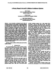
Figure 4: Encoder Results Figure 5: Robot Figure 4 shows the rotation speed measurements taken during encoder testing (in cm/s). As a result, a test was performed to measure the speed of the robot in motion. The time required for the robot to traverse a fixed distance in a straight line was measured and used to calculate its speed. In the meantime, the Arduino calculated the speed using the encoder. The results were compared to verify the measurement accuracy of the encoder. Figure 5 shows the robot during testing. During one of these trials, the robot accidentally grazed a wall, shearing part of the coupling that connected the encoder tip to a wheel. A custom encoder coupling was designed and built out of metal to improve the durability of the system. Furthermore, precautions were taken to more carefully monitor the system during testing after the incident. The encoder was then used to characterize the speed of the robot as a function of the pulse width of the signal that was used to drive the motors. Tests revealed that for a signal with a 20 ms period, the robot required a pulse width greater than 1.534 ms to start moving. The robot moved with a speed of approximately 1 m/s when a pulse width of 1.540 ms was applied. This speed was selected as the maximum allowable speed to continue testing the robot safely. Therefore, the robot controller communicated pulse widths in the range between 1.534 ms and 1.540 ms to the Arduino board driving the motors to operate the robot at speeds between 0 m/s and 1 m/s. Implementing the functions of the host computer also proved to be challenging. The robot model and controller were designed and implemented. To integrate the sensors into the system, drivers had to be installed and the corresponding Orca components for each of the sensors had to be configured. The standalone VectorNAV VN200 GPS module was installed successfully, the INSGPS Orca component was modified to read the data from the device, 15
and its functionality was verified in an outdoor setting. Integration of the laser has also been successfully implemented and verified. Attempts to integrate the smartphone sensors into the system were unsuccessful. The goal was to use a smartphone application called SmartCam to connect the cellphone camera to the host computer and operate the sensor like a standard webcam. This setup was successfully configured on a computer running the Windows operating system but not with the Kubuntu operating system. One possible solution would have been to install the Orca infrastructure on another operating system. However, this transition would have required a significant amount of overhead. As a result, di↵erent mobile operating systems were tested instead of PC operating systems. The Nokia N9 was preinstalled with the Meego operating system. The Android OS was installed and tested in an attempt to integrate the sensors of the N9. However, the e↵orts proved unsuccessful due to software compatibility issues, suggesting that upgrading the Orca system to a more recent Kubuntu installation might be the most beneficial step moving forward. To facilitate simulation and testing, a test path was defined for the robot to traverse. Geographical coordinates for a circular route in front of Doe Library were collected and included in the Mission Definition File (MDF) and Route Network Definition File (RNDF). The updated files were then incorporated into the simulation from the inherited project and the simulation ran successfully. Figure 6 captures the simulation during execution.
Figure 6: Simulation
16
4.2
Evaluation
Following a modular design methodology facilitated implementing and testing incremental design changes. For instance, it was easier to build and debug the encoder software for the Arduino board after the serial communication had been implemented and validated. Regardless, changing specifications and objectives hindered progress throughout the duration of the project. As an example, the project did not initially require using a laser scanner sensor. The initial plan had been to use the infrared sensors as replacements for a laser. However, it eventually became apparent that using a laser would dramatically help getting the simulation running more quickly. The time to integrate the sensors was further constrained as a result. Although it is difficult to anticipate new project needs, it is important to adapt quickly and manage time e↵ectively when issues arise. This project confirmed some of the findings in the literature. The design approach followed in this project was similar to some of those discussed in prior works. Robotic systems can be relatively complex, as they require a substantial amount of software and hardware integration. The Orca Robotics software framework significantly helped with design and implementation. The clear division of components and interfaces simplified reusing and adopting the framework for this project. Modeling the robot was a significant design challenge. Due to time constraints, a simple kinematic model was used instead of model predictive control (MPC). Although sensor integrity was difficult to guarantee in a variety of operating conditions, several di↵erent sensors were used in an attempt to improve system reliability. Looking at the challenges faced in integrating smartphones into this system, it is clear that improvements in smartphone technology may make them more viable in autonomous system applications in the future. Unfortunately, many smartphones today are still closed systems. Ideally, smartphones would run open-source operating systems that provide a flexible application programming interface (API) for developers. The Meego operating system running on the N9 is open-source but there are not many applications that take advantage of the sensors. There are substantially more applications on more popular open-source platforms like Android. These applications are updated more frequently, mitigating the chances of encountering compatibility issues. A possible next step for smartphones may be to run operating systems like Linux, providing open platforms for developers. Furthermore, smartphones can incorporate more high-end sensors like the GPS sensor in the VectorNAV VN200 module or the 41 Megapixel camera found in Nokia’s PureView devices. Although cost may be an initial concern, mass-production of these high-end sensors may reduce their cost in the long term. As smartphones continue to improve in computing 17
power and capability, they are eventually becoming hand-held computers. It may be possible to replace the host computer in this system with a smartphone running the Orca framework in the future. This project attempted to incorporate a variety of sensors, including those of smartphones, in an autonomous robotic system. The field of autonomous vehicles is definitely growing, with several projects currently in progress in academia and industry. This project aims to serve as a stepping-stone for other projects that might leverage the technology on larger vehicles that may ultimately transform transportation in the future.
5
Conclusion
There were many lessons learned throughout the duration of this project. Not getting stuck on every line of code proved to a major challenge in the beginning. However, building an overall understanding of what a section of code was executing became easier after looking through several software components in the Orca framework. As a result, it became easier to understand how a component needed to be modified to satisfy the project requirements. A related lesson was the importance of bookkeeping when adding more software and hardware components to the system. Carefully keeping track of dependencies and how data is communicated between components helped prevent errors. Another important lesson was realizing how complex robotics systems can be in terms of software and hardware. There are many challenges associated with collecting data from the sensors and using that information to control the robot. Furthermore, it is essential to assess and evaluate which types of sensors will provide the features that will satisfy the project specifications. Looking at this project from a cost standpoint, it is still unclear whether smartphone sensors will in fact reduce overall system cost. If the challenges faced in enabling these sensors on the robot are any indication, smartphones may pose even bigger issues for autonomous vehicles in the future. The ease with which this project can be scaled to larger vehicles is also uncertain. The fact that a significant amount of time was spent understanding the provided software and hardware before design and implementation was a major challenge. Since the project was inherited from a previous one, it was essential to comprehend how the components and interfaces worked together before they could be modified. As a result, the time limitation was further constrained. In contrast, a strength of the project and the team was the initia18
tive shown in taking responsibility of particular tasks. Work was divided based on interest and skill set. Future work would involve completing integration and testing the entire system. Since di↵erent mobile operating systems did not help in incorporating the smartphone sensors, the next step could be to upgrade the system running on the host computer. If the robot is thoroughly validated, a possible step would be scale the system to a larger vehicle such as a golf cart. The eventual goal would be to incorporate smartphone sensors in mass-produced fully autonomous vehicles. There will be many obstacles along the way but this technology has the potential to address the global issues of traffic congestion, fuel efficiency, and road safety.
19
References [1] R. Bishop. “Intelligent Vehicle Applications Worldwide”. Intelligent Systems and their Applications, IEEE, 15(1):78–81, 2000. [2] J. Borenstein and Y. Koren. “The Vector Field Histogram-Fast Obstacle Avoidance for Mobile Robots”. Transactions on Robotics and Automation, IEEE, 7(3):278–288, 1991. [3] A. de la Escalera, J. M. Armingol, and M. Mata. “Traffic Sign Recognition and Analysis for Intelligent Vehicles”. Image and Vision Computing, 21(3):247–258, 2003. [4] G.H. Elkaim, M. Lizarraga, and L. Pedersen. “Comparison of low-cost GPS/INS sensors for Autonomous Vehicle applications”. Position, Location and Navigation Symposium, 2008 IEEE/ION, pages 1133–1144, 2008. [5] D. Fox, W. Burgard, and S. Thrun. “The Dynamic Window Approach to Collision Avoidance”. Robotics & Automation Magazine, IEEE, 4(1):23–33, 1997. [6] H. Fritz. “Neural Speed Control for Autonomous Road Vehicles”. Control Engineering Practice, 4(4):507–512, 1996. [7] J. Funke, P. Theodosis, R. Hindiyeh, G. Stanek, K. Kritatakirana, C. Gerdes, D. Langer, M. Hernandez, B. Muller-Bessler, and B. Huhnke. Up to the limits: Autonomous audi tts. Intelligent Vehicles Symposium (IV), 2012 IEEE, pages 541–547, 2012. [8] A. Gray, Y. Gao, T. Lin, J. K. Hedrick, H. E. Tseng, and F. Borrelli. “Predictive Control for Agile Semi-Autonomous Ground Vehicles using Motion Primitives”. American Control Conference (ACC), pages 4239–4244, 2012. [9] E. Guizzo and T. Deyle. Robotics trends for 2012. IEEE ROBOTICS & AUTOMATION MAGAZINE, 2012. [10] J. K. Hedrick, M. Tomizuka, and P. Varaiya. “Control Issues in Automated Highway Systems”. Control Systems, IEEE, 14(6):21–32, 2012. [11] R. Holeywell. “States Look to Regulate Autonomous Autos”. http://www.governing. com/blogs/view/state-look-to-regulate-autonomous-autos.html. Accessed on April 14, 2013. [12] Barrie Kirk and P Eng. “Connected vehicles: an executive overview of the status and trends”. Globis Consulting, November, 21, 2011.
20
[13] T. B. Lee. “High Sensor Costs Won’t Stand in the Way of the SelfDriving Future”. http://www.forbes.com/sites/timothylee/2013/01/11/ high-sensor-costs-wont-stand-in-the-way-of-the-self-driving-future/. Accessed on April 14, 2013. [14] A. Makarenko, A. Brooks, and B. Upcroft. “An Autonomous Vehicle using Ice and Orca”. Connection: ZeroC’s Newsletter for the Ice Community, (22):2–6, 2007. [15] G. Marsden, M. McDonald, and M. Brackstone. “Towards an Understanding of Adaptive Cruise Control”. Transportation Research Part C: Emerging Technologies, 9(1):33–51, 2001. [16] U.S. Department of Transportation National Highway Trafc Safety Administration. “Traffic Safety Facts 2009 - Highlights of 2009 Motor Vehicle Crashes”, 2010. [17] A. C. Santos, L. Tarrataca, and J. M. P. Cardoso. “An Analysis of Navigation Algorithms for Smartphones Using J2ME”. Mobile Wireless Middleware, Operating Systems, and Applications, 7:266–279, 2009. [18] Y. Sekimoto, Y. Matsubayashi, H. Yamada, R. Imai, T. Usui, and H. Kanasugi. Lightweight lane positioning of vehicles using a smartphone gps by monitoring the distance from the center line. 15th International IEEE Conference on Intelligent Transportation Systems (ITSC), 2012, pages 1561–1565, 2012. [19] Girma S Tewolde. “Sensor and network technology for intelligent transportation systems”. International Conference on Electro/Information Technology (EIT), IEEE, pages 1–7, 2012. [20] O. Thomas. “Google’s Self-Driving Cars May Cost More Than A Ferrari”. http://www. businessinsider.com/google-self-driving-car-sensor-cost-2012-9. Accessed on April 14, 2013. [21] D Work and A Bayen. “Impacts of the mobile internet on transportation cyberphysical systems: traffic monitoring using smartphones”. National Workshop for Research on High-Confidence Transportation Cyber-Physical Systems: Automotive, Aviation, & Rail, pages 18–20, 2008. [22] S. Zaman, W. Slany, and G. Steinbauer. “ROS-Based Mapping, Localization and Autonomous Navigation using a Pioneer 3-DX Robot and their Relevant Issues”. Saudi International Electronics, Communications and Photonics Conference, pages 1–5, 2011.
21