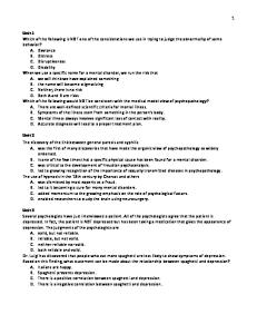
AHV AHH Horizontal Unit
Upflow Unit
BLOWER - COIL- FILTER UNITS 7.5-20 tons
AHV/AHH SERIES
Table of Contents . . . . . . . . . . . . . . . . . . . . . . . . . . . . . . . . . . . .Page Features & Accessories . . . . . . . . . . . . . . . . . . . 2-3 Drive Kit Selection . . . . . . . . . . . . . . . . . . . . . . . . 3 Installation Clearances . . . . . . . . . . . . . . . . . . . . . 3 Specifications . . . . . . . . . . . . . . . . . . . . . . . . . . . . 4 Blower Data . . . . . . . . . . . . . . . . . . . . . . . . . . . . 5-7 Hot Water Coil Pressure Drop . . . . . . . . . . . . . . . 7
. . . . . . . . . . . . . . . . . . . . . . . . . . . . . . . . . . . .Page Optional Electric Heat Data . . . . . . . . . . . . . . . . . 8 Guide Specifications . . . . . . . . . . . . . . . . . . . . . . . 9 Dimensions – AHV90 & AHV120 . . . . . . . . . . . . 10 Dimensions – AHH90 & AHH120 . . . . . . . . . . . . 11 Dimensions – Optional Accessories . . . . . . . 12-15 Hot Water Heating Capacity Curves . . . . . . . 16-17
Typical Applications
AHV/AHH / Page 1
FEATURES Application — AHV and AHH model blower-coil filter units provide installation versatility and maximum efficiency in cooling performance, air handling and filtering in cooling or heat pump applications. Units are available in two model styles, AHV series with up-flo supply air discharge or AHH series with horizontal supply air discharge. The units are equipped with dual circuit evaporator coils, this makes them suitable for application with LSAC remote condensing units or LSAP heat pump outdoor units. Each indoor coil circuit has a separate expansion valve and distribution system for two stage capacity control during cooling cycles. Blower coil units are shipped factory assembled ready to install. Blower drives are shipped separately and must be ordered extra. See condensing unit bulletins (section Spilt System Condensing Units) or heat pump outdoor units (section Split System — Heat Pump Units) for heatingcooling efficiencies and capacities. Completely Tested — Blower coil units are thoroughly tested with matching outdoor units according to ARI Standard test conditions. Blower performance data is from actual unit tests conducted in air test chamber. Units and components within are bonded for grounding to meet safety standards for servicing required by U.L., N.E.C. and C.E.C. Cabinet — Cabinet is constructed of heavy gauge galvanized steel. A five station metal wash preparation assures a perfect bonding surface for the finish coat of baked-on enamel. Cabinet is completely lined with thick fiberglass insulation resulting in quiet and efficient operation due to the excellent sound deadening and insulating qualities of fiberglass. Large removable panels are provided for complete service access. Electrical inlets are conveniently located in the cabinet. Dual Circuit Copper Tube Coil — Extra large surface area of coil provides maximum cooling efficiency, excellent heat transfer and low air resistance. Coil is face split with separate circuits, each circuit has its separate expansion valve. Precise circuiting gives uniform refrigerant distribution. Fabricated coil is constructed of precisely spaced ripple-edged aluminum fins fitted to durable seamless rifled copper tubes. Rifled tubing provides superior refrigerant flow resulting in maximum heat transfer. Fins are strengthened to resist bending and are equipped with collars that grip tubing for maximum contact area. Flared tubing connections and silver soldering provide tight, leakproof joints. Long life copper tubing is corrosion-resistant and easy to field service. Coil is thoroughly factory tested under high pressure to insure leakproof construction. Drain Pan — Deep, corrosion resistant drain pan is constructed of heavy gauge galvanized steel. Equipped with twin drain connections on both sides of cabinet as added protection from overflow. Belt Drive Blowers — AHV/AHH90 models are equipped with a single blower, AHV/AHH120, -180 & 240 models have dual blowers. Centrifugal belt driven blowers deliver large air volumes quietly and with low power consumption. Blower wheels are heavy duty, with forward curved blades and double inlet. Wheels are statically and dynamically balanced to eliminate vibration and designed to give maximum air delivery. Bearings are heavy duty, self aligning, permanently sealed and lubricated. All moving parts (blower wheels, drives and motor) are mounted on a rugged frame, resiliently mounted and isolated from the rest of the cabinet. Motor mounting frame allows simple belt adjustment and motor mounting. Adjustable motor pulley provides variable speed adjustments. A choice of motor outputs and drives are available and must be ordered extra. See drive kit table. AHV/AHH / Page 2 "
Expansion Valve — Factory installed and piped. Dual circuited coils have two expansion valves, one for each coil section. Valves are sized for best performance. Piping And Drain Connections — Refrigerant line inlets and drain connections are provided on both sides of the cabinet. Refrigerant lines require sweat connections and are made internal to the cabinet. Dual galvanized pipe drain outlets extend outside the cabinet for ease of connection. Air Filters — 1 inch (25 mm) thick throwaway fiberglass media filters are furnished as standard. Filter rack is adjustable to accommodate up to two inch (51 mm) thick throwaway or cleanable optional filters. Filter rack design permits quick and easy removal of filters for servicing.
OPTIONAL ACCESSORIES (Must Be Ordered Extra) Economizer Damper Section (Optional) — Factory assembled and wired economizer dampers and controls are available for field installation. Heavy gauge steel cabinet has a baked-on enamel finish and is completely insulated with thick matte faced fiberglass insulation. Large removable panels on both sides of cabinet provide complete service access. Mounting flanges provide ease of connection to unit. Flanges on outdoor air opening and return air opening permit easy duct connection. Economizer has mechanically linked outdoor air and recirculated air dampers. Formed dampers rotate smoothly in nylon bearings. Outdoor air dampers are reinforced and gasketed for tight seal and quiet operation. Damper linkage and shafts are plated. The positioning of the dampers is accomplished by a 24 volt fully modulating electronic spring return damper motor with adjustable minimum position potentiometer and controlled by the room thermostat, adjustable mixed air sensor and adjustable enthalpy control. The enthalpy control allows 0 to 100% outdoor air to be used for ”free cooling” when outdoor temperature and humidity are acceptable. Differential Enthalpy Control (Optional) — A solid-state return air enthalpy sensor is available to be used with the outdoor air enthalpy control to determine which air has the lowest enthalpy. The air with the lowest enthalpy will be selected. Return air enthalpy sensor field installs in the economizer damper section and must be ordered extra. Electric Heat (Optional) — Furnished in a separate add-on matching cabinet. Bolts, nuts and washers are furnished to secure cabinets together. Holes are pre-punched. Cabinet is constructed of heavy gauge galvanized steel with a baked-on enamel finish. Completely insulated with thick fiberglass insulation. Removable panel permits service access. Electrical inlet provides wiring entry. Factory installed electric heaters are available in several sizes, see electric heat data table. Helix wound nichrome heating elements are exposed directly in the air stream resulting in instant heat transfer, lower coil temperatures and long service life. Elements are accurately located and insulated from the heavy gauge steel support frame by high quality insulators. Time delays bring the elements on and off the line in sequence and equal increments in response to demand with a time delay between each element. Elements are equipped with individual limit controls providing positive protection in case of excessive overheating. Heaters may be two stage controlled with each stage being energized only when required. Heaters must be ordered extra. Sub-fusing, contactors, control relays, 24 volt transformer, terminal block and blower motor contactor are furnished as standard equipment.
Optional Accessories (Must Be Ordered Extra) Hot Water Heat (Optional) — Furnished in a separate add-on matching cabinet. Bolts, nuts and washers are furnished to secure cabinets together. Holes are pre-punched. Cabinet is constructed of heavy gauge galvanized steel with a baked-on enamel paint finish. Completely insulated with thick matte faced fiberglass insulation. Removable panel permits service access. Piping inlets are furnished in both sides of cabinet. Factory installed, designed and built coil has large face area, excellent heat transfer and low air resistance. Constructed of precisely spaced ripple-edged aluminum fins fitted to durable copper tubes. Fins are equipped with collars that grip tubing for maximum contact area. Flared shoulder tubing connections and silver soldering provide tight, leakproof joints. Long life copper tubing is easy to field service. Coil is thoroughly factory tested under high pressure to insure leakproof construction. Must be ordered extra. Valves and pumps must be furnished by installer. Return Air Grille (Optional) — Anodized aluminum grille field installs in return air opening of blower-coil unit. Must be ordered extra. Supply Air Plenum & Grille (Optional) — Constructed of heavy gauge galvanized steel with a baked-on enamel paint finish. Completely lined with thick matte faced fiberglass insulation. Equipped with anodized aluminum grille with double deflection and four-way directional control in vertical and horizontal planes for precise control of discharge air. Bolts, nuts and washers are furnished to secure plenum to cabinet. Must be ordered extra.
Spacer Cabinets (Optional) — Matching empty spacer cabinets give additional height required for plenum and grille in up-flow store cooler applications and provides spacing between unit and plenum and grille in horizontal installations not using an electric heat or hot water heat cabinet. Constructed of heavy gauge galvanized steel with a baked-on enamel paint finish. Completely lined with thick matte faced fiberglass insulation. Must be ordered extra. Suspension Kits (Optional For AHH90,-120 only) — Provides support of units in suspended horizontal applications. Kit consists of 2 angle iron channels with holes at each end. Kits are not available for the AHH180 & AHH240 models and must be field provided. Heat Pump Check Valve Kit (Optional) — Field installed kit contains check valves with connecting tubing, sweat connections. Kit must be ordered extra. See Specifications Table. Outdoor Thermostat (Optional) — An outdoor thermostat can be used to lock out some of the heating elements on units where two stage control is applicable. Outdoor thermostat maintains the heating load on the low power input as long as possible before allowing the full power load to come on the line. Thermostat and mounting box must be ordered extra. Blower Contactor Kit (Optional) — Contactor kit SSA10 is not furnished with the unit and must be ordered extra. Kit is not required with electric heaters. Kit requires a separate 20VA (minimum rating) transformer (not furnished).
DRIVE KIT SELECTION Using Total Air Volume and System External Static Pressure needed for unit requirements, determine from blower performance table blower speed and blower motor output required. Unit Size
Drive Kit Model Number N mber
–90 –120
–90, –120 –180, –240
Nominal Motor Output
�Max. Usable Motor Output
Voltage g and Phase
�Minimum Circuit Ampacity
RPM Range g
hp
W
hp
W
SSA51
1.5
1119
1.7
1268
200/230/460v — 60hz — 3ph
7.5/6.5/3.3
SSA41
2
1492
2.3
1716
200/230/460v — 60hz — 3ph
SSA42
3
2238
3.4
2536
SSA43
5
3730
5.7
4252
Shipping Weight lbs.
kg
600 — 820
39
18
9.9/8.5/4.3
730 — 950 (90/120 models) 520 — 660 (180/240 models)
45
20
200/230/460v — 60hz — 3ph
13.9/12.0/6.0
600 — 750
51
23
200/230/460v — 60hz — 3ph
21.9/19.0/9.5
690 — 830
70
32
–180, 180 –240 240 �Maximum useable output of motors furnished In Canada, nominal motor output is also maximum usable motor output. If motors of comparable output are used, be sure to keep within the service factor limitations outlined on the motor nameplate. �At rated voltages shown.
INSTALLATION CLEARANCES — inches (mm) Model Number
AHV90 AHH90
AHV120 AHH120
AHV180 AHH180
AHV240 AHH240
Cabinet
0 inch (0 mm)
0 inch (0 mm)
0 inch (0 mm)
0 inch (0 mm)
Plenum
1 inch (25 mm)
1 inch (25 mm)
1 inch (25 mm)
1 inch (25 mm)
Duct
*1 inch (*25 mm)
**1 inch (**25 mm)
*1 inch (*25 mm)
*1 inch (*25 mm)
*Within 3 feet (1 m) of the unit. **Within 4 feet (1.2 m) of the unit.
AHV/AHH / Page 3 "
SPECIFICATIONS Model Number Nominal Cooling Capacity — Tons (kW) Blower wheel nominal diameter x width — in. (mm)
AHV90 AHH90
AHV120 AHH120
AHV180 AHH180
AHV240 AHH240
7-1/2 (26)
10 (35)
15 (53)
20 (70)
(2) 15 x 11 (381 x 279)
(2) 15 x 15 (381 x 381)
(1) 15 x 15 (381 x 381) (2)15 x 9 (381 x 229)
Blower motor output and blower drives
See Drive Kit Table (shipped separately) in.
*Number and size of air filters mm Condensate drain connection — female pipe thread
(2) 16 x 25 x 1 (1) 20 x 25 x 1
(4) 16 x 25 x 1
(6) 16 x 20 x 1 (2) 16 x 25 x 1
(6) 20 x 20 x 1 (2) 20 x 25 x 1
(2) 406 x 635 x 25 (1) 508 x 635 x 25
(4) 406 x 635 x 25
(6) 406 x 508 x 25 (2) 406 x 635 x 25
(6) 508 x 508 x 25 (2) 508 x 635 x 25
in.
(2) 1-1/4
mm
(2) 31.8
Refrigerant
HCFC-22 Net face area — ft.2 (m2) Coil split — 1st stage/2nd stage (%)
7.98 (0.74)
10.07 (0.94)
60/40
61.9/38.1
Number of rows Evaporator E t Coil
17.38 (1.61)
23.16 (2.15)
53.8/46.2
52.9/47.1
4
Tube outside diameter — in. (mm)
3/8 (9.5)
Fins per inch (fins per m)
14 (551)
Suction line connection — outside diameter (sweat)
in.
Liquid q line connection — outside diameter (sweat)
in.
**Shipping g weight g — lbs. (kg) g ({2 packages)
1/2 (12.7) 13 (512)
1-3/8
mm
34.9
34.9 (2) 3/8
mm
(2) 1-1/8
(2) 1-3/8
(2) 28.5
(2) 34.9
(2) 1/2
(4) 3/8
(2) 9.5
(2) 9.5
(2) 12.7
(4) 9.5
Up-flow
350 (159)
418 (190)
720 (327)
815 (370)
Horizontal
312 (142)
379 (172)
760 (345)
860 (390)
b Optional Accessories (Must Be Ordered Extra) b Electric Heat Model Number Model Number Shipping weight — lbs. (kg)
ES90
ES120
ES240
SSA33
SSA34
SSA35
95 (43)
104 (47)
185,000 (54.2)
257,000 (75.3)
6.4 (0.59)
8.5 (0.79)
15.6 (1.45)
Tube outside diameter — in. (mm) number of rows
1/2 (12.7) 2
1/2 (12.7) 2
1/2 (12.7) 2
Fins per inch (fins per m)
12 (472)
12 (472)
12 (472)
1-3/8 (35) sweat
1-3/8 (35) sweat
1-5/8 (41) sweat
1-3/8 (35) sweat
1-3/8 (35) sweat
1-5/8 (41) sweat
Up-flow
SSA16 124 lbs. (56 kg)
SSA17 148 lbs. (67 kg)
SSA18 242 lbs. (110 kg)
Horizontal
SSA19 41 lbs. (19 kg)
SSA20 50 lbs. (23 kg)
SSA21 86 lbs. (39 kg)
Return Air Grille (shipping weight)
SSA25 29 lbs. (13 kg)
SSA26 37 lbs. (17 kg)
Empty Spacer Cabinet (shipping weight)
SSA22 55 lbs. (25 kg)
SSA23 60 lbs. (27 kg)
Economizer Dampers (shipping weight)
SSA29 145 lbs. (66 kg)
SSA30 185 lbs. (84 kg)
{{Heating capacity — Btuh (kW) Hot Water Coil
Net face area —
ft.2
(m2)
Inlet Water line connections Outside diameter — in. (mm) Outlet Supply pp y Air Plenum and Grille (shipping weight)
Differential Enthalpy Control Horizontal Suspension Kit (shipping weight) Heat Pump Check Valve Kit
160 (73) 405,000 (118.7)
SSA27 65 lbs. (29 kg)
462,000 (135.4)
SSA28 82 lbs. (37 kg)
SSA24 82 lbs. (37 kg) SSA31 395 lbs. (179 kg)
SSA32 542 lbs. (264 kg)
SSA11 SSA13 21 lbs. (10 kg)
SSA14 26 lbs. (11 kg) SSA6
Not Available SSA7
SSA9
*Standard filters are 1 inch (25 mm) thick. 2 inch (51 mm) filters may also be used. **Weight does not include motor and drives. {Packages consist of: blower coil unit and drive kit with motor and drives. {{Rated at 180_F (82_C) supply water temperature, 70_F (21_C) entering air temperature, 20_F (11_C) water temperature drop and 450 cfm air volume per ton (60 L/s air volume per kW) of cooling capacity. See Hot Water Capacity Curves for heating capacities at different conditions.
AHV/AHH / Page 4 "
BLOWER DATA AHV90 AND AHH90 BLOWER PERFORMANCE Air Volume cfm (L/s)
STATIC PRESSURE EXTERNAL TO UNIT — Inches Water Gauge (Pa) 0.2 (50)
0.3 (75)
0.4 (100)
0.5 (125)
0.6 (150)
0.7 (175)
0.8 (200)
0.9 (225)
1.0 (250)
1.25 (310)
1.5 (375)
RPM hp RPM hp RPM hp RPM hp RPM hp RPM hp RPM hp RPM hp RPM hp RPM hp RPM hp (W) (W) (W) (W) (W) (W) (W) (W) (W) (W) (W)
2000 (945)
----
----
2500 (1180)
----
----
---560
550
0.35 0.50 0.55 0.60 0.70 0.75 1.05 1.30 590 630 650 690 720 790 850 (261) (373) (410) (448) (522) (560) (783) (970)
0.30 0.55 0.65 0.75 0.80 .90 1.00 1.30 1.40 600 630 670 700 730 760 830 880 (224) (410) (485) (560) (597) (671) (746) (970) (1044)
3000 (1415)
560
0.60 0.65 0.75 0.85 0.95 1.00 1.15 1.25 1.30 1.55 1.80 590 625 650 690 720 750 775 800 860 925 (448) (485) (560) (634) (709) (746) (858) (933) (970) (1156) (1343)
3500 (1650)
620
0.95 1.05 1.05 1.15 1.30 1.35 1.50 1.60 1.65 1.95 2.20 650 685 715 740 770 800 825 840 910 970 (709) (783) (783) (858) (970) (1007) (1119) (1194) (1231) (1455) (1641)
4000 (1890)
1.40 1.50 1.60 1.65 1.75 1.85 1.95 2.05 2.15 700 725 750 775 800 825 850 875 900 (1044) (1119) (1194) (1231) (1306) (1380) (1455) (1529) (1604)
----
----
1.25 (310)
1.5 (375)
NOTE — All data is measured external to the unit with air filters in place.
AHV120 AND AHH120 BLOWER PERFORMANCE Air Volume cfm (L/s) 3000 (1415)
STATIC PRESSURE EXTERNAL TO UNIT — Inches Water Gauge (Pa) 0.2 (50)
0.3 (75)
0.4 (100)
0.5 (125)
0.6 (150)
0.7 (175)
0.8 (200)
.9 (225)
1.0 (250)
RPM hp RPM hp RPM hp RPM hp RPM hp RPM hp RPM hp RPM hp RPM hp RPM hp RPM hp (W) (W) (W) (W) (W) (W) (W) (W) (W) (W) (W) ----
550
0.50 0.60 0.70 0.80 .90 1.05 1.20 1.30 1.55 1.85 575 610 650 680 725 750 790 860 925 (373) (448) (522) (597) (671) (783) (895) (970) (1156) (1380)
3500 (1650)
550
0.60 0.70 0.80 .95 1.05 1.15 1.25 1.40 1.55 1.95 2.10 575 620 650 680 725 750 790 820 900 950 (448) (522) (597) (709) (793) (858) (933) (1044) (1156) (1455) (1567)
4000 (1890)
595
0.85 0.95 1.10 1.20 1.30 1.40 1.55 1.70 1.90 2.15 625 665 700 725 750 790 820 850 920 (634) (709) (821) (895) (970) (1044) (1156) (1268) (1417) (1604)
----
4500 (2125)
650
1.15 1.30 1.40 1.55 1.70 1.80 1.95 2.10 2.25 680 715 740 755 810 840 870 890 (858) (970) (1044) (1156) (1268) (1343) (1455) (1567) (1679)
----
----
5000 (2360)
1.55 1.70 1.80 1.95 2.15 2.30 710 730 760 800 825 850 (1156) (1268) (1343) (1455) (1604) (1716)
----
----
----
----
----
5500 (2595)
2.00 2.10 2.30 750 775 815 (1492) (1567) (1716)
----
----
----
----
----
1.0 (250)
1.25 (310)
----
----
----
NOTE — All data is measured external to the unit with air filters in place.
AHV180 AND AHH180 BLOWER PERFORMANCE Air Volume cfm (L/s)
STATIC PRESSURE EXTERNAL TO UNIT — Inches Water Gauge (Pa) 0.1 (25)
0.2 (50)
0.3 (75)
0.4 (100)
0.5 (125)
0.6 (150)
0.7 (175)
0.8 (200)
0.9 (225)
RPM hp RPM hp RPM hp RPM hp RPM hp RPM hp RPM hp RPM hp RPM hp RPM hp RPM hp (W) (W) (W) (W) (W) (W) (W) (W) (W) (W) (W)
5000 (2360)
----
5500 (2595)
----
---495
500
1.00 1.05 1.20 1.50 1.55 1.65 1.75 1.90 2.25 530 560 630 640 660 685 720 800 (746) (783) (895) (1119) (1156) (1231) (1306) (1417) (1679)
1.05 1.20 1.35 1.50 1.65 1.70 1.85 2.05 2.20 2.55 525 555 585 635 650 680 710 740 825 (783) (895) (1007) (1119) (1231) (1268) (1380) (1529) (1641) (1902)
1.20 1.30 1.45 1.60 1.75 1.90 2.10 2.20 2.35 2.50 2.90 520 550 580 610 640 675 705 730 760 840 (895) (970) (1082) (1194) (1306) (1417) (1567) (1641) (1753) (1865) (2163)
6000 (2830)
490
6500 (3065)
1.45 1.60 1.75 1.90 2.05 2.25 2.35 2.50 2.65 2.75 3.30 515 550 575 610 635 670 700 725 750 780 870 (1082) (1194) (1306) (1417) (1529) (1679) (1753) (1865) (1977) (2052) (2462)
7000 (3305)
1.75 1.90 2.05 2.25 2.35 2.55 2.65 2.85 3.00 3.20 550 575 605 635 665 690 720 745 775 810 (1306) (1417) (1529) (1679) (1753) (1902) (1977) (2126) (2238) (2387)
----
7500 (3540)
2.05 2.25 2.55 2.45 2.75 2.90 3.05 3.25 3.40 3.55 575 605 635 660 690 720 740 775 800 835 (1529) (1679) (1828) (1902) (2052) (2163) (2275) (2425) (2536) (2648)
----
8000 (3775)
2.40 2.60 2.80 2.95 3.15 3.30 3.50 3.65 3.85 4.10 605 635 660 690 720 740 775 800 835 870 (1790) (1940) (2089) (2201) (2350) (2462) (2611) (2723) (2872) (3059)
----
NOTE — All data is measured external to the unit with air filters in place.
AHV/AHH / Page 5 "
BLOWER DATA AHV240 AND AHH240 BLOWER PERFORMANCE Air Volume cfm (L/s) 6500 (3065) 7000 (3305) 7500 (3540) 8000 (3775) 8500 (4010) 9000 (4245) 9500 (4485) 10,000 (4720) 10,500 (4955)
STATIC PRESSURE EXTERNAL TO UNIT — Inches Water Gauge (Pa) 0.1 (25)
0.2 (50)
0.3 (75)
0.4 (100)
0.5 (125)
0.6 (150)
0.7 (175)
0.8 (200)
0.9 (225)
1.0 (250)
1.25 (310)
RPM hp RPM hp RPM hp RPM hp RPM hp RPM hp RPM hp RPM hp RPM hp RPM hp RPM hp (W) (W) (W) (W) (W) (W) (W) (W) (W) (W) (W) 1.35 515 (1007) 1.55 525 (1156) 1.70 530 (1268) 1.90 540 (1417) 2.15 555 (1604) 2.35 565 (1753) 2.65 585 (1977) 3.05 610 (2275) 3.35 625 (2499)
1.45 (1082) 1.70 545 (1268) 1.85 555 (1380) 2.15 565 (1604) 2.30 580 (1714) 2.60 595 (1940) 2.95 620 (2201) 3.30 635 (2462) 3.55 655 (2648) 535
1.70 (1268) 1.85 575 (1380) 2.05 585 (1529) 2.25 590 (1679) 2.55 610 (1902) 2.85 630 (2126) 3.15 640 (2350) 3.45 660 (2574) 3.80 685 (2835) 570
1.80 (1343) 2.00 600 (1492) 2.25 615 (1679) 2.45 625 (1828) 2.70 630 (2014) 3.05 655 (2275) 3.05 670 (2275) 3.30 690 (2462) 4.05 715 (3021) 585
1.90 (1417) 2.15 625 (1604) 2.30 630 (1716) 2.65 650 (1977) 2.90 665 (2163) 3.20 680 (2387) 3.55 700 (2648) 3.90 720 (2909) 4.30 745 (3208) 615
2.00 (1492) 2.30 650 (1716) 2.55 665 (1902) 2.80 675 (2089) 3.10 690 (2313) 3.40 710 (2536) 3.75 730 (2798) 4.10 750 (3059) 4.60 775 (3432) 635
2.25 (1679) 2.45 680 (1828) 2.65 685 (1977) 2.95 705 (2201) 3.20 720 (2387) 3.55 735 (2648) 3.90 755 (2909) 4.35 775 (3245) 4.75 800 (3544) 670
2.30 (1716) 2.55 705 (1902) 2.80 720 (2089) 3.05 730 (2275) 3.35 745 (2499) 3.75 760 (2798) 4.15 785 (3096) 4.55 805 (3394) 5.05 830 (3767) 690
2.45 (1828) 2.70 730 (2014) 2.90 740 (2163) 3.35 760 (2499) 3.60 775 (2686) 4.00 795 (2894) 4.40 815 (3282) 4.85 835 (3618) 5.40 860 (4028) 720
2.50 (1865) 2.80 755 (2089) 3.15 770 (2350) 3.40 785 (2536) 3.80 805 (2835) 4.20 820 (3133) 4.65 840 (3469) 5.15 860 (3842) 5.70 880 (4252) 740
NOTE — All data is measured external to the unit with air filters in place.
SUPPLY AIR PLENUM AND GRILLE AIR THROW DATA Blower Coil and Supply Plenum and Grille M d l Number Model N b
{AHV90 With { SSA16 or AHH90 With SSA19
{AHV120 With SSA17 or AHH120 With SSA20
{ {AHV180 With SSA18 or AHH180 With SSA21
{AHV2420 With { SSA18 or AHH240 With SSA21
me Air Vol Volume cfm
*Effective Throw — ft. (m) {10 ft. (3.0 m) Ceiling
L/s
Front of Unit
2000
945
40 (12.2)
31 (9.4)
2500
1180
46 (14.0)
36 (11.0)
3000
1415
53 (16.2)
41 (12.5)
3500
1650
56 (17.1)
45 (13.7)
4000
1890
63 (19.2)
50 (15.2)
3000
1415
50 (15.2)
35 (10.7)
3500
1650
55 (16.8)
40 (12.2)
4000
1890
61 (18.6)
44 (13.4)
4500
2125
67 (20.4)
50 (15.2)
5000
2360
71 (21.6)
56 (17.1)
5500
2595
74 (22.6)
61 (18.6)
5000
2360
30 (9.1)
19 (5.8)
5500
2595
31 (9.4)
19 (5.8)
6000
2830
35 (10.7)
22 (6.7)
6500
3070
36 (11.0)
22 (6.7)
7000
3305
36 (11.0)
22 (6.7)
7500
3540
39 (11.9)
24 (7.3)
8000
3775
41 (12.5)
26 (7.9)
6500
3070
36 (11.0)
22 (6.7)
7000
3305
36 (11.0)
22 (6.7)
7500
3540
39 (11.9)
24 (7.3)
8000
3775
41 (12.5)
26 (7.9)
8500
4010
43 (13.1)
27 (8.2)
9000
4250
46 (14.0)
29 (8.8)
9500
4485
49 (14.9)
30 (9.1)
10,000
4720
53 (16.2)
33 (10.1)
10,500
4955
55 (16.8)
34 (10.4)
45_ From Unit
*Effective throw is terminated at a point where conditioned air reaches a level of 3 feet (1 m) above the floor or where velocity has decreased to 50 feet per minute (0.25 m/s). {Ceiling height not applicable to AHV Up-Flow models.
AHV/AHH / Page 6 "
2.95 (2201) 3.25 820 (2425) 3.60 825 (2686) 3.95 840 (2947) 4.40 855 (3282) 4.70 870 (3506) 5.15 890 (3842) 805
-------
BLOWER DATA ACCESSORY AIR RESISTANCE — AHV90, AHH90, AHH120 AND AHV120
AHV90 AHH90
AHV120 AHH120
Total Resistance — inches water gauge (Pa)
Air Volume Vol me
Model M d l Number
Hot Water Coil
Economizer Dampers
cfm
L/s
SSA33
SSA34
SSA29
SSA30
2000
945
0.13 (32)
----
0.02 (5)
----
2500
1180
0.16 (40)
----
0.04 (10)
----
3000
1415
0.18 (45)
----
0.07 (17)
----
3500
1650
0.20 (50)
----
0.09 (22)
----
4000
1890
0.24 (60)
----
0.12 (30)
----
3000
1415
----
0.14 (35)
----
0.03 (70)
3500
1650
----
0.17 (42)
----
0.05 (12)
4000
1890
----
0.18 (45)
----
0.07 (17)
4500
2125
----
0.20 (50)
----
0.09 (22)
5000
2360
----
0.24 (60)
----
0.11 (27)
5500
2595
----
0.27 (67)
----
0.13 (32)
NOTE — Electric heat section, plenum and grilles have no appreciable air resistance.
ACCESSORY AIR RESISTANCE — AHV180, AHH180, AHH240 AND AHV240
AHV180 AHH180
AHV240 AHH240
Total Resistance — inches water gauge (Pa)
Air Volume Vol me
Model M d l Number
Hot Water Coil
Economizer Dampers
cfm
L/s
SSA35
SSA31
SSA32
5000
2360
0.08 (20)
0.04 (10)
----
5500
2595
0.10 (25)
0.05 (12)
----
6000
2830
0.11 (27)
0.06 (15)
----
6500
3070
0.13 (32)
0.07 (17)
----
7000
3305
0.15 (37)
0.08 (20)
----
7500
3540
0.17 (42)
0.09 (22)
----
8000
3775
0.18 (45)
0.10 (25)
----
6500
3070
0.13 (32)
----
0.04 (10)
7000
3305
0.15 (37)
----
0.05 (12)
7500
3540
0.17 (42)
----
0.06 (15)
8000
3775
0.18 (45)
----
0.07 (17)
8500
4010
0.21 (52)
----
0.08 (20)
9000
4250
0.23 (57)
----
0.08 (20)
9500
4485
0.25 (62)
----
0.09 (22)
10,000
4720
0.27 (67)
----
0.10 (25)
10,500
4955
0.30 (75)
----
0.11 (27)
NOTE — Electric heat section, plenum and grilles have no appreciable air resistance.
HOT WATER COIL PRESSURE DROP Flow Rate
Pressure Drop — feet of water (kPa)
gpm
L/s
SSA33
SSA34
SSA35
15
0.95
0.93 (3.0)
1.18 (3.5)
----
20
1.25
1.56 (4.5)
1.99 (6.0)
0.55 (1.5)
25
1.60
2.33 (7.0)
2.97 (9.0)
0.82 (2.5)
30
1.90
3.24 (9.5)
4.13 (12.5)
1.14 (3.5)
35
2.20
4.27 (12.5)
5.44 (16.0)
1.50 (4.5)
40
2.50
5.44 (16.0)
6.92 (20.5)
1.91 (5.5)
45
2.85
6.72 (20.0)
8.56 (25.5)
2.36 (7.0)
50
3.15
----
----
2.86 (8.5)
55
3.45
----
----
3.39 (10.0)
60
3.80
----
----
3.97 (12.0)
65
4.10
----
----
4.58 (13.5)
70
4.40
----
----
5.23 (15.5) AHV/AHH / Page 7 "
OPTIONAL ELECTRIC HEAT DATA ELECTRIC HEAT FOR AHV/AHH-90 and -120 Electric Heat Model No. and Shipping Weight
No. of Steps
Volts Input I
kW Input I
Btuh Output O
200
10.4
35,500
210
11.5
39,200
220
12.6
43,000
Minimum Circuit Ampacity 1-1/2 hp 2 hp (1119W) (1492W) 46 8 46.8
1 15ES90 (170 lbs.) (77 kg) 15ES120 (193 lbs.) (88 kg)
1
1
230
13.8
47,100
240
15.0
51,200
30ES90 (176 lbs.) (80 kg) 30ES120 (200 lbs.) (91 kg)
1
1
45ES90 (182 lbs.) (83 kg) 45ES120 (207 lbs.) (94 kg)
**2
**2
60ES120 (214 lbs.) (97 kg)
**2
**2
53.4
11.5 39,200
220
12.6 43,000
230
13.8 47,100
15ES240 (191 lbs.) (87 kg)
240
15.0 51,200
440
12.6 43,000
460
13.8 47,100
480
15.0 51,200
550
12.6 43,000
575
13.8 47,100
12.6
43,000
13.8
47,100
480
15.0
51,200
550
12.6
43,000
575
13.8
47,100
600
15.0
51,200
600
15.0 51,200
200
20.8
71,000
200
20.8 71,000
210
23.0 78,500
220
25.2 86,000
230
27.5 93,900
240
30.0 102,400
440
25.2 86,000
460
27.5 93,900
25.6
21.0
26.6
21.3
1
1
88 4 88.4
210
23.0
78,500
220
25.2
86,000
230
27.5
93,900
240
30.0
102,400
440
25.2
86,000
460
27.5
93,900
480
30.0
102,400
480
30.0 102,400
550
25.2
86,000
550
25.2 86,000
575
27.5
93,900
575
27.5 93,900
600
30.0
102,400
600
30.0 102,400
200
31.3
106,800
200
31.3 106,800
210
34.5 117,700
220
37.8 129,000
230
41.3 141,100
240
45.0 153,600
440
37.8 129,000
460
41.3 141,000
480
45.0 153,600
550
37.8 129,000
575
41.3 141,000
600
45.0 153,600
200
41.7 142,300
210
46.0 157,000
220
50.4 172,000
230
55.1 188,100
240
60.0 204,800
440
50.4 172,000
460
55.1 188,100
**2 96.5
48.3
39.0
200
34.5
117,700
220
37.8
129,000
230
41.3
141,000
240
45.0
153,600
440
37.8
129,000
460
41.3
141,000
480
45.0
153,600
550
37.8
129,000
575
41.3
141,000
600
45.0
153,600
200
41.7
143,400
210
46.0
157,000
220
50.4
172,000
230
55.1
188,100
240
60.0
204,800
98.5
49.3
30ES240 (195 lbs.) (88 kg)
39.3
1
1
128 0 128.0 **3
141.6
70.8
57.0
143.6
71.8
45ES240 (205 lbs) (93 kg)
57.3
**2
**2
167 5 167.5 **4
186.8
188.8 60ES240 (209 lbs.) (95 kg)
440
50.4
172,000
460
55.1
188,100
480
60.0
204,800
480
60.0 204,800
550
50.4
172,000
550
50.4 172,000
575
55.1
188,100
575
55.1 188,100
600
60.0
204,800
600
60.0 204,800
93.4
75.0
94.4
75.3
*Refer to National or Canadian Electrical Code manual to determine wire, fuse and disconnect size requirements. Use wires suitable for at least 167°F (75_C). **May be used with two stage control.
AHV/AHH / Page 8 "
10.4 35,500
210
460
165 4 165.4 **4
200 48 9 48.9
440
125 9 125.9 **3
Minimum Electric Heat Circuit Ampacity No. Volts kW Btuh Model No. of Input Output I IInput O and 2 hp 3 hp 5 hp Shipping Weight Steps (1149W) (2238W) (3730W)
1 51.4
86 3 86.3 **2
ELECTRIC HEAT FOR AHV/AHH180 and -240
**2
**2
48 8 48.8
52 7 52.7
60 3 60.3
53.6
57.1
64.1
26.8
28.6
32.1
21.4
22.9
25.7
88 3 88.3
92 2 92.2
99 8 99.8
98.8
102.3
109.3
49.4
51.1
54.6
39.5
41.0
43.7
127 8 127.8
131 6 131.6
139 3 139.3
143.9
147.4
154.4
71.9
73.7
77.2
57.5
59.0
61.8
167 2 167.2
171 1 171.1
178 7 178.7
189.0
192.5
199.5
94.5
96.3
99.8
75.5
77.1
79.8
*Refer to National or Canadian Electrical Code manual to determine wire, fuse and disconnect size requirements. Use wires suitable for at least 167°F (75_C). **May be used with two stage control.
GUIDE SPECIFICATIONS Prepared for the guidance of architects, consulting engineers and mechanical contractors. General — Furnish and install a blower-coil-filter unit. The unit shall be a standard product of a firm regularly engaged in the manufacture of heating-cooling equipment throughout the United States and Canada. The installed weight shall not be more than . . . . . . . lbs. (kg). Unit shall have a width of not more than . . . . . . . inches (mm), a depth of not more than . . . . . . . inches (mm) and an overall height of not more than . . . . . . . inches (mm). The equipment shall be shipped assembled ready for necessary field connections. Blower motor and pulley shall be shipped separate and field installed. AHV models shall be capable of up-flow air distribution. AHH models shall have horizontal air distribution. DX Cooling System — The total certified cooling capacity shall not be less than . . . . . . . . Btuh (kW) with an evaporator air volume of . . . . . . . cfm (m 3/s), an entering wet bulb temperature of . . . . . . . _F (_C) and . . . . . . _F (_C) coil refrigerant evaporating temperature. The coil shall be non-ferrous construction with aluminum fins machine fitted to copper tubes. The coil shall be dual circuit with each circuit having an expansion valve. Coil shall be factory pressure leak tested. Coil face area shall be not less than . . . . . . . sq. ft. (m 2). Control option shall include Latent Load Control. Heat Pump Heating System — The total certified heating capacity shall not be less than . . . . . . . Btuh (kW) with an indoor coil air volume of . . . . . . .. cfm (L/s), an entering dry bulb temperature of . . . . . . . _F (_C) and a condensing temperature of . . . . . . . _F (_C). Air Movers — Centrifugal conditioned air blowers shall have statically and dynamically balanced, forwardly curved, double inlet blower wheels, permanently lubricated bearings, adjustable belt drives and be capable of delivering . . . . . . . cfm (L/s) at an external static pressure of . . . . . . .inches water gauge (Pa), requiring not more than . . . . . . . bhp (W) and . . . . . . . rpm. AHV/ AHH90 models shall be equipped with a single blower. AHV/ AHH120, 180 and 240 models shall have dual blowers. Cabinet — The unit cabinet shall be constructed of galvanized steel with a baked-on enamel finish. Panels shall be insulated with not less than one inch (25mm) thick fiberglass insulation. Cabinet shall be equipped with large removable panels providing service access to interior. Inlets shall be provided for refrigerant line and power connection entry. Dual drain connections shall be accessible external to the cabinet. Air Filters — One inch (25 mm) thick throwaway filters furnished shall have not less than . . . . . . . sq. ft. (m 2) of area. Filter rack shall be capable of holding optional two inch (51 mm) thick throwaway or cleanable filters.
OPTIONAL ACCESSORIES (Must Be Ordered Extra) Additive Electric Heat — The certified total heating capacity output shall be . . . . . . . . Btuh with . . . . . . . . kw input at . . . . . . . . volts power supply. Optional electric heaters shall be available in a separate matching cabinet. Heating elements shall be nichrome bare wire exposed directly to the air stream. Time delays shall bring the elements on and off in sequence with a time delay between each element. Limit controls shall provide overload and short circuit protection. Cabinet shall be constructed of galvanized steel with a baked-on enamel paint finish and insulated with fiberglass insulation. Shall have removable access panel and electrical inlets. Additive Hot Water Heat — The certified total heating capacity output shall be . . . . . . . . Btuh (kW) with a heating coil air volume of . . . . . . . cfm (L/s), at a water entering temperature of . . . . . . . _F (_C) and a flow rate of . . . . . . . gpm (L/s) and an entering air temperature of . . . . . . . _F (_C). Optional hot water coil shall be available in a separate matching cabinet. Cabinet shall be constructed of galvanized steel with a baked-on enamel finish and insulated with fiberglass insulation. Shall have removable access panel and piping inlet openings. The coil shall be non-ferrous construction with aluminum fins mechanically bonded to copper tubes. Coil shall be factory pressure leak tested. Coil face area shall be not less than . . . . . . . sq. ft (m 2). Economizer Damper Section — Furnish and install complete with controls an optional air mixing damper assembly including outdoor air and recirculated air dampers. The assembly shall provide for the introduction of outside air for minimum ventilation and free cooling. The assembly shall be furnished in a fully insulated heavy gauge galvanized steel cabinet with baked-on enamel finish. The damper motor shall be 24 volt, fully modulating electronic spring return. Controls shall include adjustable mixed air sensor, adjustable minimum position potentiometer, and adjustable enthalpy control. Optional differential enthalpy control (return air sensor) shall be available. Supply Air Plenum and Grille — Optional plenum and grille shall be constructed of galvanized steel with baked-on enamel paint finish and insulated with fiberglass insulation. Shall be equipped with anodized aluminum discharge air grille with double deflection and four-way directional control in the vertical and horizontal planes. Spacer Cabinets — Optional empty cabinets shall match cabinet sections in size and provide necessary spacing between cabinet sections for varying applications. Shall be constructed of galvanized steel with baked-on enamel paint finish and insulated with fiberglass insulation. Return Air Grille — Optional anodized grille shall be available for field addition to blower-coil unit. Suspension Kit — Kit shall be available for AHH90 and AHH120 models in suspended horizontal applications. AHV/AHH / Page 9 "
DIMENSIONS — inches (mm) AHV90 AND AHV120 HORIZONTAL MODELS 64 (1626)
52 (1321) 1 (25)
7-3/4 (197)
9-1/2 (241)
12-7/8 (327)
SUPPLY AIR OPENINGS
12-7/8 (327)
1 (25)
16-3/8 (416)
18-5/8 (473)
12-1/4 (311)
27 (686)
27 (686)
ELECTRICAL INLET (Electric Heat)
SUPPLY END (AHV90)
ELECTRICAL INLET (Electric Heat)
SUPPLY END (AHV120)
16-3/8 (416)
SUPPLY AIR OPENING
27 (686) AIR FLOW
ELECTRICAL INLET (Either Side)
BLOWER
EXTERNAL STATIC PRESSURE TEST HOLE
2-1/16 (52)
LIQUID LINE INLETS (2) (Either Side)
2-1/16 (52)
47-7/8 (1216) — AHV90
AIR FILTERS
59-7/8 (1521) — AHV120 24-1/2 (622)
2-1/2 (64)
2 (51) 6 (152) 2 (51)
INDOOR COIL
57-1/2 (1461) — AHV120
8 (203)
SUCTION (VAPOR) LINE INLETS (Either Side)
2-1/2 (64)
45-1/2 (1156) — AHV90
3/4 (19)
49 (1245)
AIR FLOW
RETURN AIR OPENING
1-1/2 (38)
52-1/2 (1308)
12-7/8 (352)
4 (102) 12-1/4(311)
3/4 (19) INLET END
2-1/2 (64)
4 (102)
CONDENSATE DRAIN (Either Side)
DRIVE END VIEW
AHV180 AND AHV240 HORIZONTAL MODELS 1 (25) 9-3/8 (238)
17-3/8 (441)
19 (483)
16-5/8 (422)
19 (483)
ELECTRICAL INLET (Electric Heat)
SUPPLY AIR OPENINGS
A SUPPLY END
INDOOR COIL
85 (2159)
AIR FILTERS
1 (25) 10 (254)
42-1/8 (1070) AHV240 ONLY
44 (1118)
1-5/8 (41)
7/8 (22)
7/8 (22)
4 (102)
75-1/2 (1918)
A
C F
C
CONDENSATE DRAIN (Either Side)
3 (76)
C
in.
mm
E
10-5/8 (207)
10-1/2 (267)
SUCTION (VAPOR) LINE INLETS (Either Side)
1-7/8 (48)
DRIVE END VIEW
B mm
F
AIR FLOW
3/4 (19)
INLET VIEW
in.
D
B
4 (102)
No Model No.
BLOWERS
47 (1194)
81-3/4 (2076)
3/4 (19)
AIR FLOW
LIQUID LINE INLETS (Either Side)
33-1/8 (841) AHV180 ONLY
RETURN AIR OPENING
1-5/8 (41)
ELECTRICAL INLET
D
E
F
in.
mm
in.
mm
in.
mm
in.
mm
AHV180
35
889
18-3/8
467
2-1/2
57
12-1/2
318
22-5/8
575
1-1/4
32
AHV240
44
1118
22-3/4
578
2–5/8
67
14-1/4
362
22-1/2
572
4-7/8
124
AHV/AHH / Page 10 "
DIMENSIONS — inches (mm) AHH90 AND AHH120 HORIZONTAL MODELS 64 (1626)
16-3/8 (416)
12-7/8 (327)
2-1/4 (57)
ELECTRICAL INLET (Electric Heat)
52 (1321)
12-7/8 (327)
9-1/2 (241)
27 (686)
ELECTRICAL INLET (Electric Heat)
9-1/2 (241)
SUPPLY AIR OPENING
16-3/8 (416)
18-5/8 (473) 2-1/4 (57)
SUPPLY AIR OPENINGS
SUPPLY END (AHH90)
SUPPLY END (AHH120)
36 (914)
1-1/4 (32)
AIR FLOW
RETURN AIR OPENING
BLOWERS
INDOOR COIL
24-1/2 (622)
LIQUID LINE INLETS (2) (Either Side)
2-1/16 (52)
47-7/8 (1216) — AHH90 59-7/8 (1521) — AHH120
EXTERNAL STATIC PRESSURE TEST HOLE
13-1/4 (337)
ELECTRICAL INLET (Either Side)
2-1/16 (52)
27 (686)
12-1/4 (311)
2 (51)
SUCTION (VAPOR) LINE INLET (Either Side)
INLET END
AIR
6 (152)
FLOW
2 (51)
AIR FILTERS 1-1/4 (32)
6 (152)
CONDENSATE DRAIN (Either Side)
12-3/8 (314)
DRIVE END VIEW
AHH180 AND AHH240 HORIZONTAL MODELS 85 (2159)
A 19 (483)
16-5/8 (422)
1 (25)
ELECTRICAL INLET (Electric Heat)
19 (483)
17-3/8 (441)
9-3/8 (238)
SUPPLY AIR OPENINGS
44 (1118)
SUPPLY END
ELECTRICAL INLET (Either Side)
1-1/8 (29)
1-1/2 (38)
SUCTION (VAPOR) LINE INLETS (Either Side)
1-1/2 (38)
82 (2083)
G
LIQUID LINE INLETS (Either Side)
F
AIR FILTERS
E
AIR FLOW
RETURN AIR OPENING
C B
D
10-5/8 (207)
7/8 (22)
7/8 (22) 10-1/2 (267)
INLET END A Model No No.
AIR
E
C
FLOW
BLOWERS
CONDENSATE DRAIN (Either Side)
DRIVE END VIEW
B
C
D
E
F
G
in.
mm
in.
mm
in.
mm
in.
mm
in.
mm
in.
mm
in.
mm
AHH180
35
889
18-3/8
467
2-1/4
57
22-5/8
575
1-1/4
32
13-1/8
333
33
838
AHH240
44
1118
22-11/16
576
2-5/8
67
22-7/16
570
4-7/8
124
14-7/8
378
42
1067
AHV/AHH / Page 11 "
OPTIONAL ACCESSORY DIMENSIONS — inches (mm) ES90 AND ES120 ELECTRIC HEAT SECTION A
17-5/8 (448)
ELECTRIC INLETS
INLET AIR WIRING OUTLET OPENING (To Blower Motor)
24 (610) OUTDOOR AIR
27 (686)
AIR
19-1/2 (495)
D
A
7/8 (22)
19 (483)
OPENING
C
FLOW
B
1 (25)
1 (25) INLET VIEW
FRONT VIEW A
Model No. No
OUTLET VIEW
B
C
D
in.
mm
in.
mm
in.
mm
in.
mm
ES90
52
1321
29-7/8
759
14-9/16
370
21-1/16
535
ES120
64
1626
39-7/8
1013
18-1/8
470
37-15/16
948
ES240 ELECTRIC HEAT SECTION
20-1/2 (521)
85 (2159)
14-1/8 (359)
WIRING OUTLET (To Blower Motor) INLET AIR OPENING
1 (25)
14 (356)
85 (2159)
AIR
14-1/2 (368)
20-1/2 (521)
35 (889)
FLOW
20-1/4 (514)
OUTDOOR AIR
29-7/8 (759)
16-7/8 (429)
1 (25)
1 (25)
ELECTRIC INLETS
INLET VIEW
69-7/8 (1775)
OPENING
FRONT VIEW
OUTLET VIEW
HOT WATER HEAT SECTION 14 (356)
AIR INLET AIR OPENING
D FLOW
H
G
C
K
A
HOT WATER COIL
A
OUTDOOR AIR OPENING
D B
J F
C
L 1 (25) INLET VIEW Model No. SSA33
in. mm
SSA34
in. mm
SSA35
in. mm
AHV/AHH / Page 12 "
1 (25)
M
WATER OUTLET (EITHER SIDE)
FRONT VIEW
WATER INLET (EITHER SIDE)
OUTLET VIEW
A
B
C
D
E
F
G
H
J
K
L
M
52
27
41-1/2
25
50
9-1/2
1
1
1
3
2-3/8
4
1321
686
1054
635
1270
241
25
25
25
76
60
102
64
27
53-1/2
25
62
9-1/2
1
1
1
3
2-3/8
4
1626
686
1359
635
1575
241
25
25
25
76
60
102
85
35
69
33
70
13
13
2
3
2-1/4
2
2-3/4
2159
889
1753
838
1778
330
330
51
76
57
51
70
OPTIONAL ACCESSORY DIMENSIONS — inches (mm) EMPTY SPACER CABINETS 14 (356)
A
INLET AIR OPENING
A
AIR
D
OUTDOOR AIR OPENING
D B
H
G
E
J
FLOW
F
1 (25)
1 (25) INLET VIEW
FRONT VIEW
A Model No. No
C
B
C
OUTLET VIEW
D
E
F
G
H
J
in.
mm
in.
mm
in.
mm
in.
mm
in.
mm
in.
mm
in.
mm
in.
mm
in.
mm
SSA22
52
1321
27
686
41-1/2
1054
25
635
50
1270
9-1/2
241
1
25
1
25
1
25
SSA23
64
1626
27
686
53-1/2
1359
25
635
62
1575
9-1/2
241
1
25
1
25
1
25
SSA24
85
2159
35
889
69
1753
33
838
70
1778
13
330
13
330
2
51
3
76
E
RECIRCULATED AIR DAMPERS
ECONOMIZER DAMPERS
B
D
F NOTE — Economizer section may be rotated 180_ for bottom return air connection.
TOP VIEW 1 (25)
C RETURN
1 (25)
A
AIR
1 (25) SUPPLY AIR
OUTDOOR DAMPER MOTOR
B
D
C
E
AIR
TO UNIT
F
1 (25) SIDE VIEW
END VIEW
A Model No. No
OUTDOOR AIR DAMPERS
B
C
D
E
F
in.
mm
in.
mm
in.
mm
in.
mm
in.
mm
in.
mm
SSA29
48
1219
36
914
25
635
6
152
18
457
3-1/2
89
SSA30
60
1524
48
1219
25
635
6
152
18
457
3-1/2
89
SSA31
83
2108
60
1524
33
838
11-1/2
292
24
610
4-1/2
114
SSA32
83
2108
60
1524
42
1067
11-1/2
292
30
762
6
152
AHV/AHH / Page 13 "
OPTIONAL ACCESSORY DIMENSIONS — inches (mm) AHH HORIZONTAL MODELS WITH OPTIONAL ACCESSORY SECTIONS G
D
RETURN AIR
OUTDOOR
G
ECONOMIZER DAMPER SECTION
C
B
A
4 (102)
AHH BLOWER COIL UNIT
SUPPLY
E
SUPPLY AIR GRILLE
F AIR
AIR
SUPPLY AIR VIEW
SPGH17 SUPPLY AIR PLENUM AND GRILLE
HOT WATER CABINET EMPTY SPACER CABINET ELECTRIC HEAT CABINET
OPTIONAL RETURN AIR (Rotate 180d)
A
A
RETURN AIR GRILLE (Optional)
RETURN AIR VIEW (With Economizer)
RETURN AIR VIEW (Without Economizer)
GRILLE AREA Grille Free Area No Model No. Supply Air Grille
Return Air Grille
sq. ft.
m2
SSA19
4.5
0.42
SSA20
5.6
0.52
SSA21
9.7
10.90
SSA25
7.3
0.68
SSA26
9.0
0.84
SSA27
16.5
1.53
SSA28
21.2
1.97
A Model No. No
B in.
C
D
E
F
G
in.
mm
mm
in.
mm
in.
mm
in.
mm
in.
AHH90 Basic Unit
52
1321 – – – – – –
36
914
–––
–––
27
686
––– ––– ––– –––
mm
in.
mm
AHH120 Basic Unit
64
1626 – – – – – –
36
914
–––
–––
27
686
––– ––– ––– –––
AHH180 Basic Unit
85
2159 – – – – – –
44
1118 – – –
–––
35
889
––– ––– ––– –––
AHH240 Basic Unit
85
2159 – – – – – –
44
1118 – – –
–––
44
1118 – – – – – – – – – – – –
ES90 Electric Heat Section
52
1321
19
483
––– –––
59
1499 – – – – – –
27
686
––– –––
ES120 Electric Heat Section
64
1626
19
483
––– –––
59
1499 – – – – – –
27
686
––– –––
ES240 Electric Heat Section
85
2159
14
356
––– –––
62
1575 – – – – – –
35
889
––– –––
SSA33 Hot Water Coil or SSA22 Empty Spacer
52
1321
14
356
––– –––
54
1375 – – – – – –
27
686
––– –––
SSA34 Hot Water Coil or SSA23 Empty Spacer
64
1626
14
356
––– –––
54
1375 – – – – – –
27
686
––– –––
SSA35 Hot Water Coil or SSA24 Empty Spacer
14
356
––– –––
62
85
2159
1575 – – – – – –
35
889
––– –––
SSA19 Supply Air Plenum and Grille
52
1321 – – – – – – – – – – – – – – –
––– ––– –––
27
686
––– –––
SSA20 Supply Air Plenum and Grille
64
1626 – – – – – – – – – – – – – – –
––– ––– –––
27
686
––– –––
SSA21 Supply Air Plenum and Grille
85
2159 – – – – – – – – – – – – – – –
––– ––– –––
35
889
––– –––
SSA29 or SSA30 Economizer
–––
––– ––– ––– ––– ––– –––
––– ––– ––– ––– –––
25
635
SSA31 Economizer
–––
––– ––– ––– ––– ––– –––
––– ––– ––– ––– –––
33
838
SSA32 Economizer
–––
––– ––– ––– ––– ––– –––
––– ––– ––– ––– –––
42
1067
AHV/AHH / Page 14 "
OPTIONAL ACCESSORY DIMENSIONS — inches (mm) AHV UP-FLOW MODELS WITH OPTIONAL ACCESSORY SECTIONS H
G
SUPPLY AIR PLENUM AND GRILLE
C
SUPPLY
OPTIONAL
AIR
SUPPLY AIR NOTE — Plenum may be rotated 180_ for change in direction of discharge air.
HOT WATER CABINET EMPTY SPACER CABINET ELECTRIC HEAT CABINET
B Grille Free Area No Model No.
D AHV BLOWER COIL UNIT
Supply Air G ill Grille
A RETURN AIR GRILLE (Optional)
RETURN
Return Air Grille
AIR
E
sq. ft.
m2
SSA16
4.5
0.42
SSA17
5.6
0.52
SSA18
9.7
0.90
SSA25
7.3
0.68
SSA26
9.0
0.84
SSA27
16.5
1.53
SSA28
21.2
1.97
F
FRONT VIEW (Without Economizer)
DRIVE SIDE VIEW (Without Economizer) A
Model No. No
in.
B mm
C
in. mm in.
D mm
E
F mm
in.
G mm
in.
H
in.
mm
in.
AHV90 Basic Unit
51-1/2 1308 – – – – – – – – – – – –
–––
–––
52 1321 27
686 – – – – – – – – – – – –
mm
in.
mm
AHV120 Basic Unit
51-1/2 1308 – – – – – – – – – – – –
–––
–––
64 1626 27
686 – – – – – – – – – – – –
AHV180 Basic Unit
47
1194 – – – – – – – – – – – –
–––
–––
85 2159 35
889 – – – – – – – – – – – –
AHV240 Basic Unit
47
1194 – – – – – – – – – – – –
–––
–––
85 2159 44 1118 – – – – – – – – – – – –
ES90 Electric Heat Section
––– –––
19
483 – – – – – – 94-1/2 2400 – – – – – – – – – – – –
27
686
52 1321
ES120 Electric Heat Section
––– –––
19
483 – – – – – – 94-1/2 2400 – – – – – – – – – – – –
27
686
64 1626
ES240 Electric Heat Section
––– –––
14
356 – – – – – –
2311 – – – – – – – – – – – –
35
889
85 2159
SSA33 Hot Water Coil or SSA22 Empty Spacer – – – – – –
14
356 – – – – – – 89-1/2 2273 – – – – – – – – – – – –
27
686
52 1321
SSA34 Hot Water Coil or SSA23 Empty Spacer
––– –––
14
356 – – – – – – 89-1/2 2273 – – – – – – – – – – – –
27
686
64 1626
SSA35 Hot Water Coil or SSA34 Empty Spacer – – – – – –
14
356 – – – – – –
91
91
2311 – – – – – – – – – – – –
35
889
85 2159
SSA16 Supply Air Plenum and Grille
– – – – – – – – – – – – 24
610
–––
––– ––– ––– ––– –––
27
686
52 1321
SSA17 Supply Air Plenum and Grille
– – – – – – – – – – – – 24
610
–––
––– ––– ––– ––– –––
27
686
64 1626
SSA18 Supply Air Plenum and Grille
– – – – – – – – – – – – 30
762
91
2311 – – – – – – – – – – – –
35
889
85 2159
AHV UP-FLOW MODELS WITH ECONOMIZER DAMPER SECTION SUPPLY AIR PLENUM
SUPPLY
A Model No. No SSA29 and SSA30
HOT WATER CABINET EMPTY SPACER CABINET ELECTRIC HEAT CABINET
in.
mm
25
635
SSA31
33
838
SSA32
42
1067
AIR
A RETURN AIR
AHV BLOWER COIL UNIT
OUTDOOR
A
ECONOMIZER DAMPER SECTION
AIR
FRONT VIEW (With Economizer)
DRIVE SIDE VIEW (With Economizer) AHV/AHH / Page 15 "
HOT WATER HEATING CAPACITY CURVES SSA35 HOT WATER HEATING CAPACITY with AHV/AHH90
Btuh (1000) 120 cfm
3500
35 kW 1800 L/s
1600
3000
1400
2500
1200
cfm
L/s
1000
TOTAL AIR VOLUME
4000
130
140
150
49
160
45
Water Temp. Drop (_F)
170 50
180
190
200
210
220
230
55 60 65 TOTAL HEATING CAPACITY
=
Btuh 500 x U.S. gpm
Air Temp. Rise (_F)
=
Btuh 1.08 x cfm
Water Temp. Drop (_C)
=
kW 4.19 x L/s (water)
Air Temp. Rise (_C)
=
kW 1210 x L/s (air)
240
250
70
260 Btuh (1000) 75 kW
HOT WATER WITH GLYCOL SOLUTION CAPACITY CORRECTION FACTOR CHART Multiply rating in hot water capacity chart by correction factor below % Of Correction Glycol Factor 0 1.00 10 .97 20 .94 30 .91 40 .87 50 .84
SSA34 HOT WATER HEATING CAPACITY with AHV/AHH120
Btuh (1000) 120 cfm
35 kW 2000
4000
L/s
1800 3500 3000 cfm
AHV/AHH / Page 16 "
1600 1400 L/s
TOTAL AIR VOLUME
4500
130
140
150
40
160
45
170 50
180
190
200
210
220
55 60 65 TOTAL HEATING CAPACITY
Water Temp. Drop (_F)
=
Btuh 500 x U.S. gpm
Air Temp. Rise (_F)
=
Btuh 1.08 x cfm
Water Temp. Drop (_C)
=
kW 4.19 x L/s (water)
Air Temp. Rise (_C)
=
kW 1210 x L/s (air)
230
240 70
250
260 Btuh (1000) 75 kW
HOT WATER WITH GLYCOL SOLUTION CAPACITY CORRECTION FACTOR CHART Multiply rating in hot water capacity chart by correction factor below % Of Correction Glycol Factor 0 1.00 10 .97 20 .94 30 .91 40 .87 50 .84
HOT WATER HEATING CAPACITY CURVES SSA33 HOT WATER HEATING CAPACITY with AHV/AHH180
Btuh (1000) 180
200
220
240
260
280
300
320
340
360
380
400
420 Btuh (1000)
cfm L/s
3400 7000 3200 6500
3000
6000
2800
5500
2600
cfm
50 kW TOTAL AIR VOLUME
7500
60
70
80 90 100 110 TOTAL HEATING CAPACITY
Water Temp. = Drop (_F)
Btuh 500 x U.S. gpm
Air Temp. = Rise (_F)
Btuh 1.08 x cfm
Water Temp. kW = Drop (_C) 4.19 x L/s (water) Air Temp. = Rise (_C)
130 kW
HOT WATER WITH GLYCOL SOLUTION CAPACITY CORRECTION FACTOR CHART
L/s
2400
120
kW 1210 x L/s (air)
Multiply rating in hot water capacity chart by correction factor below % Of Correction Glycol Factor 0 1.00 10 .97 20 .94 30 .91 40 .87 50 .84
SSA34 HOT WATER HEATING CAPACITY with AHV/AHH240
Btuh (1000) 240
260
280
300
320
340
360
380
400
420
440
460
480 Btuh (1000)
cfm
9500
L/s
70 kW
80
9000
4200
8500
4000
8000
3800
7500 cfm
3600 L/s
3400
TOTAL AIR VOLUME
4400
Water Temp. = Drop (_F) Air Temp. = Rise (_F)
90
100 110 120 TOTAL HEATING CAPACITY
Btuh 500 x U.S. gpm Btuh 1.08 x cfm
kW 1210 x L/s (air)
140
150 kW
HOT WATER WITH GLYCOL SOLUTION CAPACITY CORRECTION FACTOR CHART
Water Temp. kW = Drop (_C) 4.19 x L/s (water) Air Temp. = Rise (_C)
130
Multiply rating in hot water capacity chart by correction factor below % Of Correction Glycol Factor 0 1.00 10 .97 20 .94 30 .91 40 .87 50 .84
AHV/AHH / Page 17 "
NOTE : Specifications, Ratings and Dimensions subject to change without notice. Form No. AAH100 (8/97)
421 Monroe Street • Bellevue, OH 44811
©1997 Armstrong Air Conditioning Inc.
Printed in U.S.A.