Mechanical Testing and Diagnosis ISSN 2247 – 9635, 2014 (IV), Volume 2, 16-22
A NOVEL METHOD FOR TENSILE TESTING OF SMALL DIAMETERNEEDLES Abhishek Bhattacharyya Department of Materials Science and Engineering, Drexel University, Philadelphia, PA 19104 USA
[email protected]
ABSTRACT A new specimen-type has been described for tensile testing of small 32G diameter needles. Specifically, tensile specimens of 32G thin-walled stainless steel cannulae (outside diameter: 237 µm, inside diameter: 167 µm) were successfully tested in a Instron machine. The specimens were prepared by covering the ends of the 32G cannulae by larger 25G cannulae (outside diameter: 514 µm, inside diameter: 260 µm), and soldering the ends of thinwalled cannulae. The soldered parts formed the grip sections in the Instron machine. Uniaxial tensile tests were carried out with different cannulae lengths to ensure that the stress-strain relationship is independent of the length, and the deformation is contained within the 32G thin-walled cannulae section. At the end of the tensile test, the specimens broke within the 32G cannulae and not at the soldered joints, thereby indicating a firm bonding between the different diameters metal parts. Since the cannulae were reinforced from the outside instead from the inside, it is expected that such a sample preparation for tensile testing can be extended to finer gages of cannulae. Keywords: tensile testing, 32G needle, stress-straincurve 1. INTRODUCTION Mechanical performance of a material is dependent on its ability to withstand loads without failure.Hence, as the material is subjected to a load state, it is important to predict or estimate the maximum stress the material can withstand before material fracture. The most conventional method of determining the mechanical properties of a material is by performing uniaxial tension test of a test specimenuntil fracture. In order to ascertain that such a test is able to determine the actual mechanical properties of the material (i.e., that are not dependent on the dimensions or end conditions of the test specimen), certain restrictions have to be made regarding the shape and size of the tensile test specimen in accordance with the ASTM standards. One of the most common types is the one with a dog-bone shape, with two long and wide shoulders for gripping and a narrow gage section in between where deformation is restricted (see Figures 1a and 1b). While “dog bones” are very common for plastics, axisymmetric specimens are generally used to establish properties of metals (ASTM E8). However, such a specimen-type cannot
16
Mechanical Testing and Diagnosis, ISSN 2247 – 9635, 2014 (IV), Volume 2, 16-22
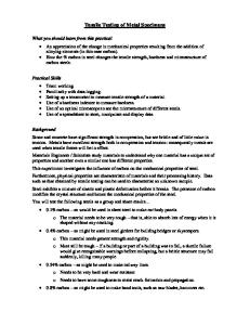
be easily made out of a thin-walled cannula that can be plastically deformed to modest stresses (as shown in Fig. 1c for a regular walled tube). To address these challenges, an alternative method for testing metal tubes has been with insertion of metal plugs on either ends of the test specimen, as referenced by ASTM (A 370) (Figure 1d). The plugs help to avoid the ends being crushed by the grip jaws, and allows extension of only the in-between tube region; ultimately causing fracture in the tube in the gage region, and not at the tube grip interface. At present, stainless steel cannulae have been successfully tensile tested by using metal inserts of smaller OD (outer diameter). Note: In order to ensure that the metal plugs do not slide with respect to the cannula as it is being pulled during the test, adhesive is applied onto the surface of the metal plugs and inserted carefully inside the testing cannula to create a strong bond between the two metal surfaces. However, this method cannot be extended to finer, thin-walled cannulae, such as a 32G thin-walled cannulae with outside diameter of 237 µm and inside diameter of 167 µm, as it is impractical to find smaller metal plugs that can be used as inserts for the 32G. Additional problems also lie in gripping such a fine cannula in the Instron® machine using conventional gripping jaws.
Fig. 1. (a), (b), (c) and (d) Typical shapes of tensile specimens used for tensile testing Taking cue from the shape of the dog-bone specimen it is anticipated that instead of using metal plugs as inserts, bigger metal tubes with its ID (inner diameter) matching that of the OD of the 32G can be used on the outside as sleeves in the grip sections. A schematic of such a design is shown in Fig. 2, where a 32G cannula is jacketed by two 24G tubes.
Fig. 2. Schematic of a tensile testing specimen of 32G Cannula
17
Mechanical Testing and Diagnosis, ISSN 2247 – 9635, 2014 (IV), Volume 2, 16-22
A 24G cannulae is chosen as its inner diameter of 260 µm matches the outer diameter of the 32G cannulae. A strong bonding between the two metal concentric tubes is desired to create adequate bearing area and shear transfer in the grip region.One way of validating such a behavior (and a very useful one!) is to perform tests with different gage lengths. The uniaxial stress-strain curve generated from such tests should be independent of the dimensions of the gage length. At present, two methods were explored to bond the tubing of interest to the jacket tubing: (i) glue, and (ii) solder.All studies were conducted on the cannulae processed under the same conditions. This new tensile testing design described here for 32G has not been reported anywhere else, and therefore, forms the basis for this paper.
2. EXPERIMENTAL METHODS 2.1 Jacket Bonding with Glue From a long 32G 304 stainless steel cannula, at first, 4.5 inch, 4.0 inch, and 3.5 inch pieces were cut using a pair of plyers. Then, Instant Krazy® glue was applied on either sides of the cut pieces and two 1.5 inch 24G tubes were slid quickly over it to form a strong bond between the two metal parts. Finally, a second set of 1.5 inch tubes of 20G were used around the 24G for additional encapsulation; bonded also using the same glue. The resulting specimens with gage lengths of 1.5 inch, 1.0 inch and 0.5 inch were tensile tested in Instron machine until failure. It may be mentioned that other gage lengths were not tried due to difficulty in making and/or handling them. 2.2 Jacket Bonding with Solder Instead of gluing and using two pairs of sleeves, 32G cannulae of 4.5 inch, 4.0 inch, and 3.5 inch in length were sleeved by a single set of 1.5 inch 24G tubes on either sides of the cannula, and bonded by soldering both the ends of thetubes to the cannula. The exact procedure is described in detail in the Appendix. As before, the specimens with gage lengths of 1.5 inch, 1.0 inch and 0.5 inch were similarly tensile tested in Instron machine until failure. 3.
RESULTS AND DISCUSSION
For both the two bonding conditions (i.e., gluing and soldering) it was observed that the specimens broke in the gage section at the end of the tensile test and not at the interface of the gage section and the grip joints (for example, see Figure 1F in the Appendix), thereby indicating a strong metal-metal bond for both the cases. 3.1 Effect of Glue The stress-strain curves for different gage lengths are shown in Figure 3 for the 32G. A considerable variation in the stress-strain curves was observed, with maximum variation of 18% in ultimate tensile strength and 52% in failure strain between the 1.0” and 1.5” gage lengths. These samples exhibited limited strain hardening as revealed by the flatness of the stress-strain curve that may be due to the limited wall thickness ~ 35 m of such thinwalled stainless steel needles. 3.2 Effect of Solder The stress-strain cuves generated from the tensile specimen is shown in Fig. 4 for different gage lengths. Here, the maximum percentage variation in ultimate tensile strength
18
Mechanical Testing and Diagnosis, ISSN 2247 – 9635, 2014 (IV), Volume 2, 16-22
Figure 3. Stress-Strain relationship for 32G using gage lengths of 0.5”, 1.0” and 1.5”. The tensile specimen was prepared using two sleeves of 20G and 24G tubes around the 32G cannula at the grip ends, and bonded using Instant Krazy® glue. The measured values for elastic modulus, 0.2% yield strength, ultimate tensile strength, and % elongation to failure are 126 ± 27 GPa, 990 ± 123 MPa, 1118 ± 112 MPa, and 6.47 ± 1.67, respectively.
Fig. 4. Stress-Strain relationship for 32G using gage lengths of 0.5”, 1.0” and 1.5”. The tensile specimen was prepared using a single sleeve of 24G tube around the 32G cannula at the grip ends, and soldered at the both the ends. The measured values for elastic modulus, 0.2% yield strength, ultimate tensile strength, and % elongation to failure are 125 ± 6 GPa, 961 ± 23 MPa, 1086 ± 46 MPa, and 6.3 ± 0.9, respectively. A significantly lesser variation in the stress-strain curves was noticed in Fig. 4, when comparing to Fig. 3.
19
Mechanical Testing and Diagnosis, ISSN 2247 – 9635, 2014 (IV), Volume 2, 16-22
and failure strain is around 8% and 27 %, respectively, between 1.0” and 1.5” gage lengths.These values are lower than those with the glue. It should be pointed out that ASTM and ISO standard recommend five (5) tests under the same condition;whereas, here only one (1) test was conducted under a specific sample type condition. Therefore, the spread in the values measured here may not followthe standards. In order to assess the veracity of the tensile strength values obtained from the stressstrain curves (mentioned in Figures 3 and 4), a comparison was made between these results and ones obtained from other sources i.e., through micro-hardness measurements. Since these specimens had been mechanically processed prior to their final dimensions, it was not possible to compare these values directly to the ones found in the literature. However, a micro-hardness value of 370 ± 6 HV (or, 3629 ± 59 MPa) was obtained by performing hardness measurements on cross-sectional samples of 32G cannula. For stainless steel metals, it has been reported that the micro-hardness and the ultimate tensile strength are related by a constant factor of around 0.34 [1], which results in a value of 1234 ±16 MPa, according to the hardness measurement. This value is in the vicinity of the measured values obtained from the stress-strain curves for both the bonding conditions. Note: The reported elastic constant of 304 stainless steel is around 193 GPa, whereas the present tests gave a value of around 126-125 GPa. Such a discripancy may be due to the non-delicate nature of the test, i.e., the test was not specifically designed for determining the elastic constant. Though the average values of the mechanical properties determined from the stressstrian curve were similar for both gluing and soldering, it is noticed that soldering the ends of the tubes produced a much smaller variation in measurment, which might thereby indicate a better adhesion between the parts and allowing smoother transfer of the grip extension to the gage region. Hence, the current tensile specimen,indicated in Figure 2 with soldered ends, can beusedfor performing tensile tests. 4. CONCLUSION Tensile specimens of 32G cannulae were made by encasing the cannulae with bigger 24G tubes at the ends and soldered. The bigger 24G tubes provided better grips by the Instron grip jaws. Reliable stress-strain curve was obtained with such a material design, and fracture was noticed in the gage region at the end of the tensile test. It is believed that such a design would allow tensile tests on even finer gages of cannulae. REFERENCES 1. J.R. Davis, Tensile Testing, ASM International, 2004. APPENDIX Tensile test specimens of 32G cannula were prepared by taking a 4” cut specimen of 32G cannula and inserting into a 1.5” cut piece of 24G tube, completely. The two metal pieces were soldered on both ends. Next, the other end of cannula was inserted inside another 1.5” 24G tube and, similarly, soldered. Items used for soldering were Kester Formula 815 Acid Flux, Kester Solid Wire Solder 50/50, Basic Soldering iron with Flat Tip (not pointed), and a small table vise. A pair of gloves was used for handling. The basic steps of soldering are: 1. Placing soldering iron in vice plug-in and allowing the iron to reach operating temperature of around 360 °F in approximately 5 minutes.
20
Mechanical Testing and Diagnosis, ISSN 2247 – 9635, 2014 (IV), Volume 2, 16-22
2. 3.
Dipping soldering wire into flux and apply it to the tip of pre-heated solder iron. Inserting 32G cannula into 24G tube and apply a drop of flux to the top of the union. Note: It is desirable to have a visible amount of liquid flux present as this will help “wick” the molten solder to fill the gap between the two parts. 4. Touching the assembly to the tip of the soldering iron. The molten solder should flow and join the two pieces together. If not, apply another drop of flux and repeat the process. Do it for both the ends of the two tubes. This technique may require some practice to perfect but is highly effective for joining two metal sections together. The following images, from Figures A.1 through A.6, show the specimen assembly before and after the tensile test.
Fig. A.1
Fig. A.2
Fig. A.3
21
Mechanical Testing and Diagnosis, ISSN 2247 – 9635, 2014 (IV), Volume 2, 16-22
Fig. A.4
Fig. A.5
Fig. A.6
22