A LOW POWER PREAMBLE DETECTION METHODOLOGY FOR PACKET BASED MODEMS Kiran Gunnam, Pankaj Bhagawat, Gwan Choi, Mark Yeary* Dept. of Electrical Engineering, Texas A&M University, College Station, TX-77840 * Dept. of Electrical and Computer Engineering, University of Oklahoma, Norman, OK-73109 ABSTRACT In order to achieve frame synchronization in packetbased communication systems, a known sequence (preamble) is sent at the beginning of each packet. This paper presents a low power scheme for preamble detection using dynamic precision configuration. The proposed scheme is based on the observation that signal processing algorithms at the front end (including mixer, Square root raised cosine (SRRC) matched filter and code matched filter(CMF)) of the receiver, can be operated with minimum precision during the acquisition phase without incurring significant acquisition performance degradation. The result is an acquisition system design that consumes less than 25% of power dissipation that is consumed by other typical implementations. Keywords: Packet Detection, Carrier Acquisition, 802.11b, 802.15, Burst Modem, Packet based Modem EXTENDED SUMMARY Hardware implementation of synchronization algorithms for many common wireless standards, such as Bluetooth, 802.11a and 802.11b take up more than 15% of the die area and total chip power comsumption [1]. In this communication, we report a low power, area efficient, high speed hardware implementation for frame synchronization. The idea is based on a systematic search for optimal bit precision for detecting the correlation peaks in presence of noise. As we would demonstrate, this will reduce, both, the acquisition time and power consumption of the hardware. Signal processing algorithms at the receiver, till the SRRC filter and pre-amble acquisition is usually implemented in application specific integrated circuits (ASICs) or FPGA as these are computationally intensive. The coherent receiver which operates at the symbol rate is usually done in a Digital Signal Processor. In Fig. 1 we show block diagram of a typical receiver. Fig. 2 gives an explanation for the typical acquisition operation in a flowchart format. Also, in Table.2 we have described functionalities of various blocks. PRE AMBLE DETECTION In most commercial systems the SRRC filter, even during the acquisition phase, operate at 12 bit precision
[4-5]. However, for computing the correlation, only one bit (the sign bit) is used. Obviously, rest of the 11 bits serve no purpose, and hence contribute to unnecessary power consumption. Under low signal to noise ratio (SNR), however, this approach does not compute autocorrelation of the preamble sequence accurately, thus leading to loss in acquisition rate. Since only one bit is used to compute the correlation, we might as well operate the front end of the receiver and SRRC filter at lower precision. Lowering the bit precision, however, causing quantization noise to affect the system acquisition performance. In this work we show that four bit quantization for SRRC filter and the front end is enough to get performance close to that of a system with 12 bit quantization. The key observation is, that the SRRC and chip matched filter, which computes the correlation with pre-amble, on the two most significant bits (MSB) of the SRRC filter outputs causes no performance loss. As mentioned earlier, lower precision leads to lower acquisition rate. To alleviate this problem we exploit the fact that repetition of Barker sequence improves acquisition rate by reducing the false detection probability and improving the detection probability [2]. DISCUSSION Our results on 802.11b implementation show that the proposed method reduces the power consumption of the acquisition block by a factor of six compared to some industry implementations [4]. Table.1 shows that comparative reductions in operation count for acquisition. Table.2 shows the power estimation for operating the acquisition block in the search mode. However note that the acquisition block will be activated either on a periodic basis during the sleep mode and/or based on simple RF energy detector. Table.3 shows the power savings comparison for the proposed and work in [4]. The power dissipation of the acquisition block if done in full precision is around 1.2 W. The work in [4-5] applies the optimizations at the correlator only- this will have power savings of 8%. This work achieves the savings of 76% with respect to power dissipation of Full precision and consumes less than 25% of the power dissipation that is consumed by other typical implementations. Note that since the comparisons are
done on FPGA platform, the power dissipation numbers are very high when compared to the numbers reported by ASIC implementations. Bit error rate (BER) performance is not affected by this scheme as the receiver is operated with 12bit precision after the packet is acquired. Also, the acquisition time still remains 4µs (4 packets), to meet the requirement of 802.11b standard. Indication of the preamble detection will be communicated to the medium access control (MAC) to ensure that any planned transmission is backed off to avoid possible collision. Since 802.11b preamble is longer, 128 barker sequences, we will use this for further validation activities without turning on the full precision receiver. CONCLUDING REMARKS A low power frame acquisition scheme with packet detection rate close to 1 is presented. An efficient and fast multi-level decision approach based on running a low precision version of the receiver front end along with the acquisition block is implemented in hardware for preamble detection. This approach can be used to reduce power requirements for other wireless modems such as one used in 802.15 standard. 6. REFERENCES [1] M. Ammer, “Low Power Synchronization for Wireless Communication,” December, 2004, Ph.D.
Thesis, Department of EECS, Univ. of California, Berkeley. [2] S. Lee and J. Ahn, “Acquisition performance improvement by Barker sequence repetition in a preamble for DS-CDMA systems with symbol length spreading codes,” IEEE Transactions on Vehicular Technology, vol. 52, issue 1, pp. 127-131. January 2003. [3] H. Meyr, M. Moeneclaey, and S. Fechtel, Digital Communication Receivers: Synchronization, Channel Estimation and Signal Processing. 2nd Edition. Wiley Press, 1997. [4] Altera Corporation, Direct Sequence Spread Spectrum (DSSS) Modem Reference Design, issue A-FS14-1.0, September 2001. Online at: www.altera.com/ literature/ fs/ fs14_dsss. pdf . [5] Intersil, HFA3861B Direct Sequence Spread Spectrum Baseband Processor, datasheet, issue FN4816.2, February 2002. Online at: www. datashe etcatalog.com/datasheets_pdf/H/F/A/3/HFA3861B.shtml .[6] Texas Instruments, Information on Data Converters Online at :http://focus.ti.com/analog/docs/dataconverter shome.tsp?familyId=82&contentType=4
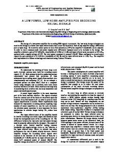
RX Samples at Zero IF
RX Samples @IF IF RF Front End
ADC
RX_Chips Oversampled by 4
I
SRRC Filter with Decimation 4
Q
SRRC Filter with Decimation 4
[1 0 -1 -0]
Fs=4*Fif [0 1 0 -1] Cosine of Fs/4 Sine of Fs/4
FIG. 1 802.11b Digital Front end, Fif = 22MHz
2 Bit Parallel Correlator (Tree Based Adder Structure)
SQUARE 6 bit by 6 bit Adder 12 bit
2 Bit Parallel Correlator (Tree Based Adder Structure) I and Q Samples from Filter/Decimator
SQUARE 6 bit by 6 bit
FIG 2: CORRELATOR
Threshold and Periodicity Check
Simple Energy detector in RF front end or a Periodic Wakeup triggers a search.
Perform Acquisition using 4 bit ADC, and SRRC and 2-bit CMF If periodicity of 4 peaks is found, indicate channel sense to MAC layer
Check for periodicity of 10 more peaks in Low precision mode
Enable RX in full data path mode
Check for at least one peak in Full precision mode
Declare Packet acquired and continue decoding preamble for AGC, Channel estimation, Initial frequency and phase offset estimation. Once preamble is decoded correctly, the baseband receiver can be turned on.
If any of the above sequential steps fail, receiver goes to the sleep mode
FIG 3: FLOW CHART FOR ACQUISITION
Table 1: Hardware requirements for Modules in Front End. Target Device: XC2VP40-6FG676 Logic Utilization
12 bit Code Matched Filter
2 bit Code Matched Filter
SRRC MAC Filter 12 bit
Number of Slices Number of Slice Flip Flops Number of 4 input LUTs Number of MULT18X18s
724 673 1268 8
162 193 248 2
1511 2606 1424 12
SRRC Filter 4 bit (Distributed Arithmetic) 224 392 352 0
Table 2: Power Dissipation of Front End Modules during acquisition. Power of individual modules is estimated using the Xilinx Power estimation tool .For ADC power analysis is based on data from [6]. Module ADC
12 bit Precision 360 mW 12 bit samples ~0 mW 12 bit 2’s complement 730 mW 12 bit Samples and filter coefficients Xilinx MAC Filter
4 bit Precision 120 mW 4 bit samples ~0 mW 2 bit 2’s complement 145 mW 4 bit samples and 4 bit coefficients Xilinx Distributed Arithmetic Filter
CMF
111 mW 12 bit
22 mW 2 bit
Total Power of Acquisition Block
1201
287 Power savings: 76%
Mixer SRRC
Functionality 88 M Samples per second (MSPS). 1 Channel Fs/4 Mixing. 2 Channels. Down converts to Baseband. Number of coefficients = 48, 2 Channels. Provides receive pulse shaping. Input Sample rate: 88 MSPS. Output Sample rate: 44 MSPS Operating frequency: 196 MHz For Low precision filter, some of the coefficients are zeros and Xilinx core generator exploits this to implement distributed arithmetic filter. Both filters use the same input and output buffers. Only one of them is active at any time. Performs de-spreading operation with Barker sequence and computes the correlation. Correlator is built with binary tree adder/subtractor followed by squaring circuits on both I and Q channels to compute the magnitude. Input Sample: 44 MSPS Output: 44 M correlation per second Operating frequency for both filters is 44 MHz Detects the frame start and is composed of above modules which follows the RF front end
Table 3: Power Savings Comparison. *-estimated on Xilinx FPGA platform since [5] is based on Altera FPGA implementation. Metric Total Power Savings
Full Precision 1201 mW 0%
[5]* 1100 mW 8%
Proposed 287 mW 76%