60T Series Snap-Action Temperature Controls
Snap-Action Temperature Control The 60T line of 3/4” (19mm) bimetal disc temperature controls from Therm-...
Snap-Action Temperature Control The 60T line of 3/4” (19mm) bimetal disc temperature controls from Therm-O-Disc offers proven reliability in a versatile, cost-effective design. The snap-action of the temperature sensing bimetal disc provides high-speed contact separation, resulting in exceptional life characteristics at electrical loads up to 25 amps at 240VAC. A wide variety of terminal and mounting configurations are available for maximum design flexibility. This unsurpassed flexibility and time proven reliability, at an affordable price, has made the Therm-O-Disc 60T the most popular and widely applied temperature control in the major appliance and heating/air conditioning industries.
Additional Features and Benefits Additional features and benefits of the 60T include: • Available with automatic and manual reset SPST (Single Pole, Single Throw) or automatic reset SPDT (Single Pole, Double Throw) switch configurations. • Welded construction for integrity of current-carrying components. • Available with an exposed or enclosed bimetal disc for either increased thermal response or protection from airborne contaminants.
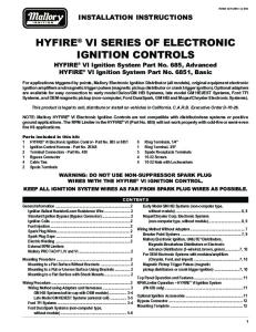
Switch Actions and Typical Applications The 60T is available in three switch actions: • Automatic Reset SPST • Automatic Reset SPDT • Manual Reset SPST (Trip Free) Automatic Reset SPST – In this design, the switch can be built to either open or close its electrical contacts on temperature rise. Once the temperature of the bimetal disc has returned to a specified reset temperature, the contacts will automatically return to their original state. Typical uses of this construction include limiting and regulating temperatures in clothes dryers and heating/air conditioning systems (see figures 1 and 2).
1
0.170 (4.3)
1.688 (42.9)
T.O.D.
2.00 (50.8)
1.563 (39.7)
1.63 (41.4)
1.08 (27.4) 0.39 (9.9)
Ø0.93 (Ø23.6)
Airstream Mounting Figure 1 0.172 (4.4)
T.O.D.
1.562 (39.7)
1.75 (44.5)
0.42 (10.7) 1.63 (41.4)
1.08 (27.4)
Ø0.93 (Ø23.6)
Surface Mounting Figure 2 Dimensions are shown in inches and (millimeters).
2
Automatic Reset SPDT – This design is the same as the SPST described above with the addition of an auxiliary contact which makes circuit upon the opening of the main contacts and breaks circuit when the main contacts reset. Refer to the “General Electrical Ratings” chart for rating limitations on the auxiliary contacts. Typical uses of this construction include fan speed changeover at a specified temperature and lighting of an indicator lamp when an abnormal temperature condition has been reached (see figure 3). CAUTION . . . When designing a circuit for a single pole, double throw control, an electrical load must be applied to terminal number 2 and/or 3 to avoid a possible short circuit condition.
Manual Reset SPST – This design is available only with electrical contacts which open on temperature rise. The contacts may be manually reset after the control has cooled below the open temperature calibration. This construction is classified as “M2 Trip Free” by the approval agencies. A patented design holds the contact open in the event the reset button is held in the depressed position in an attempt to defeat the manual reset function of the thermostat. Typical uses include any temperature limiting application where operation of the thermostat should result in the user or service personnel having to attend the unit (see figure 4). 0.170 (4.3)
1.688 (42.9)
T.O.D.
1.563 (39.7)
2.00 (50.8)
1.63 (41.4)
1.16 (29.5) 0.39 (9.9)
Ø0.93 (Ø23.6)
SPST Manual Reset – Airstream Mounting Figure 4 Dimensions are shown in inches and (millimeters).
Thermal Response An exposed or enclosed bimetal disc may be specified with any of the airstream or surface mounting configurations. The enclosed disc construction provides greater protection than the exposed disc construction, keeping airborne contaminants such as dirt and dust from entering the control. It also protects the bimetal disc from possible physical damage during assembly and in the final application. In applications where faster response to radiant heat is required, an exposed bimetal disc or an optional black oxide mounting finish may be specified.
4
Mounting Configurations The 60T is available in an airstream or a surface mount configuration: Airstream Mounting – This mounting configuration positions the bimetal disc through a hole in the mounting surface to sense temperature within an enclosure such as a heater box or air duct. The standard configuration (see figure 1) positions the bimetal disc .39” (9.9mm) into the airstream while an optional version (see figure 5) positions the bimetal disc .78” (19.8mm) into the airstream. Airstream configurations may be specified with a flange (see figure 5) or without a flange (see figure 6) to suit specific application needs. Surface Mounting – This optional mounting configuration positions the bimetal disc firmly against the mounting surface to sense the actual mounting surface temperature (see figure 2).
1.69 (42.9)
X
X
0.17 (4.3)
314416 T.O.D.
T-O-D
60T81
2.00 (50.8)
1.56 (39.7)
8402-134 DATE L265-30F
X
X 1.63 (41.4)
1.51 (38.4) 0.78 (19.8)
Ø0.94 (23.9)
SPST Airstream Mounting – Deep Disc Cup Figure 5
T.
500105 T-O-D 60TE03 1-3 25(3.3)/250 1-2 5(2)/250
Ø31.1 (1.25)
322.5992 DATE L163-17C
57.4 (2.26)
29.9 (1.18) 8.8 (0.34) Ø23.7 (0.93)
SPDT Airstream – No Flange Figure 6 Dimensions are shown in inches and (millimeters).
5
Terminal Configurations Standard Terminals – Standard terminations for the 60T are .250” x .032” (6.3 x .8mm) tin-plated brass blade terminals formed at 90 angular degrees to the thermostat mounting surface. Terminal angles of 0 and 30 degrees can also be provided (see figure 7).
Blade Terminal Angles 90°Terminals
0°Terminals
30°Terminals Figure 7
Non-Standard Terminals – The 60T can also be provided with a variety of optional terminals. Some of the more common variations include .188” (4.8mm) blade terminals, 8-32 screw terminals and fork terminals. Unique variations such as double or offset blade terminals are also available. Terminal Orientation – For added flexibility, the orientation of the terminals with respect to the mounting bracket can be specified in 45 angular degree increments (see figure 8).
Terminal to Mounting Bracket Orientation
Terminals 90° to mounting holes (standard)
Terminals 45° clockwise to mounting holes Figure 8
6
Terminals 45° counterclockwise to mounting holes
Calibration Temperatures, Differentials and Tolerances To use the calibration chart, locate the range in the left hand column, in which the highest calibration set point (open or close) falls. Then, locate across the top, the range in which the nominal differential falls. The standard open and close set point tolerances are shown where the two columns converge. The chart also indicates what differentials are available in each of the calibration set point ranges. Tighter open and close tolerances are available at added cost. Thermocouple samples can be provided to assist in determining the appropriate calibration temperature for specific application. For more information on tightened tolerances or availability of differentials not listed in the chart, please consult one of our sales engineers.
Calibration Temperatures, Differentials and Standard Tolerance of the 60T Series Nominal Differentials (temperature difference between nominal open and close set point)
Highest Calibration Set Point Range (Open or Close)