R820 REV2 SERIES SCR POWER CONTROLS Product overview
The Viconics R820 series SCR power controls are designed for cost effective, precise modulation of electric loads for most electric heating applications. (Applicable on resistive loads only) The R820 series consists of SCR’s power controls, c/w factory assembled heatsink for surface or in-panel mounting.
Models available
Model No.
Voltage Range
Phase
Max Current
R820-211-REV2 R820-213-REV2 R820-321-REV2 R820-323-REV2 R820-341-REV2 R820-343-REV2 R820-421-REV2 R820-423-REV2 R820-441-REV2 R820-443-REV2 R820-471-REV2 R820-621-REV2 R820-623-REV2 R820-641-REV2 R820-643-REV2 R820-671-REV2
24 - 240 Volts AC 24 - 240 Volts AC 24 - 347 Volts AC 24 - 347 Volts AC 24 - 347 Volts AC 24 - 347 Volts AC 24 - 480 Volts AC 24 - 480 Volts AC 24 - 480 Volts AC 24 - 480 Volts AC 24 - 480 Volts AC 24 - 600 Volts AC 24 - 600 Volts AC 24 - 600 Volts AC 24 - 600 Volts AC 24 - 600 Volts AC
1 3 1 3 1 3 1 3 1 3 1 1 3 1 3 1
10 Amp 10 Amp 25 Amp 25 Amp 45 Amp 45 Amp 25 Amp 25 Amp 45 Amp 45 Amp 75 Amp 25 Amp 25 Amp 45 Amp 45 Amp 75 Amp
Features ⇒
Feature Complete assembly with factory installed heat sink.
⇒
Designed for surface or panel mounting
⇒
UL Recognized
⇒
CSA approved for Canada and USA Status LED High quality assembly with 2 year warranty Full line of matching peripheral temperature controllers
⇒ ⇒ ⇒
⇒ ⇒ ⇒ ⇒ ⇒ ⇒ ⇒
Benefit Reduced total installation cost Covers wider array of application with same component. Easily integrated into complete assembly requiring industry listings. Trouble free approval process Quick field troubleshooting. Reduced field service calls. Simplified component sourcing and matching for reliable operation
They are compatible with many industry standard signals. A typical application would be to control a modulating electric duct heater with a 0 to 10 Vdc control signal from an analog room thermostat. The R820 power controller also contain four dip switch to adjust to the following control signals: • 0 to 10 Vdc control signal ( 2 to 10 Vdc control range ) • 4 to 20 mA control signal • 0 to 135 Ω control signal
LIT-R820_REV2-E03
1
Power modules installation Important. All external safety devices like: contactors, relays, flow switch & thermal protections are to be supplied and installed by other. When the SCR is installed inside a panel, the enclosure needs to be adequately louvered for proper ventilation and heat dissipation. Call the factory for the derating amperage curves for these specific applications. Electronic controls require special care for wiring and startup. To avoid problems, carefully follow the procedures below. Look at the wiring diagrams, and study them carefully. Be sure that you understand how the system is supposed to work. A) Location: 1- Can be installed inside a louvered approved cabinet or with the heatsink mounted externally. 2- Must be installed away from excessive heat source. 3- Nothing must restrain air circulation to the heatsink. B) Installation: 1- If installed completely inside a cabinet, use the mounting tabs on the heatsink to secure the SCR to the back plate of the panel. 2- If installed with heatsink outside the cabinet, use the proper model mounting template for the cut out dimensions and to check for mounting obstructions. 3- Respect mounting orientation ( this side up ). 4- Mount the heatsink vertically on the side of the cabinet for proper heat dissipation. 5- Do not relocate the power switching modules on the heatsink. R820 Installation and Dimensions • • • • • •
Mounting instructions & templates are available from the factory. The cutout templates include holes position for heatsink attachment to the electrical cabinet Single phase R820 will have 2 mounting screw, 1 on each side. Three phase R820 will have 4 mounting screw, 2 on each side. Respect mounting orientation ( this side up ). Mount the heatsink vertically on the side of the cabinet for proper heat dissipation. If mounted on top or bottom of the cabinet, derate maximum usable amperage by 25%. Do not relocate the power switching modules on the heatsink. R820 single phase R820-211-REV2 R820-321-REV2 R820-341-REV2 R820-421-REV2 R820-441-REV2 R820-471-REV2 R820-621-REV2 R820-641-REV2 R820-671-REV2
R820 three phase R820-213-REV2 R820-323-REV2 R820-343-REV2 R820-423-REV2 R820-443-REV2 R820-623-REV2 R820-643-REV2
A 5.25 " 5.25 " 5.25 " 5.25 " 5.25 " 5.25 " 5.25 " 5.25 " 5.25 "
A 5.25 " 5.25 " 5.25 " 5.25 " 5.25 " 5.25 " 5.25 "
B 4.50 " 4.50 " 6.50 " 4.50 " 6.50 " 10.00 " 4.50 " 6.50 " 10.00 "
C 2.56” 2.56” 2.56” 2.56” 2.56” 2.56” 2.56” 2.56” 2.56”
D 3.00 " 3.00 " 3.00 " 3.00 " 3.00 " 3.00 " 3.00 " 3.00 " 3.00 "
E 3.75 " 3.75 " 3.75 " 3.75 " 3.75 " 3.75 " 3.75 " 3.75 " 3.75 "
Weight 1.80 1.80 2.40 1.80 2.40 3.50 1.80 2.40 3.50
B 6.50 " 6.50 " 10.00 " 6.50 " 10.00 " 6.50 " 10.00 "
C 2.56” 2.56” 2.56” 2.56” 2.56” 2.56” 2.56”
D 3.00 " 3.00 " 3.00 " 3.00 " 3.00 " 3.00 " 3.00 "
E 5.75 " 5.75 " 5.75 " 5.75 " 5.75 " 5.75 " 5.75 "
Weight 2.60 3.70 3.70 2.65 3.70 2.65 3.70
LIT-R820_REV2-E03
2
DIP Switch Adjustments per applications INPUT SIGNAL 0 to 10 Vdc control signal ( 2 to 10 Vdc control range ) 4 to 20 mA control signal 0 to 135 Ω control signal
SWITCH #1 Off Off On
SWITCH #2 Off Off On
SWITCH #3 Off On Off
SWITCH #4 On Off Off
Typical applications
0 To 10 Vdc Room Or Duct Thermostat Control Dip switch position 0 to 10 Vdc control signal
S1 Off
S2 Off
S3 Off
S4 On
2 V dc = 0% capacity 10 V dc = 100% capacity L1
1 2
Modulating R oom T hermos tat
3
0 to 10 V dc
C ommon 24 Vac 0 to10 Vdc output
L2
Modulating S upply A ir C ontrol T hermos tat 0 to 10 V dc
2nd S S R on 3 phas e models only
L3
0 To 10 Vdc From a Building Automation System Dip switch position 0 to 10 Vdc control signal
S1 Off
S2 Off
S3 Off
S4 On
2 V dc = 0% capacity 10 V dc = 100% capacity L1
1 2
3
Modulating S ignal F rom B A S S ys tem 0 to 10 V dc
+
L2
L3
LIT-R820_REV2-E03
2nd S S R on 3 phas e models only
3
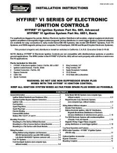
0 To 135 Ω Room Or Duct Thermostat Control Dip switch position 0 to 135 Ω control signal
S1 On
S2 On
S3 Off
S4 Off
0 O hms = 0% capacity 135 Ohms = 100% capacity L1
1 2
Modulating R oom T hermos tat
3
50 60 70 80
W
0 to 135 Ohms
90
R B
L2 50 60 70 80 90
Modulating S upply A ir C ontrol T hermos tat 0 to 135 Ohms
2nd S S R on 3 phas e models only
L3
4 To 20 mA From a Building Automation System Dip switch position 4 to 20 mA control signal
S1 Off
S2 Off
S3 On
S4 Off
4 mA = 0% capacity 20 mA = 100% capacity L1
1 2
3
+ Modulating S ignal F rom B A S S ys tem 4 to 20 mA L2
L3
LIT-R820_REV2-E03
2nd S S R on 3 pha se models only
4
24 Vac Power& Wiring • •
It is not necessary to ground any leg of the transformer to earth with the controller card. The controller uses internally a half wave rectifier bridge. On 0 to 10 Vdc control signal, the reference of the control signal is the Common of the power supply of the SCR controller card. Use a Class 1 ( properly fused ) or Class 2, CSA or UL recognized transformer.
•
High voltage Wiring General cautions: • •
High voltages are present on the terminals of these devices. Please read all the instruction in this manual carefully. The 45 & 75 Amps models need to be wired with the supplied high voltage lugs. Attach the wire to the lug first, and then screw the lug to the power module. Have the wiring done by a qualified and skilled professional. High voltage and amperage can be fatal. All wiring must conform to national electrical code regulations. The instrument must be wired before applying power. Protect circuits with semi conductor fuses. For in panel installation, derating amperage curves are available from the factory.
• • • • • •
Specifications Operating Conditions: Thermostatic protection: Power supply:
0°C to 80°C ( 32°F to 176°F ) / 0 % to 95 % R.H. non-condensing See power derating curves document Self-resetting. Auto shut off when SCR ambient temp. is above 82°C ( 180°F ) 24 Vac -15%, +10% 50/60 Hz; 2 VA Use a Class 1 ( properly fused ) or Class 2, CSA or UL recognized transformer.
Troubleshooting 1 2 3 4 • • • • • • • • • • •
5 6 7 8
Check Check general wiring, as per heater manufacturer diagram Be sure you understand the system and its normal operation Verify high voltage power supply wiring Verify that correct voltage is present at the heater with proper wire size Verify low voltage 24 Vac power supply wiring 24 Vac is present at terminals 1 & 2 of the R820 SCR Create or simulate 100 % heating demand Using present control system R820 Configured for 0 to 10 Vdc input signal Signal between terminals 1 & 3 is 10 Vdc or superior Dip switch properly configured: S1=Off, S2=Off, S3=Off & S4=On Be sure that the polarity is correct and not reversed + to +, - to Red status LED on SCR is on 100 % of the time R820 Configured for 4 to 20 mA input signal Signal between terminals 1 & 3 is 20 mA or superior Dip switch properly configured: S1=Off, S2=Off, S3=On & S4=Off Be sure that the polarity is correct and not reversed + to +, - to Red status LED on SCR is on 100 % of the time R820 Configured for 0 to 135 Ω input signal Signal between terminals 1 & 3 is 135 Ω or superior Dip switch properly configured: S1=On, S2=On, S3=Off & S4=Off Red status LED on SCR is on 100 % of the time Verify amperage consumption of the heater Red status LED on SCR is on 100 % of the time Verify & correct 24 Vac power supply to the SCR Verify low voltage fuses, protections, flow switch, etc……… Verify control wiring & control signal Correct control signal is present at the SCR Check polarity of control signal Verify fuses & all protections & contact the heater manufacturer
Viconics Electronics Inc. 9245, Langelier Blvd, St-Leonard, Quebec, Canada H1P 3K9 028-5011
LIT-R820_REV2-E03
Important Notice: These instruments have undergone rigorous tests and verifications prior to shipment to ensure proper and reliable operation in the field. However, like other such products, they are subject to failure. It is therefore the responsibility of the installer / user / electrical panel designer to incorporate safety features and devices ( such as relays, flow switch, thermal protections, etc.. ) to protect the entire system from catastrophic failure.
www.viconics.com
[email protected] 5