View Dependent Mesh Streaming based on Geometry Image and JPEG 2000 Standard Nein-Hsiung Lin* Ting-Hao Huang*
Bing-Yu Chen†
Yung-Yu Chuang‡ Ming Ouhyoung‡
National Taiwan University
*{ppbb,richardg}@cmlab.csie.ntu.edu.tw
†
[email protected]
ABSTRACT
For PC and even mobile devices, video and image streaming technologies, such as H.264 and JPEG/JPEG 2000, are already mature. However, the 3D model streaming technology is still far from practical use. Therefore, we wonder if 3D model streaming can directly benefit from current image and video streaming technologies. Hence, in this paper, we propose a mesh streaming method based on geometry image [3] to represent a 3D model or a 3D scene and integrate it into an existed client-server multimedia streaming server. In this method, the mesh data of a 3D model is first converted into a JPEG 2000 (J2K) [7] image. Based on the JPEG 2000 streaming technique, the mesh data can then be transmitted over the Internet as a mesh streaming. Furthermore, the view-dependent issue is also taken into account. Moreover, since this method is based on JPEG 2000 standard, our system is much suitable to be integrated into any existed image and video streaming system.
Categories and Subject Descriptors I.3.2 [Computer Graphics]: Graphics Systems – distributed/network graphic; I.3.5 [Computer Graphics]: Computational Geometry and Object Modeling – curve, surface, solid, and object representations.
General Terms Standardization.
Keywords
‡
{cyy,ming}@csie.ntu.edu.tw
Therefore, in this paper, we propose a new mesh streaming method by utilizing the benefits of JPEG 2000. This method takes the advantage of the fact that a 3D model or a 3D scene can be represented by a geometry image [3]. This could reduce the problem of 3D mesh streaming and transfer it to 2D image streaming. There are also many 2D image compression methods that can be used to further downsize the file of the geometry image. This paper made use of the JPEG 2000 [7] compression due to some of its good characteristics, such as ROI (Region Of Interest), progressive compression, multiple components, etc. Moreover, since this method is based on JPEG 2000, which is a famous standard, our system is much suitable to be integrated into any existed image and video streaming system. Based on our mesh streaming method, during the downloading process, the user can first obtain an approximate shape and then the 3D model will become clearer when more data is received. Besides the progressive transmission, the view-dependent issue is also taken into account. Hence, the most significant part of the 3D model or the part faced to the user will be refined earlier.
2.
Related Work
2.1 Mesh Streaming and Compression 3D model has become more and more sophisticated, as well as its file size. Hence, many previous works are focus on shortening the latency caused by the model transmission over the Internet and several mesh streaming methods have been proposed for solving this problem.
Geometry Image, Mesh Streaming, JPEG 2000, View-Dependent Progressive Meshes.
The mesh streaming methods can be divided into three categories. Progressive meshes [4] is a typical example of the first category of mesh streaming methods. In this method, the 3D model M is first reduced to a base mesh M 0 by using iterative edge collapse
1.
operations. Then, the 3D model can be represented as M 0 , M1 ,
INTRODUCTION
Recently, 3D graphics over the Internet or so-called Web 3D or Web Graphics has attracted a lot of attention, such as web-based virtual shopping malls and on-line 3D games. For supporting this, the demand of transmitting 3D models (meshes) increased significantly. Being able to view a 3D model or a 3D scene composed of many sophisticated 3D models over the Internet is one of the goals of VRML (Virtual Reality Modeling Language) [8] and X3D (eXtensible 3D) [10]. However, due to the increase of model complexity and file size, even with the increase of network bandwidth, to download the 3D models would still take a lot of time. To reduce the waiting time for downloading the 3D models, mesh streaming mechanism must be available in VRML/X3D browsers as what has been done in the video and image streaming.
M 2 , ..., M n = M , where M1 , M 2 , ..., and M n are the refined multi-resolution meshes by splitting one vertex in the previous meshes M 0 , M1 , ..., M n−1 . Using this mechanism, the user can get a rough 3D model at the first glance, and the appearance of the model will become better after successive transmission.
The second category is to reorganize the triangle mesh [5], so that highly spatial related triangles are packed with each other in the file. While rendering a triangle, other triangles closed to it will be found locally in the file, thus this method can avoid most file seek system calls and thus is suitable for memory out-of-core program. The third category is to compress the 3D model [6]. Originally this technique is designed for the limited bandwidth between CPU and GPU, but it can also be used for network transmission. There
are two categories of 3D mesh compression: geometry compression and connectivity compression, where the geometry compression dominates the final file size. To compress a 3D model, the vertex data is first quantized, and then we make some predictions based on observations. These predictions give us clues for entropy/arithmetic coding.
JPEG image is the most used image compression format on the Internet, and so is JPEG 2000.
JPEG 2000 has a lossless compression mode.
JPEG 2000 has greater compression rate compared to the older methods.
JPEG2000 supports multiple layer compression, thus we can compress the data for all attributes into one image.
JPEG 2000 supports progressive compression / decompression, which allowed us to achieve progressing transmission over the Internet.
Arbitrary image block can be retrieved from a JPEG2000 image, which is very suitable for view dependent transmission.
2.2 Parameterization and Geometry Image Surface parameterization is to find a mapping function F which maps 3D coordinates (x, y, z) to 2D coordinates (u, v), and geometry image [3] is also a surface parameterization method. Given a 3D model, we can find a 2D image to represent it, where the R, G, B values of each pixel stand for the 3D coordinates, normal maps, or texture coordinates of a vertex. An image with resolution 257x257 will be sufficient for representing a mesh with 256x256x2 triangles, so we use the geometry image as the start point of our mesh streaming method.
3.
3.3 The Client-Server Architecture
JPEG 2000-based Mesh Streaming
Server Side
Client Side
3.1 Geometry Image Our mesh streaming method first produces the geometry image of a 3D model. As described earlier, a geometry image is an extension of surface parameterization; more specifically, it uses an image’s R, G, B values to represent the model’s attributes, such as vertex coordinates, normal maps, texture coordinates, etc. Surface parameterization, on the other hand, is to find an one-to-one mapping function F : R 3 ↔ R 2 , such that
1. Send a request to the server for getting a 3D model (image). 2. Divide the geometry image of the model into blocks.
3. Calculate the blocks’ transfer sequence, and start to transmit them to the client accordingly.
t
⎧ p = ( xi , yi , zi ) F( pi ) = qi , where ⎨ i . ⎩qi = (ui , vi )
Thus, while processing a model, we first use the cut method in geometry image [3] to find the proper boundary of the model. Then, we use Floater’s surface parameterization method [2] to flatten the model which has been cut to be a surface of 2-manifold with boundary. Hence, the model is flattened to a 2D surface and the boundary of the model is mapped to a square. We then resample the grid points in the image and use interpolation to calculate the attributes, such as vertex coordinates, normal maps, and texture coordinates. Finally, we normalize the attributes to get the corresponding R, G, B values by following equations:
⎧ xi × 255 ⎪ Ri = xmax − xmin ⎪ yi ⎪ × 255 ⎨Gi = ymax − ymin ⎪ zi ⎪B = ⎪ i z − z × 255 max min ⎩
5. When received a message that indicates the viewing angle change, go back to Step 3.
Figure 1. The concept of the client-server transmission.
Figure 1 shows the concept of the transmission under our clientserver architecture. The further explanations are as the following: 1.
When the client requests the server for getting a certain 3D model, together with the request, the initial viewing information is also sent to the server. The viewing information is a 4x4 transform matrix. From this matrix, we can calculate the vertex that is closest to the current viewpoint as the following equation: zi′ = rotation [ 2] × xi + rotation [ 6] × yi + rotation [10] × zi .
2.
When the server receives the transmission request and the viewing information, the server first divides the geometry image of the 3D model into blocks. The block size we chose is 8x8 according to the block size used in DCT (Discrete Cosine Transform) of JPEG, thus for the image with resolution of 32x32, it is divided into 4x4 blocks. (The sizes of the geometry images used in this paper are 32x32, 64x64, 128x128, and 192x192.)
3.
With the number of blocks and the viewing information, the server can calculate which block has the vertex that is closest to the user’s view and then decide the first block to be sent by the following equations:
3.2 Compression The geometry image produced from the previous section is not the actual image that we transmit over the Internet, due to its file size and the fact that we have to transmit a number of images to recover all of the attributes. JPEG 2000 compression method was employed to address this problem, which is chosen for the reasons below:
4. When the received data amount reaches the threshold (8KB), start to decode the data and convert it to Vertex List, then render it.
block _ index.x = (int) z _ index / row _ number . block _ index. y = (int) z _ index%row _ number block _ index = block _ index. y × row _ number + block _ index.x
4.
After deciding the first block to be sent, we have to decide what are succeeding blocks. To transmit the blocks as near as possible to the first block, we send the blocks in a swirl fashion as shown in Figure 2. The first one being the eye of the swirl, the next block in line would be the one at its immediate top, then the one next to the second in a counter-clockwise fashion.
2.
The server starts to transmit the geometry image of the model.
3.
At the client, when the amount of data received from the server reaches the pre-defined threshold (we set the threshold to 8KB), we will start to decode the geometry image even the image is incomplete, and then convert the image to vertex list before rendering. For example, if we have an image that is being divided into 10 quality layers, when the client received 8KB amount of data (which amounts to 3 quality layers), we can render the model with 30% quality (while the model’s best quality as the 100%). With more succeeding data received we can refine the rendering and reconstruct the complete model at its best quality when the transmission is completed.
2 1
1
0. Compress the geometry image and set the number of quality layers.
3
2
3
2
9
4
1
4
1
8
5
6
7
Server Side
1. Send a request to the server for getting a 3D model (image).
2. Send the geometry image of the model progressively.
Figure 2. The swirl fashion.
After obtaining the sequence, we can place the blocks into the sending buffer according to this sequence. In the process of transmission, the server will keep track of the block indices, so that when the viewpoint changes, there is no need to resend the blocks that has been sent already. 5.
After the client receives the block, it can start decoding and placing the information into an array prepared beforehand according to the block index. Squares with incomplete vertices will be set aside first. With this, we can decode while transmission and achieve the optimal effect of mesh streaming.
When the viewpoint changes, the client will resend the viewing information to the server as described in Step 1. When the server receives the message, it will stop to transmission of the current blocks it is transmitting, then proceed to Step 3 to re-compute the new transmission sequence and start to transmit again.
3.4 Multi-resolution Transmission Figure 3 shows the concept of the multi-resolution transmission under our client-server architecture. The further explanations are as the following: 0.
1.
When compressing the geometry image, we have to set the number of quality layers (we use 12 layers). With this, low quality image data will be placed at the front of the code stream and the finer data at the rear. Aside from the quality layers, we can also set the ROI of the image to the default viewpoint of the model. Data falling in the ROI will be placed at the front of the code stream. The client sends the request to the server for getting a certain 3D model.
Client Side
t 3. Receive the incomplete geometry image, decompress it, reconstruct the model and then render it.
Figure 3. The concept of multi-resolution transmission.
3.5 View-Dependent and Multi-resolution With view dependency, we can render the portion of the model that the user wants to see first (closest to the user’s viewpoint). Multi-resolution, on the other hand, allows us to progressively see the model to be refined as the transmission proceeds. Since both of them are important, we make our system to have the two features. Figure 4 shows the flowchart of the view-dependent and multiresolution transmission under our client-server architecture. The further explanations are as the following: 0.
Determine the number of quality layers for the geometry image of a 3D model.
1.
The client sends the request to the server for getting a certain 3D model and sends the viewing information at the same time to support the server to compute the block sending sequence.
2.
The server sends the first layer of the geometry image to the client.
3.
The client receives the first layer and starts to construct the model and then render it to show a rough model.
4.
The server sends the succeeding blocks according to the computed block sending sequence. The details of the computation of the block sending sequence are described
in Section 3.3.
q
5.
The client receives the blocks sequentially, decodes each block and uses the data in the block to refine the constructed model and render it. If the viewpoint is changed, the client will resend the viewing information to the server.
6.
When the viewpoint changes, the server will follow the steps described in Section 3.3 to re-compute the block sending sequence again.
x
y (a)
(b)
1. Compress the geometry image and set the number of quality layers.
Server Side
Client Side (c) 1. Send a request and the viewing information to the server for getting a 3D model (image).
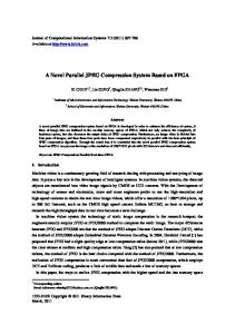
Figure 5. The concept of our view-dependent and multiresolution strategy. (q axis corresponds to quality layer)
2. Send the first layer of the geometry image of the model. 3. Receive the first layer, start to construct the model and then render it.
t
GeometryImage:X3DComposedGeometryNode { SFString [in,out] url [][url or urn] MFInt32 [in] PosMin [0 0 0] (-∞,∞) MFInt32 [in] PosMax [0 0 0] (-∞,∞) MFInt32 [in] NormalMin [0 0 0] (-∞,∞) MFInt32 [in] NormalMax [0 0 0] (-∞,∞) SFInt32 [in] BlockSize [0] [0,∞) }
4. Send the blocks to the client according to the viewing information. 5. When the viewpoint changes, resend the viewing information to the server.
Figure 4. The flowchart of view-dependent and multiresolution transmission.
Figure 5 illustrates the concept of our view-dependent and multiresolution strategy. A JPEG 2000 image (geometry image) is composed of image cubes which correspond to different image blocks and quality layers. During the transmission, the image cubes are selected to transmit depending on user’s requests. After all image cubes are transmitted, the user can get the detailed model with highest quality.
Figure 6. The X3D extension.
From the above advantages, the following discussion shows how the above mentioned points are used in our system:
In our current implementation, each of the x, y, z coordinates and nx, ny, nz normal vectors are represented by one image layer, respectively. In other words, totally we need six image layers. However, traditional JPEG only supports three image layers (i.e., RGB), which forces us to use two JPEG file to represent one 3D model (geometry image). On the other hand, JPEG 2000 supports multi-layer compression, which allows us to easily compress both sets of information into only one image, that means from one JPEG 2000 image (such as shown in Figure 7) we can obtain both of the x, y, z (vertex positions) and nx, ny, nz (normal vectors) information.
Because JPEG 2000 uses wavelet transform to compress the image into multiple quality layers (set to 12). Thus, in the process of transmission, we can decide which layer to be transmitted which allows us to achieve the effect of progressive transferring.
3.6 X3D Extension Our mesh streaming method can be integrated in X3D and serves as a replacement to the node IndexedFaceSet. The prototype is shown in Figure 6.
3.7 The Details of Using JPEG 2000 As previously mentioned, the reason why we chose JPEG 2000 is because geometry images are transmitted over the Internet and need to be compressed. Other reasons are because it provides high flexibilities and has a lossless compression mode. Moreover, it has some other properties that have the advantages for us:
JPEG 2000 supports multiple layer compression, which allows more information to be compressed together in a single image.
JPEG 2000 can be compressed progressively, which allows progressive transmission and decompression.
Arbitrary image block can be retrieved from a JPEG 2000 image, which allows us to achieve view-dependency.
(d)
4.
… X(R)
Y(G)
Z(B)
Result
To show the result, we use a Beethoven model. The information of the model is listed in Table 1. Figure 8 shows the viewdependent result. When the viewing direction changed, the current transmission is stopped and the new viewing part is transmitted. Figure 9 shows the multi-resolution result. With the multilayer JPEG 2000 image, we can see the model being rendered in greater details as more data received by the client as time goes. Table 1. Information of the Beethoven model.
Nx
Figure 7. A JPEG 2000 geometry image (Beethoven) includes the x, y, z coordinates which are encoded as R, G, B information of the image and the normal vectors which is encoded as other images that hided as layers of a JPEG 2000 image
Model
Beethoven
Original File Size (.obj)
322,169 bytes (314 KB)
Image (J2K) File Size
106,982 bytes (105 KB)
Image Resolution
256x256
Block Size
8x8
For achieving the view dependent issue, we adopt the concept of ROI, i.e., we divide the geometry image into several blocks (with size of 8x8), and then the blocks which are close to the user’s viewpoint are selected first. Moreover, when viewpoint changes, we can easily recalculate the new priority block to be transmitted by computing the block indices as the following: Newblockindexi = verticeindexi /(imagesizei / blocksizei ) Newblockindex j = verticeindex j /(imagesize j / blocksize j )
.
When the blocks in the transmission queue are all transmitted, the server will recalculate for the next blocks to be sent.
Figure 9. Multi-resolution result.
Figure 10 shows the result of considering both of the viewdependent and multi-resolution which allows the user to see the model with its quality varies from rough to fine as the server transmits the blocks in sequence. In this figure, we can see the head of the Beethoven at the left was first rendered in greater detail, and the one at the right shows the model is rotated, note that the shoulder has been refined.
Figure 8. View-dependent result.
Figure 11 shows the final result after receiving whole data set from the server. In this figure, the final result looks as good as the original model.
JPEG 2000 image, we can compress the geometry image without data loss (lossless mode) or compress it in high compression rate with a little bit data loss (lossy mode). With JPEG 2000’s support for progressive compression/decompression, we can progressively transmit and render a 3D model to reduce the user waiting time.
Figure 10. View-dependent and multi-resolution result.
Figure 13. The X3D source code of the model shown in Figure 12 (right).
However, even the lossless mode of JPEG 2000 can compress the data without loosing quality; there are still some inherent problems. To convert the 3D model to a geometry image, we have to first cut the model to find the boundary and this actually may cause data loss. Moreover, when using Floater’s method for surface parameterization, there is a tendency to loss the information at sharp regions of a model. Hence, the surface parameterization method should be enhanced to lessen the data loss. Figure 11. The result of receiving whole data.
JPEG 2000 is a currently developing image format. The next step that needs to be accomplished is to allow any client-server system that already supports JPEG 2000 to transmit 3D model with minimum modification. Furthermore, we will also try to integrate our mesh streaming method with some new extensions of JPEG 2000 in the future, such as JPIP (JPEG 2000 Interactive Protocol) [8], which is a new protocol implemented on top of HTTP. Another future work is to further extend this method to a 3D scene. A 3D scene contains more than one 3D model. How to convert these modes into geometry images and still provide view dependency is still a noteworthy problem.
6.
ACKNOWLEDGMENTS
This work is partially supported by the National Science Council of Taiwan under the numbers: NSC92-2218-E-002-056, NSC932622-E-002-033, and NSC94-2622-E-002-024. Figure 12. X3D result.
After incorporating our mesh streaming method into X3D, we can see more extensions and variations. Figure 12 shows the result of combining our mesh streaming method and a X3D library. In this figure, the image at the left has additional material information, and the one at the right has texture information. An example of the original X3D source code is shown in Figure 13.
5.
Conclusion and Future Work
In this paper, we propose a brand new mesh streaming method which used geometry image to store all information of a 3D model or a 3D scene. Since the geometry image is encoded as a
7.
REFERENCES
[1] Chen, B.-Y., and Nishita T. Multiresolution streaming mesh with shape preserving and QoS-like controlling. In ACM Web3D 2002 Conference Proceedings, 2002, 35-42. [2] Floater, M. Parametrization and smooth approximation of surface triangulations. Computer-Aided Geometric Design, 14, 3 (1997), 231–250. [3] Gu, X., Gortler, S. J., and Hoppe, H. Geometry images. ACM Transactions on Graphics (SIGGRAPH 2002 Conference Proceedings), 21, 3 (2002), 355-361. [4] Hoppe, H. Progressive meshes. In ACM SIGGRAPH 1996 Conference Proceedings, 1996, 99-108.
[5] Isenburg, M., and Lindstrom, P. Streaming meshes, In IEEE Visualization 2005 Conference Proceedings, 2005, 231-238.
[8] JPEG 2000 Part 9 Second Final Committee Draft Version 1.0, 2003.
[6] Yang, S., Kim, C.-S., and Kuo, C.-C. J. A progressive viewdependent technique for interactive 3-D mesh transmission. IEEE Transactions on Circuit and System for Video Technology, 14, 11 (2004), 1249-1264.
[9] Virtual Reality Modeling Language (VRML97), ISO/IEC 14772-1:1997, The VRML Consortium, Inc., 1997.
[7] JPEG 2000 Part 1 Final Committee Draft Version 1.0, ISO/IEC FCD15444-1:2000, 2000.
[10] Information technology — Computer graphics and image processing — eXtensible 3D (X3D), ISO/IEC 19775:2004, Web3D Consortium, Inc., 2005.
Figure 14. The result using our view-dependent algorithm. Note that, as the model rotates, the portion closest to the user’s eye will transmit first.
Figure 15. The result using our multi-resolution algorithm. The mesh is refined as more data has received.
Figure 16. The result of combing both view-dependent and multi-resolution algorithms. Note the refinements in the yellow circles.