Available online at www.sciencedirect.com
Procedia Engineering 57 (2013) 1173 – 1182
11th International Conference on Modern Building Materials, Structures and Techniques, MBMST 2013
Applications and Development of Modern Steel Pile Technology Veli-Matti Uotinena,*, Jukka Rantalab b
a Ruukki Construction Oy, Harvialantie 420, 13300 Hämeenlinna, Finland Structural Engineering, Department of Civil Engineering, Tampere University of Technology, Korkeakoulunkatu 10, 33720 Tampere, Finland
Abstract Use of steel piles in general has continuously increased in the Nordic countries as well as in the harbour structures of the Baltics and Western Europe. The main reasons are the innovative, easy-to-handle but rigid and durable pile joints, application of steel material technology and higher steel strength. The importance of the resistance and stiffness of mechanical joints of slender steel piles is accentuated in soft soil conditions. The wide product range and different installation methods enable versatile applications from lightweight to heavily loaded structures in all soil conditions. In harbour structures bending resistance of the pile is often the dimensioning factor. The latest innovations are the highly rigid retaining wall structure, the RD pile wall installed by drilling in all possible soil conditions and steel piles serving as energy piles that exploit renewable ground source energy both for heating and cooling. There has been wide co-operation in Finland between steel pile manufacturers, contractors, designers, manufacturers of piling equipment, researchers and authorities in developing steel pile technology for almost thirty years.
© 2013 2013The TheAuthors. Authors. Published by Elsevier Ltd. access under CC BY-NC-ND license. © Published by Elsevier Ltd. Open Selectionand and peer-review under responsibility of the Gediminas Vilnius Gediminas Technical University. Selection peer-review under responsibility of the Vilnius Technical University Keywords: deep foundations; steel piles; pile joints; bending stiffness; retaining wall structures; high strength steel; renewable energy.
1. Introduction This paper takes a glance at the history of steel piles in the Nordic countries from the 1960’s until present. The emphasis is on recent innovations and practical issues while not forgetting the principles and theories of the structural behaviour of a pile. The importance of the bending stiffness of a pile joint is shown by theoretical calculations and examples of bending stiffness test results are also presented. Development of the steel grades used in steel piles has led to increasingly economical and environmentally friendly and better foundation solutions. High strength steels reduce the amount of steel needed and thereby mitigate the environmental impacts of manufacturing, transporting and installing foundation products. New innovations like energy piles, the drilled pipe pile wall and the RD pile wall widen the application area of steel piles considerably and make it possible to achieve reliable, cost-efficient, technically and schedule-wise safe foundation solutions regardless of geographic location. 2. Use of steel piles from the 1960’s to the 2010’s in the Nordic countries
* Corresponding author. Tel.+358-50-3143-150; fax: +358-20-5925-656. E-mail address:
[email protected]
1877-7058 © 2013 The Authors. Published by Elsevier Ltd. Open access under CC BY-NC-ND license. Selection and peer-review under responsibility of the Vilnius Gediminas Technical University doi:10.1016/j.proeng.2013.04.148
1174
Veli-Matti Uotinen and Jukka Rantala / Procedia Engineering 57 (2013) 1173 – 1182
It is likely that different kinds of steel piles were considered special piles in the 1960’s and 1970’s and that their use was limited to special applications or soil conditions. Steel piles’ share of the total market for piles started to increase gradually in the 1980’s, but substantial growth occurred only in the 1990’s when, for instance in Sweden, their share grew from over 10% to over 30%. In the 2000’s the market share in Sweden stayed at just over 30%. No similar pile statistics are available for Finland and Norway, but the trend and proportional share of steel piles are roughly the same as in Sweden. The main reason for the trend has been the increasing use of steel pipes as piles, especially small diameter piles which are easy to use, rigid and equipped with affordable mechanical pile joints. The development of piling equipment and installation methods has also had a remarkable influence on the trend. Especially the developments in the concentric drilling technique since the mid-1990’s have increased the use of steel pipe piles in hard to penetrate and challenging soil conditions.
Fig. 1. Use of different pile materials in Sweden between 1962–2011. Blue sections of the columns represent steel, gray ones concrete and brown ones timber [1]
One reason for the wider use of medium and large diameter piles (diameter > 400 mm) use has been the increasing use of combi-wall and jetty structures founded on steel piles in harbours and different kinds of bridge foundation applications. Figure 2 presents a typical Finnish small integral bridge with large diameter steel pile foundations. The bridge has only four end-bearing steel pipe piles which connect via reinforced concrete columns to the superstructure. This type of foundation method is very often used in Finland due to the desire to expedite construction and to avoid or minimise excavation and concrete work, which lowers overall foundation costs also in soil conditions where a ground slab foundation could be used.
Fig. 2. Example of an integral bridge with four end-bearing large diameter steel pipe piles. Pile size 711×12.5, pile lengths 18–23 m; the piles are equipped with rock shoes, and maximum characteristic pile load is 4500 kN
Veli-Matti Uotinen and Jukka Rantala / Procedia Engineering 57 (2013) 1173 – 1182
1175
Use of large diameter steel piles started around 1985 in Finland. According to the statistics of the Finnish Transport Agency, 36% of the railways bridges constructed between 1987-2009 have steel pipe pile foundations. Especially since 1992, the so-called bridge-moving technology [2] has increased the use of both driven and drilled large diameter steel piles. The technology enables very fast construction of underpass bridges with minor disturbance to railway traffic in connection with track renovations. The increasing trend of using steel piles is also apparent from Figure 3. It is estimated that there are presently about 600 bridges with steel pile foundations in Finland.
Fig. 3. Bridge statistics. Source: Finnish Road Administration 2011
3. Mechanical pile joints 3.1. General European requirements The main requirements for mechanical pile joints are easy usability in working site conditions as well as sufficient resistance. Joints between load bearing elements must above all have the required capacity in compression, tension and bending [3] while also being capable of maintaining the alignment and position of the pile elements during installation [4]. They shall also safely resist the stresses from handling, driving and actions from the structure and surrounding soil [4]. Therefore, the properties and mechanical resistance of pile joints must be taken into account in pile design and execution. If the pile joint is the weakest part of the pile structure, it limits structural capacity and has a significant impact on the design resistance of the pile. Yet, we know from experience that this fact is often ignored. 3.2. Mechanical pile joints for driven and drilled steel pipe piles The most common pile joint used with driven small diameter steel pipe piles is a conical external splice sleeve based on friction between the joined parts, see Fig. 4. The development of this type of pile joint started in the mid-1980’s and its main principle has remained the same. At the moment, external splice sleeves up to pile diameter d = 219.1 mm are available. This pile joint is easy and fast to use: there is no pile waste because it is possible to start driving the next pile using the section cut part from the previous one.
Fig. 4. External splice sleeve for driven Ruukki RR pile
Conical external threaded splice sleeves up to diameter d = 219.1 mm are available for drilled steel piles, see Fig. 5. These pile joints also are easy to handle and make joining of piles much faster than by welding.
Fig. 5. External threaded splice sleeves for drilled Ruukki RD and RDs piles
1176
Veli-Matti Uotinen and Jukka Rantala / Procedia Engineering 57 (2013) 1173 – 1182
3.3. Requirements for pile joints in the Nordic countries The Nordic countries have set certain more detailed requirements for compression, tension and bending resistance as well as bending stiffness of steel pile joints. The Finnish requirements are presented in the Finnish National Annex to EN 1993-5 (Table 1) [5]. The required values must be met in laboratory tests with driven piles after an impact test, where piles are driven to a certain stress level using a certain number of blows on a test site. Tests with drilled piles are done after the threaded sleeve has been tightened. Table 1. Resistance and stiffness requirements for joints of driven and drilled steel piles. All values are characteristic values. Finnish National Annex to EN 1993-5. The same requirements are also presented in the National Piling Code of Norway (Peleveiledningen 2012) [6] excluding the bending stiffness requirement Compression resistance >Nk,pile
Tension resistance
Bending resistance
Bending stiffness EI (0.3 to 0.8·Mk,pile
>0.15·Nk,pile
>Mk,pile
>0.75·EIp,pile
Compression and bending resistance requirements guarantee the ultimate structural resistance of the pile joint to be as strong as the pile pipe itself. Sufficient tension resistance assures that pile sections can reliably transfer tension forces through a pile joint during installation without the joint loosening or coming apart. 3.4. Impact of bending stiffness of mechanical joints on buckling resistance of steel pipe piles [7] 3.4.1. Background The bending stiffness of mechanical pile joints must be sufficient to prevent significant capacity loss of the pile. The vertical load capacity of slender steel pipe piles is limited by their buckling resistance. Buckling capacity is strongly dependent on surrounding soil conditions and the support the soil provides to the pile. The importance of the bending stiffness of the pile itself increases as the elastic modulus of the soil decreases. Usually a pile section with any kind of mechanical joint element is less rigid than a continuous pile section, with the possible exception of a good weld joint. However, the bending stiffness of joints does not necessarily have to be as rigid as the stiffness of the pile pipe itself. A short section of a pile (here a joint) of weaker bending resistance has only a limited impact on the total bending resistance of the pile shaft. From the practical point of view, a pile always has initial deflection after installation. The magnitude of the initial deflection is strongly dependent on soil conditions. For example, in stony soil conditions driven piles tend to bend more than in homogenous cohesive soils like clay and silt. With driven piles, the impact during driving is always more or less eccentric causing moment stresses to pile which may increase deflection especially with slender piles. If the pile joint is loose and allows angular deformation, or has significantly lower bending stiffness than the pile shaft, it can be assumed that the risk of an unacceptable level of initial deflection accumulating increases. In the Nordic countries it is always assumed in design that a pile with a joint or joints has a larger initial deflection than a pile without joints, even though the pile joints can be considered rigid and stiff due to the high requirements presented in Table 1. Larger initial deflection decreases buckling capacity. 3.4.2. Bending stiffness of steel pipe piles with mechanical joints Here we examine a pile with two separate sections and a total length of l = a (m). The bending resistance of the continuous pile pipe is EIpile (kNm2). The joint between the two pile sections is assumed to be a simply point-like joint with a rotational stiffness of K (kNm/rad). If constant bending moment (M) is applied to the pile section including a joint, the total deflection of this section is a combination of the deflection of a continuous pile section of equal length Eq. (1) and the deflection caused by the rotation of the joint Eq. (2).
v pile =
M ⋅ a2 8 ⋅ EI pile
(1)
M ⋅a 4⋅K
(2)
v jo int =
The combined bending stiffness of the pile section (1) with a joint (EIshaft) can now be determined from
1177
Veli-Matti Uotinen and Jukka Rantala / Procedia Engineering 57 (2013) 1173 – 1182
Eq. (3) and Eq. (4).
M ⋅ a2 M ⋅ a2 M ⋅a = + 8 ⋅ EI shaft 8 ⋅ EI pile 4 ⋅ K
EI shaft =
(3)
a a 2 + EI pile K
(4)
In the following examples the impact of the rotational stiffness of the joint (K) on the total stiffness of the pile section (EIshaft) is examined with three pile sizes, RR140/10 (steel pile diameter d = 139.7 mm and wall thickness t = 10.0 mm), RR170/12.5 (d = 168.3 mm, t = 12.5 mm) and RR220/12.5 (d = 219.1 mm, t = 12.5 mm). Later the buckling resistance of the pile sections of varying joint stiffness will be determined by 3D FE analysis using the ANSYS program. The results will be compared with the resistance of the solid continuous pile section. The pile sections were modelled as 3D surface elements. The yield strength of the pile material was fy = 440 MPa. The joint itself was modelled with transitional constraints and elastic rotational springs so that no material parameters were required. The supporting soil was modelled as non-linear springs. Subgrade reaction value k was calculated according to Eq. (5) and ultimate earth pressure pm according to Eq. (6).
k = A ⋅ cuk / D
(5)
pm = B ⋅ cuk
(6)
The modelled pile had an initial radius of curvature and an initial eccentricity, in this case δecc = a/200. The geometric variables as well as the material parameters applied in each analysis are presented in Table 2. The length of the analysed pile (a) was longer than the effective length of the pile in the given soil conditions. The joint was placed at the mid-section of the pile, where the eccentricity and thus the bending moment were highest. Table 2. Initial geometrical and material parameters of the performed analysis Calculation Pile d/t/cuk/
a (m)
δecc (mm) = a/200
R (m)
fy (MPa)
cuk (kPa)
A (-)
B (-)
Pm (kPa)
RR140/10/5/
6,0
32,2
136
440
5
50
9
45
RR140/10/10/
5,5
27,4
136
440
10
50
9
90
RR170/12.5/10/
4,7
20,7
136
440
20
50
9
180
RR220/12.5/10/
6,0
30,1
150
440
10
50
9
90
3.4.3. Results of the FE analysis The initial stiffness values of the analysed RR140/10 piles were calculated according to Eq (4). The bending stiffness of the solid pile pipe was EIpile = 1810 kNm2. The rotational stiffness of the joint was chosen so that the bending stiffness of the analysed pile section including the joint (EIshaft) was either 50%, 60%, 70% or 80% of the solid reference pile. The analysis was performed with two different values (cuk = 5 kPa and 10 kPa). Table 3 presents the results of the FE analysis for the RR140/10 joints. Pshaft denotes the buckling resistance of the pile shaft including a joint of varying rotational stiffness. K denotes the applied rotational stiffness of the joint (kNm/rad) and EIshaft/EIpile indicates the ratio of the bending stiffness of the pile section with a joint (EIshaft) to the solid reference section (EIpile). According to FE modelling, the buckling capacity of the solid reference pile with cuk = 5 kPa was Pu = 825 kN and with cuk = 10 kPa These were used as a reference in determining the relative buckling capacity (Pshaft/Pu) in Table 3. Similar calculations were also done with regard to pile sizes RR170/12.5 and RR220/12.5. Figure 6 presents all the calculation results. In general, the significance of variation in any individual property on the overall bearing capacity of a structure is considered minor, if the impact of the variation is less than 5%. Here, the general assumption is made that the vertical load capacity of a pile including joints should be at least 95% of the buckling capacity of a continuous reference pile. It ensures
1178
Veli-Matti Uotinen and Jukka Rantala / Procedia Engineering 57 (2013) 1173 – 1182
that the overall variation in the vertical load capacity of the pile does not exceed acceptable limits. The bending stiffness of a jointed pile must be adequate for this requirement to be satisfied. Table 3. Results of the analysis of the RR140/10 joints cuk
K
EIshaft/EIpile
Pshaft
Pu
Pshaft/Pu
(kPa)
(kNm/rad)
(%)
(kN)
(kN)
(%)
140/10/5/60
5
994
60
750
825
90,0
140/10/5/70
5
1547
70
789
825
95,6
140/10/5/80
5
2652
80
813
825
98,5
140/10/10/50
10
663
50
984
1160
88,9
140/10/10/60
10
994
60
1006
1160
90,9
140/10/10/70
10
1547
70
1050
1160
94,9
140/10/10/80
10
2652
80
1076
1160
97,3
Analysis code
Fig. 6. Comparison of the calculated shaft stiffness/load capacity ratios of different pile sizes
According to these calculations, the steel pipe piles consisting of separate pile sections and joint elements should have a combined bending stiffness of EIshaft ≥ 0.75 × EIpile, where EIpile is the stiffness of a continuous reference pile. 3.5. An example of laboratory test results Figure 7 presents the arrangements of the bending test and Figure 8 presents the bending test results for RR170/12.5 piles [8].
(a)
(b) Fig. 8. Bending test (a) bending test on RR140/10 pile; (b) results for RR170/12.5 pile, blue curves represent the pile without a joint [8]
The test results show that a pile with a joint has higher bending resistance and at least as high bending stiffness as a pile without a joint, which means that the requirements are satisfied.
Veli-Matti Uotinen and Jukka Rantala / Procedia Engineering 57 (2013) 1173 – 1182
1179
3.6. An example of the analysis of a threaded male-female pile joint Threaded male-female pile joints are in some cases used with drilled piles. According to analysis [9], the bending moment capacity of the male-female splices tends to be significantly lower than the capacity of the pile pipe itself. According to FE calculations, effective bending resistance was only 68–75% of the capacity of the pile pipe. The bending stiffness of a –male-female jointed pile is only 36–56 % of the pile shaft’s, which further decreases the effective vertical load capacity of the pile as the buckling resistance of the pile decreases. Figure 9 presents an example of the FE calculations [9]. Moreover, the actual compression resistance of the male-female splice is often significantly lower than that of the pile pipe itself. Tests performed on RD140/10 piles showed [10] that the axial capacity of a pile may decrease 25% due to a single weak male-female splice along its shaft. In summary, the mechanical properties of a pile joint have a significant impact on the design resistance of pile, and if such weak pile joints are used, the reduced capacity should be taken into account in design to avoid overloading and failure of the pile.
Fig. 9. Example of an analysis of a threaded male-female joint of an RD220/12.5 pile. The residual wall thickness of both the male and female sections at the thread base was approx. 5 mm. Load-displacement curve in bending
3.7. Manufacture of pile joints Based on long experience and numerous laboratory tests, steel pipe manufacturing tolerances have to be clearly stricter than those presented in execution standard EN10219-2 to satisfy high resistance requirements while also ensuring the usability of pile joints at working site. 4. High strength steels 4.1. General Traditionally steel grade S355J2H, or the former St52 or other steel grades with a yield strength of 355 MPa, have been widely used in steel piles. Special steel grades S440J2H and S550J2H were developed in the Nordic countries for piles and taken into general use in 2003–2004 and 2007–2008, respectively. Common features of these higher strength steels in addition to high yield strength are their good impact toughness, good weldability and high fatigue strength which are important for mechanical pile joints. These steel grades are not included in EN10219-1 but are included in European Technical Approval ETA-12/0526 [11]. 4.2. Benefits of high strength steels in foundation structures Structural bearing resistance in compression and moment resistance increase linearly as yield strength increases. For example, resistance increases 55% from S355J2H to S550J2H. That can be taken advantage of in two ways with endbearing piles: more bearing capacity per pile or fewer piles per project, or the pile size can be decreased while achieving the same bearing capacity which results in less disturbance in the form of vibrations and soil displacements to the environment. In the case of friction piles, like shaft grouted steel piles, the internal or structural capacity of pile can be achieved with less steel material. Combi-wall structures, where steel pipe piles act as king piles and intermediate sheet piles as secondary elements, are often used in harbour projects as wharf walls. By optimising the pile diameter, wall thickness and steel grade of king piles,
1180
Veli-Matti Uotinen and Jukka Rantala / Procedia Engineering 57 (2013) 1173 – 1182
significant savings in steel material and costs can be achieved with high strength steels. As shown in Figure 10, if S550J2H is chosen instead of S355J2H, the material savings on a theoretical 500 m long wharf wall can be 280 tonnes if the intermediate sheet piles, diameter of the king pile, corrosion allowance and required plastic bending moment resistance for the retaining wall remain the same. D=1016 mm, t=16mm L=10m primary element S355J2H Double PU12 secondary elements Corrosion allowance 3.5mm front and 1.2 mm back Plastic bending moment resistance 2.011 MNm/m Length of wall 500 m
Fig. 10. Example of combi-wall structure optimisation with high strength steels
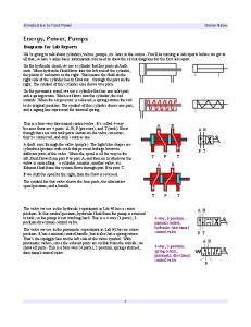
In addition to reduced costs, the environmental impact of manufacturing and processing the steel material and pile products, transportation and installation of piles, is significantly reduced by the use of high strength steels. 5. The RD pile wall – a new way to build a retaining wall in challenging soil conditions 5.1. Principle and main benefits of the method Ruukki RD pile walls can be used in extremely demanding soil conditions where the installation of traditional retaining walls is challenging. The RD pile wall is a combination of Ruukki drilled steel pipe piles and interlocking sections, see Fig. 11. Individual RD piles are connected to each other with interlocks welded to the piles on the automated welding line at the workshop. The matching dimensions of the drilling system and interlocking sections allow the installation of RD piles through stones and boulders and even into the bedrock, if necessary, in a single operation. Installation is done by a downthe-hole hammer (DTH) using the centric drilling system and oversized ring bits or a drilling system consisting of a pilot bit and reamer wings. The RD pile wall can be implemented as a watertight construction using interlock sealants. Watertightness of the joint between the lower end of the wall and the underlying bedrock can be ensured by grouting through the injection channels located in the wider interlock section.
Fig. 11. Principle of joining pipe piles, interlocks and ring bits. 3rd pile on the right is being installed
The installed wall can function both as a temporary and a permanent structure. A clear benefit is its ability to take both heavy vertical and horizontal loads, if necessary. The solution allows installing a retaining wall in bedrock and thus providing good lateral support for the lower end of the wall. Available procedures and components allow easy control of the water tightness of the wall according to soil conditions and structural requirements. The installation speed is almost independent of soil conditions, which means that installation time can be estimated quite accurately. The installation speed can be many times faster than that of a secant pile wall. Tests have been conducted with several pile dimensions, and optimisation of interlocks and drilling systems has been done in co-operation with both suppliers and contractors. Moreover, several demanding projects using the wall have already been successfully completed in Scandinavia.
1181
Veli-Matti Uotinen and Jukka Rantala / Procedia Engineering 57 (2013) 1173 – 1182
5.2. Reference projects More than 2200 piles and 25,000 m of drilled steel pipe piles have been successfully installed in the form of RD pile walls in different projects and test installations since 2009 in the Nordic countries. Table 4 presents the completed projects excluding test installations. Table 4. RD pile wall projects Project
Year
Purpose or type of structure
Pile size
Pile lengths
Trondheim E6, Norway [12,13]
2010–2011
Watertight retaining wall for tunnel construction
RD610/10
10–32 m
Motala, underpass bridge, Sweden
2010
Temporary retaining wall for excavation for bridge
RD406/12.5
8–12 m
Kiruna, bridge, Sweden
2010
Bridge foundation piles
RD508/14.2
10–15 m
Kalasatama Centre, Helsinki, Finland
2011–2012
Watertight permanent retaining walls for access tunnels and underground spaces
RD610/12.5
3–14 m
Western metroline, Katajaharju shaft, Helsinki, Finland
2011–2012
Retaining wall for excavation of ventilation shaft
RD406/12.5
16–20 m
Western metroline, Koivusaari metro station, Helsinki, Finland (see Fig. 12)
2012
Watertight retaining wall for excavation for entrances of metro station
RD610/12.5
6–12 m
Central parking facility, Tapiola, Espoo, Finland
2012–
Retaining wall for excavation of shaft
RD220/10
8–9 m
Fredriksdahl bussdepå, Stockholm, Sweden
2012–
Temporary retaining wall for excavation
RD406/12.5
10–15 m
Strömkajen, Stockholm, Sweden
2012–
Temporary retaining wall for excavation
RD220/10
5–9 m
Fig. 12. RD pile wall project for Western metroline, Koivusaari metro station. Situation after installation of RD pile wall and first anchoring level, July 2012
6. Other applications and outlook for the future 6.1. Energy steel piles Steel piles are easy to use as energy piles as they are hollow. Energy piles are installed in steel pipe foundation piles to collect heat. Geothermal energy and energy stored in the ground during summer is utilised for heating, and low soil temperature is utilised in cooling. Both normal driven and drilled steel pipe piles are suitable for energy piles without any major modifications to pile components or pile installation methods. Literature studies, in situ tests (thermal response tests), laboratory tests and modellings of the whole heating/cooling system of a building, including energy piles, have been done to evaluate the applicability of the solution to Nordic soil conditions and climate. According to the studies and tests, the overall potential of an energy pile system depends most on soil conditions, the number and length of the piles used and the design of the building. An efficient energy pile system requires that the building has a balanced cooling/heating ratio and the soil accumulates heat in summer. It is recommended that in summertime at least 70% of the energy used for heating during the heating season is pumped back into the soil [14]. According to geothermal energy production simulations and cost-calculations based on the current price level of energy and other heating/cooling systems, pile length should be at least 10–15 metres and the piles spaced about 4 metres apart to produce and economical heating/cooling system.
1182
Veli-Matti Uotinen and Jukka Rantala / Procedia Engineering 57 (2013) 1173 – 1182
The first energy pile project in Finland is underway in Jyväskylä. A 6-storey office building in the city has 38 energy piles constituting 15% of its foundation piles. It is estimated that the energy pile system will provide almost 50% of the total heating energy and about 38% of the cooling energy required by the building, and the investment payback period has been calculated to be 9–10 years. Soil investigations have included determination of the thermal conductivity of soil and measured values will be compared to literature values. Soil temperature will also be monitored during the service life of the energy piles. Figure 13 illustrates the energy pile configuration in Jyväskylä [15].
Fig. 13. Energy pile system with soil temperature monitoring points and energy pile configuration of one column footing
6.2. Outlook for the future Demand for greener energy, lower energy consumption, lower emissions and promotion of renewable energy sources create potential for increased use of both high strength steel piles and energy piles in the future. The continued concentration of building activities in cramped areas of city centres opens possibilities for utilising innovative deep foundation solutions like RD pile walls. Increasing costs and lack of building land will lead to more underground construction and facilities. An efficient, fast and reliable splicing technique enables cost-effective underpinning of existing buildings in restricted headroom with steel micropiles. Demand for prefabrication of building products and solutions, as well as demand for quicker and safer installation and construction processes on site, will create and maintain the need for new modifications, solutions and innovations within steel pile technology also in the future.
References [1] Pålkommissionen, Commission on pile research, Pålstatistik för Sverige 2011, informationen 2012:1, Linköping 2012 [2] Kataja, J., 2009. Construction of railway bridges under traffic, Presentation at Educational Course on Railway Track Technology, NBIU 2009 Ellivuori, Finland [3] The European standard 14199:2005. Execution of special geotechnical works. Micropiles. Chapter 7.5.3. [4] The European standard 12699:2000. Execution of special geotechnical works. Displacement piles. Chapter 7.8.4. [5] National annex to standard SFS-EN 1993:5 Eurocode 3: Design of steel structures. Part 5: Piling. [6] Norsk Geoteknisk Forening, Den Norske Pelekomite, Peleveiledningen 2012 (National desing and installation guide of piling in Norway). [7] Rantala, J., 2011. Impact of bending stiffness of mechanical joints on buckling resistance of steel pipe piles, Internal report, Ruukki Construction Oy F [8] KTH (Kunglica Tekniska Högskola), 2012. Testing of RR170/12.5 with friction splices, Internal report, Ruukki Construction, Stockholm. [9] Rantala,J., 2012. Mechanical properties of threaded m/f -splices for RD –piles, Internal report, Ruukki Construction Oy. [10] Eronen, S., 2011. Drilled steel pipe piles in underpinning and bridge foundations, Publication 52, Tampere University of Technology, Laboratory of Foundation and Earth Structures, Tampere. [11] European Technical Approval ETA-12/0526, 2012. RR, RRs, RD and RDs piles, Steel pipe piles made of structural steel, Ruukki Construction Oy. [12] Ihler, H., 2012. “RD-pile wall - A new retaining wall for demanding soil conditions”, Proceedings of the 16th Nordic Geotechnical Meeting, Copenhagen, pp. 599-607. [13] Beitnes, A., 2011. “E6 Trondheim – Stjørdal, section Trondheim – cut and cover tunnel”, Special challenges calling for special measures, Proceedings of the 49th Fjellsprengningsdagen, Bergmekanikkdagen, Geoteknikkdagen, 2011, pp. no. 22, 10 p. [14] Fromentin, A., Pahud, D., 1997. Recommendations pour la realisation d’installations avec pieux exchangeurs. Rapport final, Ecole Polytecnhique Federala Lausanne, LASEN, 1015, Lausanne, witzerland [15] Uotinen, V-M., 2012. “Energy piles – ground energy system integrated to the steel foundation piles”, Proceedings of the 16th Nordic Geotechnical Meeting, pp. 837-844.