ZOPT2202
Digital UVA / UVB Energy Sensor
Datasheet
Description The ZOPT2202 Sensor integrates two types of ultra-violet optical sensors: one that is primarily sensitive in the UVA spectral range and one that is sensitive in the UVB spectral range. The device is connected via an I²C interface to a microcontroller. Other I²C or SMBus devices can be connected to the same interface. The device has a programmable interrupt with hysteresis to respond to events and reduce the microcontroller tasks. A major application of the device is in smart phones or other mobile devices to enable UVA and UVB energy level measurements in support of diverse health care applications or contextual awareness algorithms.
Physical Characteristics
Features
Very high sensitivity for UVA and UVB energy levels Superior visible light and infrared energy suppression Very stable spectral response over angle of light incidence Large dynamic range Excellent temperature compensation Lowest conversion repeat noise Parallel operation of UVA and UVB sensor I²C interface capable of standard mode (100kHz) or fast mode (400kHz) communication; 1.8V logic compatible Programmable interrupt function for UVA or UVB sensor with upper and lower thresholds
Wide operation temperature: - 40°C to +90°C Wide supply voltage: 1.7V to 3.6V Minimum active current at maximum duty cycle: — Single channel: 110µA typical — Dual channel: 130µA typical Note: Average current is proportionally lower with lower measurement rates. Low standby current: 1µA typical Packages: — LGA6 (2.0 2.2 0.7 mm) — TSV (1.1 1.2 0.26 mm)
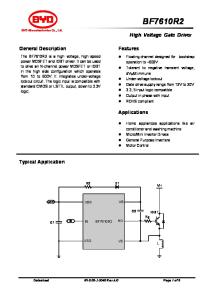
ZOPT2202 Application Circuit VDD1 VDD1: 1.7 to 3.6 V VDD2: 1.7 to 3.6 V
Sensor Features
VDD2
VDD2 VDD
UVA/UVB sensor in a matrix array arrangement Configurable output resolution: 13 to 20 bits
VDD
ZOPT2202
Configurable analog gain: 1 to 18 Linear output code Fluorescent light flicker immunity
µC
SCL SDA INT
SCL SDA INT
GND
GND
© 2016 Integrated Device Technology, Inc
1
September 21, 2016
ZOPT2202 Datasheet
ZOPT2202 Block Diagram
VDD 1.7 to 3.6V Reference
Regulator
Main State Machine
NVM
ADC UVA
ADC UVB Sensor Control
INT
Interrupt Control
ADC UVB2 Register File
SDA ADC UV_COMP
I²C SCL
ADC COMP
Applications Cellular phones Notebooks Consumer devices
Bandgap
Power-On-Reset
Oscillator
GND
= Analog Block
= Digital Block
Ordering Information Product Sales Code
Description
Package
ZOPT2202AC5R
ZOPT2202 LGA6 – Temperature range: -40 to +90°C
Reel
ZOPT2202AC9R
ZOPT2202 TSV – Temperature range: -40 to +90°C
Reel
ZOPT2202KIT V1.0
ZOPT2202 Evaluation Kit, including ZOPT Control Board, mini-USB cable, and 1 ZOPT2202 sample mounted on the LGA6 Sensor Board; kit software is available for free download – see the ZOPT Evaluation Kit Quick Start-up Guide included in the kit for instructions.
Corporate Headquarters
Sales
Tech Support
6024 Silver Creek Valley Road San Jose, CA 95138 www.IDT.com
1-800-345-7015 or 408-284-8200 Fax: 408-284-2775 www.IDT.com/go/sales
www.IDT.com/go/support
DISCLAIMER Integrated Device Technology, Inc. (IDT) reserves the right to modify the products and/or specifications described herein at any time, without notice, at IDT's sole discretion. Performance specifications and operating parameters of the described products are determined in an independent state and are not guarante ed to perform the same way when installed in customer products. The information contained herein is provided without representation or warranty of any kind, whether express or implied, includin g, but not limited to, the suitability of IDT's products for any particular purpose, an implied warranty of merchantability, or non-infringement of the intellectual property rights of others. This document is presented only as a guide and does not convey an y license under intellectual property rights of IDT or any third parties. IDT's products are not intended for use in applications involving extreme environmental conditions or in life support systems or similar devices where the failure or malfunction of an IDT product can be reasonably expected to significantly affect the health or safety of users. Anyone using an IDT product in such a manner does so at their own risk, absent an express, written agreeme nt by IDT. Integrated Device Technology, IDT and the IDT logo are trademarks or registered trademarks of IDT and its subsidiaries in the United States and other countries. Other trademarks used herein are the property of IDT or their respective third party owners. For datasheet type definitions and a glossary of common terms, visit www.idt.com/go/glossary. All contents of this document are copyright of Integrated Device Technology, Inc. All rights reserved.
© 2016 Integrated Device Technology, Inc
2
September 21, 2016
ZOPT2202 Datasheet
Contents 1.
Characteristics ..............................................................................................................................................................................................6 1.1 Absolute Maximum Ratings .................................................................................................................................................................6 1.2 Operating Conditions ...........................................................................................................................................................................6 1.3 Electrical and Optical Parameters .......................................................................................................................................................7
2.
Typical Device Parameters ...........................................................................................................................................................................9
3.
Detailed Description ...................................................................................................................................................................................12 3.1 Block Diagram of ZOPT2202 .............................................................................................................................................................12 3.2 Application Circuit ..............................................................................................................................................................................13 3.3 Pin Description ..................................................................................................................................................................................14 3.4 Device Operation Modes ...................................................................................................................................................................15 3.5 Conversion Control State Machine ....................................................................................................................................................17 3.5.1
Start Up after Power-On or Software Reset .......................................................................................................................17
3.6 UV Sensor Sensitivity Configuration ..................................................................................................................................................18 3.6.1
Analog Gain Modes, Resolution, and Measurement Time .................................................................................................18
3.7 Interrupt Features ..............................................................................................................................................................................19 3.8 I²C Interface .......................................................................................................................................................................................20 3.8.1
I²C Address Decoding ........................................................................................................................................................20
3.8.2
I²C Register Read ...............................................................................................................................................................20
3.8.3
Register Write .....................................................................................................................................................................21
3.8.4
I²C Interface—Bus Timing ..................................................................................................................................................22
3.9 Summary of Internal Registers ..........................................................................................................................................................23 3.10 Detailed Description of Registers ......................................................................................................................................................24 3.10.1
MAIN_CTRL .......................................................................................................................................................................24
3.10.2
LS_MEAS_RATE ...............................................................................................................................................................25
3.10.3
LS_GAIN ............................................................................................................................................................................26
3.10.4
PART_ID ............................................................................................................................................................................27
3.10.5
MAIN_STATUS ..................................................................................................................................................................27
3.10.6
UVB2_DATA.......................................................................................................................................................................28
3.10.7
UVA_DATA.........................................................................................................................................................................29
3.10.8
UVB_DATA.........................................................................................................................................................................30
3.10.9
UV_COMP_DATA ..............................................................................................................................................................31
3.10.10 COMP_DATA .....................................................................................................................................................................32 3.10.11 INT_CFG ............................................................................................................................................................................33 3.10.12 INT_PST .............................................................................................................................................................................33 3.10.13 LS_THRES_UP ..................................................................................................................................................................34 3.10.14 LS_THRES_LOW ...............................................................................................................................................................34 3.10.15 LS_THRES_VAR................................................................................................................................................................35 3.10.16 DEVICE_CONFIG ..............................................................................................................................................................35
© 2016 Integrated Device Technology, Inc
3
September 21, 2016
ZOPT2202 Datasheet 4.
Packages ....................................................................................................................................................................................................36 4.1 LGA6 Package (2.0 2.2 0.7 mm) ................................................................................................................................................36 4.1.1
Mechanical Dimensions......................................................................................................................................................36
4.1.2
Pin Assignment (Top View) ................................................................................................................................................36
4.1.3
Reflow Profile .....................................................................................................................................................................37
4.1.4
LGA Tape Packaging Information ......................................................................................................................................38
4.2 TSV Package (1.1 1.2 0.26 mm) ................................................................................................................................................39 4.2.1
Mechanical Dimensions......................................................................................................................................................39
5.
Part Order Information ................................................................................................................................................................................40
6.
Glossary .....................................................................................................................................................................................................40
7.
Document Revision History ........................................................................................................................................................................41
List of Figures Figure 2.1
UVAS Spectral Response – Linear ...................................................................................................................................................9
Figure 2.2
UVAS Spectral Response – Logarithmic ..........................................................................................................................................9
Figure 2.3
UVBS Spectral Response – Linear ...................................................................................................................................................9
Figure 2.4
UVBS Spectral Response – Logarithmic ..........................................................................................................................................9
Figure 2.5
UVAS Spectral Response vs. AOI ..................................................................................................................................................10
Figure 2.6
UVBS Spectral Response vs. AOI ..................................................................................................................................................10
Figure 2.7
UVAS Field of View (375nm LED) ..................................................................................................................................................10
Figure 2.8
UVAS Field of View (Polar) (375nm LED) ......................................................................................................................................10
Figure 2.9
UVBS Field of View (310nm LED) ..................................................................................................................................................10
Figure 2.10 UVBS Field of View (Polar) (310nm LED) ......................................................................................................................................10 Figure 2.11 Conversion Repeat Noise ...............................................................................................................................................................11 Figure 2.12 Active Current vs. Supply Voltage ..................................................................................................................................................11 Figure 2.13 Normalized Active Current vs. Temperature ...................................................................................................................................11 Figure 2.14 Standby Current vs. Temperature ...................................................................................................................................................11 Figure 3.1
Simplified ZOPT2202 Block Diagram .............................................................................................................................................12
Figure 3.2
Typical Application Circuit ...............................................................................................................................................................13
Figure 3.3
Main State Machine ........................................................................................................................................................................17
Figure 3.4
Interrupt Unit ...................................................................................................................................................................................19
Figure 3.5
I²C Register Read ...........................................................................................................................................................................21
Figure 3.6
I²C Register Write ...........................................................................................................................................................................21
Figure 3.7
Bus Timing ......................................................................................................................................................................................22
© 2016 Integrated Device Technology, Inc
4
September 21, 2016
ZOPT2202 Datasheet
List of Tables Table 3.1
LGA Pin Description........................................................................................................................................................................14
Table 3.2
TSV Pin Description ........................................................................................................................................................................14
Table 3.3
Mode Descriptions ..........................................................................................................................................................................15
Table 3.4
Channel Activation vs. Operation Mode ..........................................................................................................................................16
Table 3.5
UVAS Sensitivities ..........................................................................................................................................................................18
Table 3.6
UVBS Sensitivities ..........................................................................................................................................................................18
Table 3.7
Supported I²C Clock Frequencies ...................................................................................................................................................20
Table 3.8
I²C Address .....................................................................................................................................................................................20
Table 3.9
Bus Timing Characteristic ...............................................................................................................................................................22
Table 3.10 Register Overview...........................................................................................................................................................................23 Table 4.1
Reflow Profile Specifications...........................................................................................................................................................37
© 2016 Integrated Device Technology, Inc
5
September 21, 2016
ZOPT2202 Datasheet
1. Characteristics 1.1
Absolute Maximum Ratings
The absolute maximum ratings are stress ratings only. The device might not function or be operable above the recommended operating conditions given in section 1.2. Stresses exceeding the absolute maximum ratings might damage the device. In addition, extended exposure to stresses above the recommended operating conditions might affect device reliability. IDT does not recommend designing to the “Absolute Maximum Ratings.” Parameter
Symbol
Maximum input supply voltage (VDD pin)
Conditions
Min.
VDD-GND
Maximum voltage on SCL, SDA and INT pins Maximum operating temperature range Storage temperature Maximum input current into any pin except supply pins (latch-up) Electrostatic Discharge Protection[a]
Max.
Units
4.0
V
VI2C
-0.5
4.0
V
TAMB_MAX
-40
90
°C
TSTOR
-45
95
°C
IIN
-100
100
mA
Human Body Model, JESD22-A114
VHBM
2000
V
[a] HBM: C = 100pF charged to VHBM with resistor R = 1.5k in series; valid for all pins.
1.2
Operating Conditions Parameter
Symbol
Conditions
Min.
Typ.
Max.
Units
Voltage supply on VDD pin
VDD
1.7
3.6
V
Ambient operating temperature range
TAMB
-40
90
°C
© 2016 Integrated Device Technology, Inc
6
September 21, 2016
ZOPT2202 Datasheet
1.3
Electrical and Optical Parameters
VDD = 2.8V, TAMB= -40°C to +90°C, unless otherwise noted. Note: See important table notes at the end of the table.
Parameter
Symbol
Conditions
Min.
Typ.
Max.
Unit
1.00
1.34
1.60
V
Power On Reset DC power-on reset level
PORLH PORHL
Slow variation of VDD
Current Consumption UVAB_S Mode[a]
IUVA
Maximum duty cycle, VDD = 2.8V
110
µA
UVB_ONLY Mode [a]
IUVB
Maximum duty cycle, VDD = 2.8V
100
µA
UVAB_Raw Mode [a]
IUVA+B
Maximum duty cycle, VDD = 2.8V
130
µA
Standby Mode
ISBY
ZOPT2202 in Standby Mode, no active I²C communication
1
2
µA
I2C Interface I²C signal input high
VI2Chigh
1.5
VDD
V
I²C signal input low
VI2Clow
0
0.4
V
UVAS Characteristics Spectral response
See Figure 2.1 and Figure 2.2.
Sensitivity at gain 1
G1
Sensitivity at gain 3
G3
Sensitivity at gain 6 [b]
G6
Sensitivity at gain 9 [b]
G9
Sensitivity at gain 18 [b]
G18
Calibrated error at gain 18
© 2016 Integrated Device Technology, Inc
0.106
Specifications apply to the 20-bit resolution setting. Specifications change with resolution setting as given in Table 3.5.
0.035 0.018 0.012 0.006
Calibration done with UVA LED, 360nm, TAMB = +25°C
7
10
%
September 21, 2016
ZOPT2202 Datasheet
Parameter
Symbol
Conditions
Min.
Typ.
Max.
Unit
UVBS Characteristics Spectral response
See Figure 2.3 and Figure 2.4.
Sensitivity at gain 1
G1
Sensitivity at gain 3
G3
Sensitivity at gain 6 [b]
G6
Sensitivity at gain 9 [b]
G9
Sensitivity at gain 18 [b]
G18
0.36 0.12
Specifications apply to 20-bit resolution setting. Specifications change with resolution setting as given in Table 3.6
0.06 0.04 0.02
Calibration done with UVB LED, 310nm, TAMB = +25°C
Calibrated error at gain 18
10
%
18
20
Bit
5
20
Count
UVA / UVB Sensor Characteristics UVA / UVB sensor output resolution
UVA / UVB sensor dark level count
UVSRES
Programmable for 13, 16, 17, 18, 19, 20 Bit
UVSDARK
No illumination 20-bit resolution Gain range x18 TAMB = -40 to +60°C
13
Conversion Timing Minimum integration time [c] Maximum integration time [c] Wake-up time from Standby Mode Measurement repeat rate [c]
tINTmin1
3.125
ms
tINTmin2
With 50/60 Hz rejection
50
ms
tINTmax
With 50/60 Hz rejection
400
ms
From Standby to Active Mode (measurement can start)
500
µs
tWAKE-STB
Programmable
Timing accuracy [d]
25
2000
ms
-25
+25
%
[a] Maximum duty cycle is selected with a 100ms measurement time and 100ms repeat rate. [b] Values valid up to 60°C. [c] Typical timing accuracy applied. [d] All specifications related to timing can vary by this value; for example, a repeat rate of 50ms could vary up to 62.5ms.
© 2016 Integrated Device Technology, Inc
8
September 21, 2016
ZOPT2202 Datasheet
2. Typical Device Parameters (VDD = 2.8V; ZOPT2202 configuration: 20-bit resolution and gain range x18; other settings at default unless otherwise noted.) Figure 2.1 UVAS Spectral Response – Linear
Figure 2.2 UVAS Spectral Response – Logarithmic
120%
1.E+00
250
450
550
650
750
850
950
1050
1.E-01
80%
normalized responsivity
normalized responsivity
100%
350
60%
40%
1.E-02
1.E-03
1.E-04
20% 1.E-05
Unverifiable measurement tool limit reached
0% 250
350
450
550
650 750 wavelength (nm)
850
950
1050
1.E-06
Figure 2.3 UVBS Spectral Response – Linear
wavelength (nm)
Figure 2.4 UVBS Spectral Response – Logarithmic
120%
1.E+00
250 100%
350
450
550
650
750
850
950
1050
1.E-01
80%
normalized responsivity
normalized responsivity
data;
60%
40%
1.E-02
1.E-03
1.E-04
Unverifiable measurement tool limit reached
data;
20% 1.E-05 0% 250
350
450
550
650 750 wavelength (nm)
© 2016 Integrated Device Technology, Inc
850
950
1050
1.E-06
9
wavelength (nm)
September 21, 2016
ZOPT2202 Datasheet
Figure 2.5 UVAS Spectral Response vs. AOI
Figure 2.6 UVBS Spectral Response vs. AOI
1
1
0.9
0.9 UVB -60deg
0.8
0.8
UVA -60deg
UVB -50deg
0.7
normalized responsivity
normalized responsivity
UVA -50deg UVA -40deg
UVA -30deg
0.6
UVA -20deg
0.5
UVA -10deg UVA 0deg
0.4
UVA 10deg
UVA 20deg
0.3
UVB -40deg
0.7
UVB -30deg UVB -20deg
0.6
UVB -10deg
0.5
UVB 0deg
UVB 10deg
0.4
UVB 20deg
0.3
UVB 30deg
UVA 30deg
0.2
UVB 40deg
0.2
UVA 40deg UVA 50deg
0.1
UVB 50deg
UVB 60deg
0.1
UVA 60deg
0
0
300
325
350
375 wavelength (nm)
400
425
450
Figure 2.7 UVAS Field of View (375nm LED)
250
275
300
350
375
400
Figure 2.8 UVAS Field of View (Polar) (375nm LED)
1
Normalized Count
325 wavelength (nm)
1
0.75
0.75
0.5
0.5 0.25
0.25 0 -90
-75
-60
-45
-30
-15
0
15
30
45
60
75
90
Angle / deg cosine
UVA (h)
0 cosine
UVA (v)
Figure 2.9 UVBS Field of View (310nm LED)
UVA (v)
Figure 2.10 UVBS Field of View (Polar) (310nm LED)
1
Normalized Count
UVA (h)
1
0.75
0.75
0.5
0.5 0.25
0.25 0 -90
-75
-60
-45
-30
-15
0
15
30
45
60
75
90
Angle / deg cosine
UVB (h)
© 2016 Integrated Device Technology, Inc
0 cosine
UVB (v)
10
UVB (h)
UVB (v)
September 21, 2016
ZOPT2202 Datasheet
Figure 2.11 Conversion Repeat Noise
Figure 2.12 Active Current vs. Supply Voltage 160
103
140 102
Current consumption [uA]
120
output count
101
100
100 80
60 40
99 0
100
200
300
400
500
600
700
800
900
1000
20
repeat cycle # VDD = 1.7V
VDD = 1.8V
VDD = 2.7V
VDD = 3.6V
0 1.7 1.8 1.9
2
2.1 2.2 2.3 2.4 2.5 2.6 2.7 2.8 2.9 Supply voltage [V]
UVA
Figure 2.13 Normalized Active Current vs. Temperature
UVB
3
3.1 3.2 3.3 3.4 3.5 3.6
UVA+UVB
Figure 2.14 Standby Current vs. Temperature 1.2
1.2 1.15
1.05
Standby current [uA]
Normalized current consumption
1 1.1
1
0.95 0.9 0.85
0.8
0.6
0.4
0.2
0.8 -40
-20
0
20 40 Temperature [°C]
UVA
UVB
60
80
100
0 -40
UVA+UVB
© 2016 Integrated Device Technology, Inc
11
-25
-10
5
20 35 Temperature [°C]
50
65
80
September 21, 2016
ZOPT2202 Datasheet
3. Detailed Description The ZOPT2202 contains 5 different photodiode channels for UV energy level measurement, temperature compensation, and stray light compensation. The sensor diodes are arranged in a matrix array. The photodiode currents are converted to digital values by the ADCs. The ZOPT2202 includes some peripheral circuits such as internal oscillator, current source, voltage reference, and non-volatile memory (NVM) to store trimming information.
3.1
Block Diagram of ZOPT2202
Figure 3.1 Simplified ZOPT2202 Block Diagram VDD 1.7 to 3.6V Reference
Regulator
Main State Machine
NVM
ADC UVA
ADC UVB Sensor Control
Interrupt Control
ADC UVB2
INT
Register File SDA ADC UV_COMP
I²C SCL
ADC COMP
Bandgap
Power-On-Reset
Oscillator
GND
= Analog Block
© 2016 Integrated Device Technology, Inc
12
= Digital Block
September 21, 2016
ZOPT2202 Datasheet
3.2
Application Circuit
Figure 3.2 Typical Application Circuit VDD1 VDD1: 1.7 to 3.6 V VDD2: 1.7 to 3.6 V VDD2
VDD2 VDD
VDD
ZOPT2202 µC
SCL SDA INT
SCL SDA INT
GND
GND
© 2016 Integrated Device Technology, Inc
13
September 21, 2016
ZOPT2202 Datasheet
3.3
Pin Description
For pin layout and package dimensions, refer to sections 4.1 and 4.2 for the LGA6 and TSV packages respectively. Table 3.1
LGA Pin Description
Number
Pin Name
I/O Type
1
SCL
IN
I²C serial clock line
2
SDA
IN/OUT
I²C serial data line
3
VDD
SUPPLY
Digital/analog power supply
4
INT
OUT
5
GND
GROUND
6
N.C.
-
Table 3.2
Description
Interrupt pin Digital/analog ground Not connected
TSV Pin Description
Number
Pin Name
I/O Type
A1
INT
OUT
A2
SDA
IN/OUT
A3
N.C.
-
B1
GND
GROUND
Digital/analog ground
B2
VDD
SUPPLY
Digital/analog power supply
B3
SCL
IN
© 2016 Integrated Device Technology, Inc
14
Description Interrupt pin I2C serial data line Not connected
I2C serial clock line
September 21, 2016
ZOPT2202 Datasheet
3.4
Device Operation Modes
Table 3.3
Mode Descriptions
Mode Number
Mode Name
Comment
1
Standby
Default mode after power-up. In this mode, the oscillator, all internal support blocks, and the ADCs are switched off but I²C communication is fully supported. Active ADC Channels: UVA, UVB2, COMP UVAB_S Mode provides the ZOPT2202’s internal temperature and stray light compensation for the UVA and UVB2 sensor output data. UVAB_S Mode is a standard operation mode of the ZOPT2202 that is available for activation after power-up or any ZOPT2202 reset. It does not require additional initialization commands to be sent before activation.
2
UVAB_S
Note: Internal temperature and stray light compensation is based on COMP channel data.
Note: The COMP channel is located aside from the sensor matrix. Hence, stray light compensation is not perfectly matched to the UVA and UVB2 sense elements.
Temperature compensation is optimum.
UVAB_S Mode is activated by setting the LS_EN bit to 1 and set the RawMode_SEL bit to 0 in the MAIN_CTRL register (see section 3.10.1) o Write 02HEX to register 00HEX
Internal temperature and stray light compensation is performed following the calculation before sensor data is stored in the output register: o UVA = UVA_raw – COMP o UVB2 = UVB2_raw – COMP
Active ADC Channels: UVB, UV_COMP UVB_ONLY Mode allows high precision measurements of UVB energy intensity. The sensor response is chosen such that it can be used to calculate the UV index directly. Temperature and stray light compensation for the sensor channel is performed internally via the UV_COMP channel.
3
UVB_ONLY
UVB_ONLY Mode is a standard operation mode of the ZOPT2202 that is available for activation after power-up or any ZOPT2202 reset. It does not require additional initialization commands to be sent before activation.
Note: Internal temperature and stray light compensation is based on the UV_COMP channel data.
Note: The UV_COMP channel is located within sensor matrix. Hence, this mode provides optimum temperature and stray light compensation for UVB channel.
UVB Mode is activated by setting the LS_EN and UVB_ONLY bits to 1 in the MAIN_CTRL register (see section 3.10.1) o Write 0AHEX to register 00HEX
Internal temperature and stray light compensation is performed following the calculation before sensor data is stored in the output register: o
© 2016 Integrated Device Technology, Inc
UVB = UVB_raw – UV_COMP
15
September 21, 2016
ZOPT2202 Datasheet
Mode Number
Mode Name
Comment Active ADC Channels: UVA, UVB, UVB2, UV_COMP, COMP UVAB_Raw Mode allows optimum temperature and stray light compensation for UVA and UVB sensor output data by external post-processing.
UVAB_Raw Mode uses a special operation mode of the ZOPT2202. It requires a specific sequence to initialize after power up.
The following commands must be sent via I²C single byte access to activate the special operation mode of ZOPT2202: Write B5HEX to register 31HEX Write DFHEX to register 30HEX Write 04HEX to register 31HEX
o o o 4
UVAB_Raw
UVAB_Raw operation is activated (after the sequence above has been sent) by setting the LS_EN and RawMode_SEL bits to 1 and setting the UVB_Only bit to 0 in the MAIN_CTRL register (see section 3.10.1) o Write 06HEX to register 00HEX
No internal temperature and stray light compensation is carried out. All channel data registers carry the uncompensated raw data as received from ADCs
Important: Proper temperature and stray light compensation must be done on the application level applying following formulas: o UVA = UVA_raw – UV_COMP o UVB = UVB_raw – UV_COMP
Important: The internal digital trimming factors are not applied to the output data in the UVAB_Raw Mode. If this mode is used, contact IDT for the related application note (see contact information on last page).
Table 3.4
Channel Activation vs. Operation Mode
Mode Number
Mode Name
1
Standby
2
UVAB_S
3
UVB_ONLY
4
UVAB_Raw
UVA Inactive
UVB
Active
Active
© 2016 Integrated Device Technology, Inc
Inactive
UVB2 Active
16
Inactive
Active
Inactive
UV_COMP
Inactive
Active
COMP
September 21, 2016
ZOPT2202 Datasheet
3.5
Conversion Control State Machine
3.5.1 Start Up after Power-On or Software Reset
The main state machine is set to “Start State” during power-on or software reset. As soon as the reset is released, the internal oscillator is started and the programmed I²C address and the trim values are read from the internal NVM trimming data block. The ZOPT2202 enters Standby Mode as soon as the Idle State is reached as shown in Figure 3.3. NOTE: If the I²C address has not yet been read, the device will respond with NACK to any I²C command and ignore any request to avoid responding to an incorrect I²C address. If any of the UV operation modes become activated through an I²C command (i.e., the LS_EN bit is set to 1 and the UV mode is selected with the respective bits in the MAIN_CTRL register), the internal support blocks are immediately powered on. Once the voltages and currents are settled (typical after 500µs), the state machine checks for trigger events from a measurement scheduler to start conversions according to the selected measurement repeat rates (see section 3.10.2). When the user resets the LS_EN bit to 0, a running conversion will be completed and the relevant ADCs and support blocks will move to Standby Mode thereafter. Figure 3.3 Main State Machine Note: See Table 3.4 for a list of the light sensor channels that are active for the configured LS mode.
POR Start oscillator Read out NVM fuses
Stop oscillator
Standby !LS_EN
LS_EN Start oscillator
Run
Run LS inactive LS_EN !LS_EN
LS conversion
Wait for repeat LS_MEAS_RATE
© 2016 Integrated Device Technology, Inc
17
September 21, 2016
ZOPT2202 Datasheet
3.6
UV Sensor Sensitivity Configuration
3.6.1 Analog Gain Modes, Resolution, and Measurement Time
There are five analog gain modes to adjust sensitivity of the ZOPT2202 device to the needs of the application. The microcontroller can calculate the received UV energy by multiplying the sensor output data with the appropriate output-scaling coefficients. If UVAB_Raw Mode is used, temperature and stray light compensation shall be carried out in the microcontroller before output scaling coefficients are applied (see section 3.4. for the UVAB_Raw Mode description). Selected analog gain settings as well as resolution and measurement time settings are valid for all ADC converter channels at the same time. The gain, resolution, and measurement time cannot be simultaneously set to different settings for different channels. If different gain or resolution settings are required for different channels, conversions have to be carried out with modified settings one after another. Table 3.5
UVAS Sensitivities
Gain Mode 1
Gain Mode 3
Gain Mode 6
Gain Mode 9
Gain Mode 18
Effective Output Resolution [Bits]
Measurement Time [ms]
Sensitivity
Sensitivity
Sensitivity
Sensitivity
Sensitivity
13
3.125
0.074
0.221
0.443
0.664
1.328
16
25
0.590
1.771
3.542
5.313
10.625
17
50
1.181
3.542
7.083
10.625
21.250
18 (default)
100
2.361
7.083
14.167
21.250
42.500
19
200
4.722
14.167
28.333
42.500
85.000
20
400
9.444
28.333
56.667
85.000
170.000
Gain Mode 1
Gain Mode 3
Gain Mode 6
Gain Mode 9
Gain Mode 18
Table 3.6
UVBS Sensitivities
Effective Output Resolution [Bits]
Measurement Time [ms]
Sensitivity
Sensitivity
Sensitivity
Sensitivity
Sensitivity
13
3.125
0.022
0.065
0.130
0.195
0.391
16
25
0.174
0.521
1.042
1.563
3.125
17
50
0.347
1.042
2.083
3.125
6.250
18 (default)
100
0.694
2.083
4.167
6.250
12.500
19
200
1.389
4.167
8.333
12.500
25.000
20
400
2.778
8.333
16.667
25.000
50.000
© 2016 Integrated Device Technology, Inc
18
September 21, 2016
ZOPT2202 Datasheet
3.7
Interrupt Features
The ZOPT2202 can generate an interrupt signal on a user selectable sensor channel. Interrupts will be triggered if upper or lower threshold values are crossed or if output count variation of consecutive conversions has exceeded a defined limit. An interrupt can be indicated at the INT pin as an active low signal or via a status register flag. Interrupt conditions are always evaluated after completion of a new conversion on the selected sensor channel. The ls_int signal (output of LSIntGen in Figure 3.4) is also stored in the MAIN_STATUS register as the LS interrupt status (see section 3.10.5) flag. The flag is cleared by reading the MAIN_STATUS register. A cleared LS interrupt status flag will also clear the interrupt signal on the INT pin. Figure 3.4 Interrupt Unit ls_int_sel IntUnit UVB2
00
UVA CHANNEL
01
UV_COMP
10
UVB CHANNEL
11
ls_data
LSIntGen
INT pin
ls_int
ls_thres_up ls_thres_low ls_thres_var ls_persist ls_var_mode
ls_int_en
ls_int_stat ls_thres_var
ls_var_mode LSIntGen
decode |diff|
+ +
ls_data
-
1 0
persist
S R
ls_int
+ ls_thres_up ls_thres_low
ls_persist read status reg or ls_init
The interrupt is configured by the bits in the INT_CFG register (see section 3.10.11). The interrupt is enabled by setting the bit LS_INT_EN = 1. It can function as either threshold-triggered (LS_VAR_MODE = 0) or variance-trigged (LS_VAR_MODE = 1). The interrupt source generator is configurable to be one of the following input channels: UVA, UVB, UVB2, or UV_COMP. The interrupt source is selected by the LS_INT_SEL bits.
© 2016 Integrated Device Technology, Inc
19
September 21, 2016
ZOPT2202 Datasheet The threshold interrupt is enabled with LS_INT_EN = 1 and LS_VAR_MODE = 0. The interrupt is set when the respective *_DATA register value of the selected interrupt source channel is above the upper or below the lower threshold configured in the LS_THRES_UP and LS_THRES_LOW registers (see sections 3.10.13 and 3.10.14 respectively) for a specified number of consecutive measurements as configured in the INT_PST register (1+LS_PERSIST; see section 3.10.12). The variance interrupt is enabled with LS_INT_EN = 1 and LS_VAR_MODE = 1. It is set when the absolute value difference between the preceding and the current output data of the selected interrupt source channel is above the decoded variance threshold (see section 3.10.15) for a specified number of consecutive measurements (1+LS_PERSIST).
3.8
I²C Interface
The ZOPT2202 is equipped with an I²C interface for control and data communication. The chip always operates as a slave. The device offers two different 7-bit slave addresses that are selectable via NVM programming. A read/write bit must be appended to the slave address by the master device to properly communicate with the device. The interface is compatible with Standard Mode (100kHz) and Fast Mode (400kHz) I²C communication. Table 3.7
Supported I²C Clock Frequencies
Mode
Frequency
Transient Noise Filter
Standard
100kHz
50ns
Fast
400kHz
50ns
The I²C circuitry is always active (Standby or Active Mode of the ZOPT2202). If the I²C address has not yet been read from the memory block, the device will respond with “NACK” to any request and ignore the possible commands. An attempt to read or write to non-existing addresses will be answered with “NACK.” 3.8.1 I²C Address Decoding
The I²C address decoding is done during start up after power-on-reset or software reset. Two different I²C addresses can be selected through NVM programming (see Table 3.8). Table 3.8
I²C Address
I²C Address Address NVM Level
7 Bits
Write
Read
0 – default
1010 011xBIN
A6HEX
A7HEX
1 – programmed
1010 010xBIN
A4HEX
A5HEX
3.8.2 I²C Register Read
The ZOPT2202 registers can be read individually or in block read mode. When two or more bytes are read in block read mode, reserved register addresses are skipped and the next valid address is referenced. If the last valid address has been reached, but the master continues with the block read, the address counter in the ZOPT2202 will not roll over and the ZOPT2202 returns 00HEX for every subsequent byte read. The block read operation is the only way to ensure correct data read out of multi-byte registers and to avoid splitting of results with HIGH and LOW bytes originating from different conversions. During block read access on the sensor *_DATA registers, the result update is blocked. If a read access is started on an address of a non-readable register, the ZOPT2202 will return NACK until the I²C operation is ended. Read operations must follow the timing diagram in Figure 3.5.
© 2016 Integrated Device Technology, Inc
20
September 21, 2016
ZOPT2202 Datasheet Figure 3.5 I²C Register Read Register Read (I²C Read) S
Slave Addr 0 A 7 Bit
Address 8 Bit
A S
Slave Addr 1 A 7 Bit
Write
Data 8 Bit
From master to slave
S
START condition
From slave to master
P
STOP condition
A
Acknowledge (ACK)
N
Not acknowledge (NACK)
N P
Read
Register Block Read (I²C Read) S
Slave Addr 0 A 7 Bit
Address 8 Bit
A S
Slave Addr 1 A 7 Bit
Write
Data 8 Bit
A
Data 8 Bit
...
A
Data 8 Bit
N P
Read
3.8.3 Register Write
The ZOPT2202 registers can be written to individually or in block write mode. When two or more bytes are written in block write mode, reserved registers and read-only registers are skipped. The transmitted data is automatically applied to the next writable register. If a register includes read (R) and read/write (RW) bits, the register is not skipped. Data written to read-only bits are ignored. If the last valid address of the ZOPT2202’s address range is reached but the master attempts to continue the block write operation, the address counter of the ZOPT2202 will not roll over. The ZOPT2202 will return NACK for every following byte sent by the master until the I²C operation is ended. If a write access is started on an address of a non-writeable register, the ZOPT2202 will return NACK until the I²C operation is ended. Write operations must follow the timing diagram in Figure 3.6. Figure 3.6 I²C Register Write Register Write (I²C Write) Slave Addr S 0 A 7 Bit
Address
A
Data 8 Bit
From master to slave
S
START condition
From slave to master
P
STOP condition
A
Acknowledge (ACK)
N
Not acknowledge (NACK)
A P
Write
Register Block Write (I²C Write) S
Slave Addr 0 A 7 Bit
Address
A
Data 8 Bit
A
Data 8 Bit
A
...
Data 8 Bit
A P
Write
© 2016 Integrated Device Technology, Inc
21
September 21, 2016
ZOPT2202 Datasheet
3.8.4 I²C Interface—Bus Timing Figure 3.7 Bus Timing
SDA tLOW
tSUDAT
tBUS
tHDSTA
SCL tHDSTA
Table 3.9
tHDDAT
tHIGH
tSUSTA
tSUSTO
Bus Timing Characteristic
SYMBOL
Standard Mode
Fast Mode
UNITS
fSCL
100
400
kHz
tHDSTA
4
s
Minimum SCL clock low width
tLOW
4.7
s
Minimum SCL clock high width
tHIGH
4
s
Minimum START condition setup time relative to SCL edge
tSUSTA
4.7
s
Minimum data hold time on SDA relative to SCL edge
tHDDAT
0
s
Minimum data setup time on SDA relative to SCL edge
tSUDAT
0.1
Minimum STOP condition setup time on SCL
tSUSTO
4
s
tBUS
4.7
s
PARAMETER Maximum SCL clock frequency Minimum START condition hold time relative to SCL edge
Minimum bus free time between stop condition and start condition
© 2016 Integrated Device Technology, Inc
22
0.1
s
September 21, 2016
ZOPT2202 Datasheet
3.9
Summary of Internal Registers
Table 3.10 Register Overview
Name
Default Value
Address
Type
00HEX
RW
MAIN_CTRL
00HEX
Operation mode control, software (SW) reset
04HEX
RW
LS_MEAS_RATE
22HEX
Measurement rate and resolution setting
05HEX
RW
LS_GAIN
01HEX
Analog gain range setting
06HEX
R
PART_ID
B2HEX
Part number ID and revision ID
07HEX
R
MAIN_STATUS
20HEX
Power-on status, interrupt status, data status
0AHEX
R
UVB2_DATA_0
00HEX
UVB2 - ADC measurement data, LSB
0BHEX
R
UVB2_DATA_1
00HEX
UVB2 - ADC measurement data
0CHEX
R
UVB2_DATA_2
00HEX
UVB2 - ADC measurement data, MSB
0DHEX
R
UVA_DATA_0
00HEX
UVA - ADC measurement data, LSB
0EHEX
R
UVA_DATA_1
00HEX
UVA - ADC measurement data
0FHEX
R
UVA_DATA_2
00HEX
UVA - ADC measurement data, MSB
10HEX
R
UVB_DATA_0
00HEX
UVB - ADC measurement data, LSB
11HEX
R
UVB_DATA_1
00HEX
UVB - ADC measurement data
12HEX
R
UVB_DATA_2
00HEX
UVB - ADC measurement data, MSB
13HEX
R
UV_COMP_DATA_0
00HEX
UV_COMP - ADC measurement data, LSB
14HEX
R
UV_COMP_DATA_1
00HEX
UV_COMP - ADC measurement data
15HEX
R
UV_COMP_DATA_2
00HEX
UV_COMP - ADC measurement data, MSB
16HEX
R
COMP_DATA_0
00HEX
COMP - ADC measurement data, LSB
17HEX
R
COMP_DATA_1
00HEX
COMP - ADC measurement data
18HEX
R
COMP_DATA_2
00HEX
COMP - ADC measurement data, MSB
19HEX
RW
INT_CFG
10HEX
Interrupt configuration
1AHEX
RW
INT_PST
00HEX
Interrupt persist setting
21HEX
RW
LS_THRES_UP_0
FFHEX
Interrupt upper threshold, LSB
22HEX
RW
LS_THRES_UP_1
FFHEX
Interrupt upper threshold, intervening bits
23HEX
RW
LS_THRES_UP_2
0FHEX
Interrupt upper threshold, MSB
24HEX
RW
LS_THRES_LOW_0
00HEX
Interrupt lower threshold, LSB
25HEX
RW
LS_THRES_LOW_1
00HEX
Interrupt lower threshold, intervening bits
26HEX
RW
LS_THRES_LOW_2
00HEX
Interrupt lower threshold, MSB
© 2016 Integrated Device Technology, Inc
23
Description
September 21, 2016
ZOPT2202 Datasheet Default Value
Address
Type
Name
Description
27HEX
RW
LS_THRES_VAR
00HEX
Interrupt variance threshold
2FHEX
RW
DEVICE_CONFIG
00HEX
Control bit for I²C address
30HEX
RW
SPECIAL_MODE_1
Special operation mode register 1
31HEX
RW
SPECIAL_MODE_2
Special operation mode register 2
3.10 Detailed Description of Registers 3.10.1 MAIN_CTRL
Address Default value Register access
00HEX 00HEX RW
Bit
7
6
5
4
3
00HEX
0
0
0
SW reset
2
UVB_ONLY RawMode_SEL
1
0
LS_EN
0
Bit[4]
SW reset If bit is set to 1, a software reset will be triggered.
Bit[3]
UVB_ONLY This bit is only checked if LS_EN is active. 0 (default) UVAB Modes: Further UVAB sub-mode selection by Bit[2] 1 UVB_ONLY: UVB, UV_COMP channels activated, UVA, UVB2, COMP channels deactivated Mode takes precedence over other operation modes
Bit[2]
RawMode_SEL 0 (default) 1
Bit[1]
Bit[0]
LS_ EN 1 0 (default)
This bit selects the respective UVAB sub-mode UVAB_S UVA, UVB2, COMP channels activated UVB, UV_COMP channels deactivated UVAB_Raw
UVA, UVB, UVB2, UV_COMP, and COMP channels activated
Light sensor active Light sensor standby
Reserved
Writing to this register stops the ongoing measurements and starts new measurements (depending on the respective enable bits).
© 2016 Integrated Device Technology, Inc
24
September 21, 2016
ZOPT2202 Datasheet
3.10.2 LS_MEAS_RATE
Address Default value Register access Bit
7
04HEX
0
04HEX 22HEX RW 6
5 LS Resolution / Bit Width
4
3 0
2
1
0
LS Measurement Rate
Bit[6:4]
Light Sensor Resolution/ Bit Width. The resolution selected via this register will have an effect on the measurement time and the accuracy of the measurement. 000BIN 20-Bit – 400ms 001BIN 19-Bit – 200ms 010BIN 18-Bit – 100ms (default) 011BIN 17-Bit – 50ms 100BIN 16-Bit – 25ms 101BIN 13-Bit – 3.125ms 110BIN Reserved 111BIN Reserved
Bit[2:0]
LS Measurement Rate. This bit field controls the timing of the periodic measurements of the light sensor in Active Mode. 000BIN 25ms 001BIN 50ms 010BIN 100ms (default) 011BIN 200ms 100BIN 500ms 101BIN 1000ms 110BIN 2000ms 111BIN 2000ms Note:
When the measurement repeat rate is programmed to be faster than possible for the specified ADC measurement time, the repeat rate will be lower than programmed (maximum speed).
Writing to this register stops the ongoing measurements and starts new measurements (depending on the respective enable bits).
© 2016 Integrated Device Technology, Inc
25
September 21, 2016
ZOPT2202 Datasheet
3.10.3 LS_GAIN
Address Default value Register access
05HEX 01HEX RW
Bit
7
6
5
4
3
05HEX
0
0
0
0
0
2
1
0
LS Gain Range
Note: The following UVA / UVB detection ranges apply to the 20-bit resolution setting (measurement time = 400ms); see Table 3.5 and Table 3.6 for further details. LS Detection Ranges: Bit[2:0]
UVA Sensor (temperature and stray light compensated): 000BIN 001BIN 010BIN 011BIN 100BIN
Bit[2:0]
Gain: 1 Gain: 3 (default) Gain: 6 Gain: 9 Gain: 18
0.106 to 111026 0.035 to 37009 0.018 to 18504 0.012 to 12336 0.006 to 6168
µW/cm² µW/cm² µW/cm² µW/cm² µW/cm²
UVB Sensor (temperature and stray light compensated): 000BIN 001BIN 010BIN 011BIN 100BIN
Gain: 1 Gain: 3 (default) Gain: 6 Gain: 9 Gain: 18
0.36 to 377487 0.086 to 125829 0.043 to 62915 0.029 to 41943 0.014 to 20972
µW/cm² µW/cm² µW/cm² µW/cm² µW/cm²
Writing to this register stops the ongoing measurements and starts new measurements (depending on the respective enable bits).
© 2016 Integrated Device Technology, Inc
26
September 21, 2016
ZOPT2202 Datasheet
3.10.4 PART_ID
Address Default value Register access Bit
06HEX B2HEX R 7
6
06HEX
5
4
3
2
Part Number ID
1
0
Revision ID
Bit[7:4]
Part number ID
Bit[3:0]
Revision ID of the component. The value increases by one each time a new silicon revision is manufactured
3.10.5 MAIN_STATUS
Address Default value Register access
07HEX 20HEX R
Bit
7
6
5
4
3
2
1
0
07HEX
0
0
Power-On status
LS interrupt status
LS data status
0
0
0
Bit[5]
Power-On status. If set to 1, the part went through a power-up event, either because the part was turned on or because there was a power-supply voltage disturbance A value of 1 is the default at first register read after power-on reset. Note:
All interrupt threshold settings in the registers have been reset to power-on default states and should be examined if the Power-On status flag is set. The special operation mode needed for UVAB_Raw Mode is turned off if a power-up event occurs and the mode must be initialized before UVAB_Raw Mode activation.
The flag is cleared after the register is read. Bit[4]
LS interrupt status (updated even when the interrupt pin is disabled) 0 interrupt condition has not occurred (default) 1 interrupt condition has occurred (cleared after read)
Bit[3]
LS data status 0 old data, already read (default) 1 new data, not yet read (cleared after read)
Bit[2:0]
Reserved
© 2016 Integrated Device Technology, Inc
27
September 21, 2016
ZOPT2202 Datasheet
3.10.6 UVB2_DATA
Address Default value Register access Bit
0AHEX and 0BHEX and 0CHEX 00HEX and 00HEX and 00HEX R
7
6
5
4
3
2
0AHEX
UVB2_DATA_0[7:0]
0BHEX
UVB2_DATA_1[15:8]
0CHEX
0
0
0
0
1
0
UVB2_DATA_2[19:16]
UVB2 channel digital output data (unsigned integer, 13 to 20 bit, LSB aligned). Applied temperature and stray light compensation depends on operation mode. See section 3.4 for details. When an I²C read operation is active and points to an address in the range 07HEX to 18HEX, all registers in this range are locked until the I²C read operation is completed or this address range is left. This guarantees that the data in the registers belongs to the same measurement cycle. New measurement data is stored into temporary registers and the actual *_DATA registers are updated as soon as there is no on-going I²C read operation in the address range 07HEX to 18HEX. Register 0AHEX Register 0BHEX Register 0CHEX
Bit[7:0] Bit[7:0] Bit[3:0]
UVB2 diode data least significant data byte UVB2 diode data intervening data byte UVB2 diode data most significant data byte
© 2016 Integrated Device Technology, Inc
28
September 21, 2016
ZOPT2202 Datasheet
3.10.7 UVA_DATA
Address Default value Register access Bit
0DHEX and 0EHEX and 0FHEX 00HEX and 00HEX and 00HEX R
7
6
5
4
3
2
0DHEX
UVA_DATA_0[7:0]
0EHEX
UVA_DATA_1[15:8]
0FHEX
0
0
0
0
1
0
UVA_DATA_2[19:16]
UVA channel digital output data (unsigned integer, 13 to 20 bit, LSB aligned). Applied temperature and stray light compensation depends on operation mode. See section 3.4 for details. When an I²C read operation is active and points to an address in the range 07HEX to 18HEX, all registers in this range are locked until the I²C read operation is completed or this address range is left. This guarantees that the data in the registers belongs to the same measurement cycle. New measurement data is stored into temporary registers and the actual *_DATA registers are updated as soon as there is no on-going I²C read operation in the address range 07HEX to 18HEX. Register 0DHEX Register 0EHEX Register 0FHEX
Bit[7:0] Bit[7:0] Bit[3:0]
UVA diode data least significant data byte UVA diode data intervening data byte UVA diode data most significant data byte
© 2016 Integrated Device Technology, Inc
29
September 21, 2016
ZOPT2202 Datasheet
3.10.8 UVB_DATA
Address Default value Register access Bit
10HEX and 11HEX and 12HEX 00HEX and 00HEX and 00HEX R
7
6
5
4
3
2
10HEX
UVB_DATA_0[7:0]
11HEX
UVB_DATA_1[15:8]
12HEX
0
0
0
0
1
0
UVB_DATA_2[19:16]
UVB channel digital output data (unsigned integer, 13 to 20 bit, LSB aligned). Applied temperature and stray light compensation depends on operation mode. See section 3.4 for details. When an I²C read operation is active and points to an address in the range 07HEX to 18HEX, all registers in this range are locked until the I²C read operation is completed or this address range is left. This guarantees that the data in the registers belongs to the same measurement cycle. New measurement data is stored into temporary registers and the actual *_DATA registers are updated as soon as there is no on-going I²C read operation in the address range 07HEX to 18HEX. Register 10HEX Register 11HEX Register 12HEX
Bit[7:0] Bit[7:0] Bit[3:0]
UVB diode data least significant data byte UVB diode data intervening data byte UVB diode data most significant data byte
© 2016 Integrated Device Technology, Inc
30
September 21, 2016
ZOPT2202 Datasheet
3.10.9 UV_COMP_DATA
Address Default value Register access Bit
13HEX and 14HEX and 15HEX 00HEX and 00HEX and 00HEX R
7
6
5
4
3
2
13HEX
UV_COMP_DATA_0[7:0]
14HEX
UV_COMP_DATA_1[15:8]
15HEX
0
0
0
0
1
0
UV_COMP_DATA_2[19:16]
Digital output data from the temperature and stray light compensation channel for UVB data (UV_COMP) (unsigned integer, 13 to 20 bit, LSB aligned). Applied compensation depends on operation mode. See section 3.4 for details. When an I²C read operation is active and points to an address in the range 07HEX to 18HEX, all registers in this range are locked until the I²C read operation is completed or this address range is left. This guarantees that the data in the registers belongs to the same measurement cycle. New measurement data is stored into temporary registers and the actual *_DATA registers are updated as soon as there is no on-going I²C read operation in the address range 07HEX to 18HEX. Register 13HEX Register 14HEX Register 15HEX
Bit[7:0] Bit[7:0] Bit[3:0]
UV_COMP diode data least significant data byte UV_COMP diode data intervening data byte UV_COMP diode data most significant data byte
© 2016 Integrated Device Technology, Inc
31
September 21, 2016
ZOPT2202 Datasheet
3.10.10
COMP_DATA
Address Default value Register access Bit
16HEX and 17HEX and 18HEX 00HEX and 00HEX and 00HEX R
7
6
5
4
3
2
16HEX
COMP_DATA_0[7:0]
17HEX
COMP_DATA_1[15:8]
18HEX
0
0
0
0
1
0
COMP_DATA_2[19:16]
Digital output data from the temperature and stray light compensation channel for UVA and UVB2 data (COMP) (unsigned integer, 13 to 20 bit, LSB aligned). Applied compensation depends on operation mode. See section 3.4 for details. When an I²C read operation is active and points to an address in the range 07HEX to 18HEX, all registers in this range are locked until the I²C read operation is completed or this address range is left. This guarantees that the data in the registers belongs to the same measurement cycle. New measurement data is stored into temporary registers and the actual *_DATA registers are updated as soon as there is no on-going I²C read operation in the address range 07HEX to 18HEX. Register 16HEX Register 17HEX Register 18HEX
Bit[7:0] Bit[7:0] Bit[3:0]
COMP diode data least significant data byte COMP diode data intervening data byte COMP diode data most significant data byte
© 2016 Integrated Device Technology, Inc
32
September 21, 2016
ZOPT2202 Datasheet 3.10.11
INT_CFG
Address Default value Register access
19HEX 10HEX RW
Bit
7
6
5
4
19HEX
0
0
LS_INT_SEL
3
2
1
0
LS_VAR_MODE
LS_INT_EN
0
0
Bit[5:4]
LS_INT_SEL
Light sensor interrupt source select 00 UVB2 channel 01 UVA channel (default) 10 UV_COMP channel 11 UVB channel
Bit[3]
LS_VAR_MODE
Light sensor variation interrupt mode 0 Threshold Interrupt Mode (default) 1 Variation Interrupt Mode
Bit[2]
LS_INT_EN
Light sensor interrupt enable 0 Interrupt disabled (default) 1 Interrupt enabled
3.10.12
INT_PST
Address Default value Register access Bit
1AHEX 00HEX RW
7
6
1AHEX
5
LS_PERSIST
4
3
2
1
0
0
0
0
0
Bit[7:4]
This register sets the number of similar consecutive light sensor (LS) interrupt events that must occur before the interrupt is asserted. 0000BIN Every LS value out of threshold range (default) asserts an interrupt. 0001BIN 2 consecutive LS values out of threshold range assert an interrupt. … 1111BIN 16 consecutive LS values out of threshold range assert an interrupt.
Bit[3:0]
Reserved.
© 2016 Integrated Device Technology, Inc
33
September 21, 2016
ZOPT2202 Datasheet 3.10.13
LS_THRES_UP
Address Default value Register access Bit
21HEX and 22HEX and 23HEX FFHEX and FFHEX and 0FHEX RW
7
6
5
4
3
21HEX
LS_THRES_UP_0
22HEX
LS_THRES_UP_1
23HEX
0
0
0
0
2
1
0
LS_THRES_UP_2
LS_THRES_UP_x sets the upper threshold value for the LS interrupt. The interrupt controller compares the value in LS_THRES_UP_x against measured data in the *_DATA_x registers of the selected LS interrupt channel. It generates an interrupt event if *_DATA_x exceeds the threshold level. The data format for LS_THRES_UP_x must match that of the *_DATA_x registers. Register 21HEX Register 22HEX Register 23HEX
Bit[7:0] Bit[7:0] Bit[3:0]
3.10.14
LS_THRES_LOW
Address Default value Register access Bit
LS upper interrupt threshold value, LSB LS upper interrupt threshold value, intervening byte LS upper interrupt threshold value, MSB
24HEX and 25HEX and 26HEX 00HEX and 00HEX and 00HEX RW
7
6
5
4
3
24HEX
LS_THRES_LOW_0
25HEX
LS_THRES_LOW_1
26HEX
0
0
0
0
2
1
0
LS_THRES_LOW_2
LS_THRES_LOW_x sets the lower threshold value for the LS interrupt. The interrupt controller compares the value in LS_THRES_LOW_x against measured data in the *_DATA_x registers of the selected LS interrupt channel. It generates an interrupt event if the *_DATA_x is below the threshold level. The data format for LS_THRES_LOW_x must match that of the *_DATA_x registers. Register 24HEX Register 25HEX Register 26HEX
Bit[7:0] Bit[7:0] Bit[3:0]
LS lower interrupt threshold value, LSB LS lower interrupt threshold value, intervening byte LS lower interrupt threshold value, MSB
© 2016 Integrated Device Technology, Inc
34
September 21, 2016
ZOPT2202 Datasheet 3.10.15
LS_THRES_VAR
Address Default value Register access
27HEX 00HEX RW
Bit
7
6
5
4
3
27HEX
0
0
0
0
0
Bit[2:0]
2
1
0
LS_THRES_VAR
LS variance threshold Code Interrupt generated when 000BIN new DATA_x varies by 8 counts compared to previous result (default) 001BIN new DATA_x varies by 16 counts compared to previous result 010BIN new DATA_x varies by 32 counts compared to previous result 011BIN new DATA_x varies by 64 counts compared to previous result 100BIN new DATA_x varies by 128 counts compared to previous result 101BIN new DATA_x varies by 256 counts compared to previous result 110BIN new DATA_x varies by 512 counts compared to previous result 111BIN new DATA_x varies by 1024 counts compared to previous result
3.10.16
DEVICE_CONFIG
Address Default value Register access
2FHEX 00HEX RW
Bit
7
6
5
4
3
2
1
0
2FHEX
0
0
0
0
Reserved
Reserved
I²C Address
Reserved
Bit[1]
I²C Address 0 (default) 1
7-bit format (no R/W bit consideration): 8-bit format (with R/W bit consideration): 7-bit format (no R/W bit consideration): 8-bit format (with R/W bit consideration):
© 2016 Integrated Device Technology, Inc
35
53HEX A6 HEX / A7 HEX 52HEX A4 HEX / A5 HEX
September 21, 2016
ZOPT2202 Datasheet
4. Packages 4.1
LGA6 Package (2.0 2.2 0.7 mm)
4.1.1 Mechanical Dimensions
4.1.2 Pin Assignment (Top View) Pin 6 n.c.
Pin 5 GND
Pin 4 INT
SCL Pin 1
SDA Pin 2
VDD Pin 3
© 2016 Integrated Device Technology, Inc
36
September 21, 2016
ZOPT2202 Datasheet 4.1.3 Reflow Profile
Table 4.1
Reflow Profile Specifications
Parameter
Legend
Component
Time above 217°C
t1
≤ 60 sec
Time above 230°C
t2
≤ 50 sec
Time above 255°C
t3
≤ 15 sec
Peak Temp
Tp
≤ 260°C
Soak Time (50°C – 217°C)
ts
≤ 180 sec
Temperature Gradient Preheating
< 3 °C/sec
Temperature Gradient Cooling
< 5 °C/sec
© 2016 Integrated Device Technology, Inc
37
September 21, 2016
ZOPT2202 Datasheet 4.1.4 LGA Tape Packaging Information
© 2016 Integrated Device Technology, Inc
38
September 21, 2016
ZOPT2202 Datasheet
4.2
TSV Package (1.1 1.2 0.26 mm)
Note: In the following mechanical diagram, the symbol N refers to the number of pins, N1 refers to the number of pin columns, and N2 refers to the number of rows. 4.2.1 Mechanical Dimensions
© 2016 Integrated Device Technology, Inc
39
September 21, 2016
ZOPT2202 Datasheet
5. Part Order Information Product Sales Code
Description
Package
ZOPT2202AC5R
ZOPT2202 LGA6 – Temperature range: -40 to +90°C
Reel
ZOPT2202AC9R
ZOPT2202 TSV – Temperature range: -40 to +90°C
Reel
ZOPT2202KIT V1.0
ZOPT2202 Evaluation Kit, including ZOPT Control Board, mini-USB cable, and 1 ZOPT2202 sample mounted on the LGA6 Sensor Board; kit software is available for free download – see the ZOPT Evaluation Kit Quick Start-up Guide included in the kit for instructions.
6. Glossary Term
Description
ADC
Analog-to-Digital Converter
LGA
Land-Grid Array (package type)
LS
Light Sensor (can be UVAS, UVBS, or UVB2S depending on ZOPT2202 configuration)
NVM
Non-volatile Memory
PWM
Pulse Width Modulation
SDA
Serial Data
SCL
Serial Clock
SW
Software
TVS
Through-Silicon Vias (package type)
UVA
Ultra violet energy in spectral range of 315nm to 400nm wavelength
UVB
Ultra violet energy in spectral range of 280nm to 315nm wavelength
© 2016 Integrated Device Technology, Inc
40
September 21, 2016
ZOPT2202 Datasheet
7. Document Revision History Release Date September 21, 2016
Description
Added new package type TSV and its package information (see new section 4.2). Update for part codes. Addition of note about trimming factors for the UVAB_Raw Mode in Table 3.3. Addition of Table 3.1 for LGA pin descriptions and Table 3.2 for TVS package. Updates for Table 3.5 and Table 3.6. Updates for Figure 3.3 and Figure 3.4. Update for section 3.10.3 Added new section 4.1.3 for the reflow profile. Added new section 4.1.4 for tape packaging information. Minor edits for clarity and formatting.
April 20, 2016
Rebranding for IDT. Revision number is replaced with release date.
January 6, 2016 (Revision 1.00)
First release.
Corporate Headquarters
Sales
Tech Support
6024 Silver Creek Valley Road San Jose, CA 95138 www.IDT.com
1-800-345-7015 or 408-284-8200 Fax: 408-284-2775 www.IDT.com/go/sales
www.IDT.com/go/support
DISCLAIMER Integrated Device Technology, Inc. (IDT) reserves the right to modify the products and/or specifications described herein at any time, without notice, at IDT's sole discretion. Performance specifications and operating parameters of the described products are determined in an independent state and are not guarante ed to perform the same way when installed in customer products. The information contained herein is provided without representation or warranty of any kind, whether express or implied, including, but no t limited to, the suitability of IDT's products for any particular purpose, an implied warranty of merchantability, or non-infringement of the intellectual property rights of others. This document is presented only as a guide and does not convey any licens e under intellectual property rights of IDT or any third parties. IDT's products are not intended for use in applications involving extreme environmental conditions or in life support systems or similar devices where the failure or malfunction of an IDT p roduct can be reasonably expected to significantly affect the health or safety of users. Anyone using an IDT product in such a mann er does so at their own risk, absent an express, written agreement by IDT. Integrated Device Technology, IDT and the IDT logo are trademarks or registered trademarks of IDT and its subsidiaries in the United States and other countries. Other trademarks used herein are the property of IDT or their respective third party owners. For datasheet type definitions and a glossary of common terms, visit www.idt.com/go/glossary. All contents of this document are copyright of Integrated Device Technology, Inc. All rights reserved.
© 2016 Integrated Device Technology, Inc
41
September 21, 2016