Using your
KODAK PROFESSIONAL Device Calibration Software
Eastman Kodak Company, 2000 Kodak and Kodak Professional are trademarks. All rights reserved. Contents of this publication may not be reproduced in any form without permission from Eastman Kodak Company.
KODAK PROFESSIONAL Device Calibration Software
Table of Contents Product Description ....................................................................................................................................1 Scanner Calibration Overview....................................................................................................................2 Software Installation ...................................................................................................................................4 Getting Started.............................................................................................................................................6 Creating a New Device..............................................................................................................................6 Calibrating the Scanner ..............................................................................................................................8 Open Gate Calibration...............................................................................................................................9 Building a Look Up Table (LUT) ................................................................................................................9 Saving the Look Up Table (LUT) in the Long Roll Scanning Software ..................................................13 Applying the Look Up Table (LUT) ..........................................................................................................14 Building Slope Tables ...............................................................................................................................18 Setting up your Master Film Balance: PORTRA .....................................................................................18 Comparing Scanner Output Values with Digital Print Output ..................................................................20 Calibrating the Monitor ............................................................................................................................22 Collecting Information to Create Slope Tables from KODAK Long Roll Scanning Software .................23 Entering Slope Table Values...................................................................................................................26 Activating Slope Tables...........................................................................................................................27 Appendix A: System Calibration (Digital/Hybrid Systems) ...................................................................29 Appendix B: Assumptions........................................................................................................................30 Appendix C: Setting Film Type and Size.................................................................................................31 Changing the Settings.dft file ..................................................................................................................31 Changing the Target_AIMS File ..............................................................................................................32 Appendix D: Balance Point for FilmType Worksheet.............................................................................33 Appendix E: Slope Table Worksheet .......................................................................................................34 Appendix F: Print Density to Code Value Worksheet ............................................................................35 Appendix G: G2.2/INV File ........................................................................................................................36
March 15, 2000
KODAK PROFESSIONAL Device Calibration Software
March 15, 2000
KODAK PROFESSIONAL Device Calibration Software
Product Description
The KODAK PROFESSIONAL Device Calibration Software automates the primary set up process for the KODAK PROFESSIONAL RFS 3570 Scanner with Speed Up and the KODAK PROFESSIONAL RFS 3570 Plus Scanner. Note: Throughout this document, "scanner" refers to the KODAK PROFESSIONAL RFS 3570 Scanner with Speed Up or the KODAK PROFESSIONAL RFS 3570 Plus Scanner. Any other scanners are identified with the full product name. The KODAK PROFESSIONAL Device Calibration Software also works with the KODAK Long Roll Scanning Software and the KODAK Professional Imaging Software. Device calibration is an important part of a color managed digital photographic production system. This product automates the creation and integration of Look Up Tables and Slope Tables for KODAK Long Roll Scanning Software and KODAK Professional Imaging Software. Additional scanner balancing tools include: •
KODAK Long Roll Scanning Software
•
KODAK Professional Imaging Software
•
KODAK PROFESSIONAL PORTRA Scanner Control Negatives (Size 120), Cat. No. 137-9460
•
KODAK PROFESSIONAL PORTRA Printer Control Negatives (Size 120)
•
−
Control Negative (Normal), Cat. No. 846-0958
−
Very Underexposed Negative (Very Under, U2), Cat. No. 107-1398
−
Underexposed Negative (Under), Cat. No. 841-1902
−
Overexposed Negative (Over), Cat. No. 177-1302
−
Very Overexposed Negative (Very Over, O2), Cat. No. 144-5741
Knoll Gamma Software (Adobe Photoshop)
Note: Your optical system must be fully optimized. Refer to Appendix A: System Calibration (Digital/Hybrid Systems), p. 29.
March 15, 2000
1
KODAK PROFESSIONAL Device Calibration Software
Scanner Calibration Overview This software product can be used with or without video-analyzer data. A system that uses video-analyzer data is referred to as a "digital/hybrid" system. Without Video-Analyzer Data: If you are using the scanner without integration of video-analyzer data, initial system calibration consists of four steps: Step One: Perform the Open Gate Calibration procedure. Step Two: Build a Look Up Table (LUT) using the KODAK PROFESSIONAL Device Calibration Software. Step Three: Save the Look Up Table (LUT) into specific folders in the KODAK Long Roll Scanning Software. Once you have completed the steps for calibrating the scanner, you will not need to create or save new tables. Step Four: Apply the Look Up Table (LUT). Note: Using the LUT will help ensure that digital prints resemble optical prints made from the same color negative. The LUT should be applied at the time of scanning to prepare the image data for output to one or more of the following digital color printers: •
KODAK PROFESSIONAL Digital Multiprinter (KPDM)
•
KODAK LF CRT Printer (LF CRT)
•
KODAK SF CRT Printer (SF CRT)
•
KODAK LED Digital Color Printers 20R/20P (LED)
With Video-Analyzer Data: If your lab uses a video analyzer, the scanner is used in conjunction with a long roll advance system and existing optical equipment to integrate the videoanalyzer data. Matching optical input and output with digital input and output relies on using the values generated by the video analyzer. To integrate the video-analyzer data, initial system calibration requires an additional step. After performing the Open Gate Calibration, building Look Up Tables, saving them into the Long Roll Scanning Software, and then applying them, you will: Step Five: Set up and build Slope Tables. This allows you to use the data from the video analyzer to control the scanner. For this step, you will: a) Set up your master film balance: PORTRA_KPRO.
2
March 15, 2000
KODAK PROFESSIONAL Device Calibration Software
Scanner Calibration Overview (continued) With Video-Analyzer Data: (continued) b) Compare scanner output values with digital print output. c) Calibrate the monitor. d) Collect information to create a Slope Table. e) Enter Slope Table values. f)
Activate the Slope Table.
Slope Tables balance your system for under- and overexposed negatives. In a digital/hybrid system, slope is applied during scanning to insure that the output matches the original video-analyzer data as closely as possible. You will build Slope Tables during the initial scanner set up and calibration procedure. However, you should check your Master or Control Print periodically to ensure that your system is still within acceptable range.
March 15, 2000
3
KODAK PROFESSIONAL Device Calibration Software
Software Installation The KODAK PROFESSIONAL Device Calibration Software is installed from the Kodak web site. This section provides a brief overview of the installation process. Follow the instructions that come with the CD for installing the software. To install the software: 1. Insert the installation CD in the CD-ROM Drive on your machine. The installation program will launch the web browser on your system and access the installation web site: http://www.kodak.com/global/en/service/software/kproHost/ 3570Scanner.shtml 2. On the web page, select the correct software for your platform and operating system and click to download.
Note: The illustrations included in this section may appear differently on your monitor. 3. Follow the instructions to install the software on your system.
Note: If you do not have a web browser installed on your system, contact your Kodak representative for information on how to install the software.
4
March 15, 2000
KODAK PROFESSIONAL Device Calibration Software
Software Installation (continued) The KODAK PROFESSIONAL Device Calibration Software installation program will create a folder on your hard drive named Scanner Calibration. This folder will contain the following files and folders:
March 15, 2000
5
KODAK PROFESSIONAL Device Calibration Software
Getting Started If your scanner has been turned on and calibrated using the calibration mask, you must remove the "CalibrationData" file before using the calibration software or launching the Long Roll Scanning application. This file is found in the same folder location as the Scan Engine installed with your Long Roll Scanning Software. The KODAK PROFESSIONAL Device Calibration Software has been configured to use the following defaults: •
Film Type: PORTRA_KPro
•
Film Size: 62mm/6x7
To calibrate the scanner with these parameters, use the KODAK PROFESSIONAL PORTRA Scanner Control Negatives (size 120), Cat. No. 137-9460. If you need to calibrate the scanner to a different film type or film size, see Appendix C: Setting Film Type and Size, p. 31.
Creating a New Device 1. Double click on the Kodak Device Calibration icon. This opens a blank Kodak Device Calibration screen. 2. Click on NEW and the Create a New Device screen will appear.
3. In the Create a New Device screen: •
Enter a name for your scanner. Note: Identify the scanner by film type or film format. This is particularly useful when you have more than one device type.
6
March 15, 2000
KODAK PROFESSIONAL Device Calibration Software
Creating a New Device (continued) •
From the Device Type pull-down list, select your scanner type.
•
Locate the SCSI Host Adapter and SCSI ID number: In the Apple Menu, select the Apple System Profiler. Select Device Information. On the Device Information screen, check the buses until you find your scanner. The Bus number is the SCSI Host Adapter, and the ID is the SCSI ID number. Note: You can also find the SCSI ID Number on the back of your scanner.
•
On the Create a New Device screen: −
Select the appropriate SCSI Host Adapter.
−
Check that the SCSI ID number is correct.
4. After you have entered the above information, click OK to save the information. You will return to the Device Calibration screen. You can identify other devices or calibrate the device you named earlier. 5. To calibrate the device, click on the scanner icon for the scanner you would like to calibrate.
March 15, 2000
7
KODAK PROFESSIONAL Device Calibration Software
Calibrating the Scanner 1. When you click on the scanner icon for your scanner, the following screen appears:
2. Click on the green traffic light icon to start the calibration routine. The Calibration Procedure screen requesting the calibration mask for the scanner will appear.
8
March 15, 2000
KODAK PROFESSIONAL Device Calibration Software
Open Gate Calibration To calibrate the scanner, follow the instructions on the screen. This procedure is known as an Open Gate calibration. 3. Insert the calibration mask in the scanner and click OK. 4. At the completion of Open Gate calibration, the window requesting the calibration target will appear. Follow the instructions on the screen.
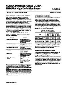
Building a Look Up Table (LUT) The next step is to build a Look Up Table (LUT) which will help ensure that digital prints resemble optical prints made from the same color negative. This procedure is also sometimes referred to as "linearizing the scanner." Note: The Look Up Table is referred to as the Color Table on the Calibrate screen in the box that says "Building Color Tables." 5. Insert the KODAK PROFESSIONAL PORTRA Scanner Control Negative (Size 120), (Cat. No. 137-9460) in the gate and click OK. 6. The software will scan the Scanner Control Negative and then display the scanned image.
March 15, 2000
9
KODAK PROFESSIONAL Device Calibration Software
Building a Look Up Table (LUT) (continued)
Note: The image should appear as above. 7. On the displayed image, locate and mark three corners of the gray patch target with the cursor (upper left, upper right and lower right). The software will mark a square in the center of each patch. 8. When the squares appear to be properly centered in each patch, click on the Accept button. If the squares are not properly centered, rescan the negative and try again. 9. Once the software has calibrated your scanner to the target, “Color balance is complete” will be displayed at the upper left corner of the screen. The slider values for Brightness, Red, Green, Blue, and Contrast are displayed to the left of the image.
10
March 15, 2000
KODAK PROFESSIONAL Device Calibration Software
Building a Look Up Table (LUT) (continued)
Slider values
Accept button
Note: In the illustrations of the Scanner Control Negative, one patch is surrounded by a white border (see red circled patch above). This is sometimes referred to as Patch #6. The Patch and Patch Aim values refer to the values for this patch. 10. Compare the values in the Patch field to those in the Patch Aim field. If these are not within 02 of their respective aims and 03 of each other, rescan the target or rerun the calibration routine. Note: For the following procedure you will need the Balance Point for FilmType Worksheet. See Appendix D: Balance Point for FilmType Worksheet, p. 33 for an example. The FilmType name (e.g., Kodak PORTRA) can be found in the pull-down menu on the LR_Scanner1 window. 11. On the Balance Point for FilmType Worksheet, record the Patch Aim values and the Slider values for the FilmType. These will be necessary to create new settings. Sample worksheet: FilmType name (exactly as it appears in popup menu)
Primary
March 15, 2000
PORTRA_KPRO
Scanner Codes
Corrections
(Patch Aims)
(Slider Values)
R
G
B
B
107
105
106
-7
R 0
G
B
-2
-1
C 0
11
KODAK PROFESSIONAL Device Calibration Software
Building a Look Up Table (LUT) (continued) 12. If the target image and the values are acceptable, click on the Accept button. The window displaying the data or Look Up Table (LUT) will be displayed. Look for large aberrations in the measured data. Rescan if necessary to match Aim as closely as possible. Note: The line on the screen represents the Aim values. Aberrations are indicated when the color blocks representing the Patch values of the scanned image form a curve that is greatly different from the line. The following illustration represents an acceptable LUT.
13. If the LUT is acceptable, click OK to save the Look Up Table.
12
March 15, 2000
KODAK PROFESSIONAL Device Calibration Software
Saving the Look Up Table (LUT) in the Long Roll Scanning Software To use the data generated by the Device Calibration Software with the Long Roll Scanning Software you must save this information so that the Long Roll Scanning application can access the correct LUT during daily calibration and scanning. 1. When you click OK to save the LUT, the following screen will be displayed.
2. Select the CompositeMachine Folder on your hard drive. 3. Select the Tables folder. 4. Select the ScannerLUTs folder. If this is the first time, do the following: a. In the Tables folder, make a new folder called ScannerTables and then open it. b. Make 2 new folders: SlopeTables and ScannerLUTs. Note: There should be no spaces in the folder names. 5. Enter the file name of the LUT. For example, RFS_S_PORTRA_date.LUT (S means Speed Up). 6. Click on SAVE. This will return you to the Device Calibration screen. You will now need to apply the LUT to be used for calibration and scanning.
March 15, 2000
13
KODAK PROFESSIONAL Device Calibration Software
Applying the Look Up Table (LUT) Once you have saved the LUT, you must launch the Long Roll Scanning software and apply the correct LUT to be used for daily calibration and scanning. Launching the Long Roll Scanning Software Note: Store the LR_Scanner folder on the hard drive. You can create an alias on the desktop for easier access. To launch the Long Roll Scanning software: 1. Double click on LR_Scanner folder. 2. Launch ScanEngine1. Note: Wait until "Idle" appears in the command bar. 3. Drag LR_Scanner1 to ScanEngine1. The following screen appears:
In the Long Roll Scanning Software screen (LR_Scanner1) enter the following settings:
14
•
Job and roll number (can be any alphanumeric characters for calibration)
•
Select RFS 3570/Sizzle or RFS3570 Plus
•
Select High V to maximize image area scanned
•
Choose Film type: PORTRA_KPRO
•
Set Film size to 62mm/6x7 for Printer Control Negative
•
Set ∆% at Zero (i.e., % of change from 62mm)
•
Set Sharpen to Off: left-hand Sharpen to 0, right-hand Sharpen to No
March 15, 2000
KODAK PROFESSIONAL Device Calibration Software
Applying the Look Up Table (LUT) (continued) •
Autobalance should NOT be selected
•
Enter starting DRGB values for the Normal negative for your lab (e.g., 64, 0, 16, 16) for both Reference and Actual values (or use your reference video analyzer values)
•
Enter starting BRGBC values using the Slider values from the Balance Point for FilmType Worksheet (e.g., as in the worksheet example page 11: -7, 0, -2, -1, 0) in Actual BRGBC only, leaving the Reference values at zero
Select the LUT you created using the Device Calibration software: 1. Click on the Select LUT button. The following screen appears for selecting the LUT. Check to be sure the path is: BigHD \ CompositeMachine \ Tables \ ScannerTables \ ScannerLUTs.
2. Select the newly saved file RFS_S_PORTRA_date.LUT. 3. Click on the Open button. Once complete, the LUT will be displayed in the LR_Scanner1 window. 4. Click on the Save Settings As button. 5. Save in the BigHD \ LR_Scanner_Settings folder. Name the file Calmaster_PORTRA. 6. Also click on the Save Settings button to save the settings to the Preferences folder. 7. Scan the KODAK PROFESSIONAL PORTRA Scanner Control Negative using the new LUT.
March 15, 2000
15
KODAK PROFESSIONAL Device Calibration Software
Applying the Look Up Table (LUT) (continued) Note: It may be necessary to calibrate the scanner at this time. Follow the calibration instructions that appear on the screen. The scanned image is displayed next to the LR_Scanner1 window.
Verify that the LUT is active: 1. On the Target screen, compare the Patch values to the Patch Aim values to determine that the code values for Patch #6 are on aim. Note: Patch #6 is the patch surrounded by a white border. The Patch and Patch Aim values refer to the values for this patch. The Patch values can be seen on the bottom of the screen. They change according to the location of the cursor. Place the cursor in the Patch #6 to see the values for that patch. The Patch Aim values for Patch #6 were recorded on the Balance Point for FilmType Worksheet (see Appendix D: Balance Point for FilmType Worksheet, p. 33.) 2. If necessary, adjust the slider values (Actual DRGB) to get Patch #6 (±03) on aim. 3. If you have changed the slider values, check that all patch values are on aim (click on the window for each patch and note the values at the bottom of the screen - all should be within ±03 of the values on the Balance Point for FilmType Worksheet. 4. If any values have been changed, click on Save Settings As and save the LUT as Calmaster_PORTRA. 5. Also click on the Save Settings button to save the settings to the Preferences folder.
16
March 15, 2000
KODAK PROFESSIONAL Device Calibration Software
Applying the Look Up Table (LUT) (continued) Without Video Analyzer: If you are using digital equipment without a video analyzer and do not intend to use analyzer data, the calibration is complete. Additional refinements or corrections can be made to the scanned images at any time by re-calibrating the scanner or changing the color values in the Long Roll Scanning software. With Video Analyzer: If you are using the scanner with an optical system and video analyzer you can build Slope Tables at this time.
March 15, 2000
17
KODAK PROFESSIONAL Device Calibration Software
Building Slope Tables In a digital/hybrid system that integrates video-analyzer data, you should build Slope Tables to balance your system for under- and over-exposed negatives. This procedure takes place within the Long Roll Scanning application. Complete the following steps and then insert the values in the Device calibration software: Calculated and Required Values screens.
Setting up your Master Film Balance: PORTRA This procedure allows you to fine tune the scanner to the color preferences for your lab. For this procedure, you will need the KODAK PROFESSIONAL PORTRA Printer Control Negatives: •
Control Negative (Normal), Cat. No. 846-0958
•
Very Underexposed Negative (Very Under, U2), Cat. No. 107-1398
•
Underexposed Negative (Under), Cat. No. 841-1902
•
Overexposed Negative (Over), Cat. No. 177-1302
•
Very Overexposed Negative (Very Over, O2), Cat. No. 144-5741
You will also need the best optical print of the KODAK Printer Control Negative (Normal) from your lab for comparison purposes. If possible, read the Status A density of the center gray patch from this best print and use those values as a reference for adjusting the scanner output. 1. On the LR_Scanner1 window, click on the Load Settings button to load settings for your master scanner setup. Note: You should have entered the most popular film size and aperture for your lab in the Master Scanner Set Up folder during set up and installation of your scanner. 2. Place your Control Negative (Normal) into the scan gate. 3. Click on the Scan1 button. The following screen is displayed.
18
March 15, 2000
KODAK PROFESSIONAL Device Calibration Software
Setting up your Master Film Balance: PORTRA (continued)
4. Click on the gray patch on the screen and adjust the slider values (Actual BRGBC) until the code values displayed on the screen are at the desired aims ±02 for your optical control image. (The patch values can be seen on the bottom of the screen under the image. They change according to the location of the cursor.) You will have to convert your lab's print densities to the corresponding code values to be able to compare the aims. For example, if the print density was .75, .70, .70, the slider values should be adjusted to give code values of 105, 111, 111 on the screen’s gray patch, when the calibration process is done correctly. Use your lab’s Target Aim Print Densities. Check the Print Density to Code Value conversion table (G2.2/INV) for the correct values (path: KPIS \ Tables \ KodakCRT \ CRT Gamma Choices Full \ G2.2/INV.) See Appendix F: Print Density to Code Value Worksheet, p. 35, for an example of the Worksheet and Appendix G: G2.2/INV File, p. 36, for the complete table. Sample of Print Density to Code Value Conversion Table (CVS) Digital Code Value
R
G
B
69 70 71 72
112 111 110 108
112 111 110 108
112 111 110 108
Optical Print Densities
Note: C (Contrast) should not be adjusted during the balancing process. 5. Create a Reference Images folder on the hard drive (path: BigHD \ Reference Images \). 6. Click on the Save As button to save the image in the Reference Images folder.
March 15, 2000
19
KODAK PROFESSIONAL Device Calibration Software
Setting up your Master Film Balance: PORTRA (continued) 7. Click on New Folder and name it Balance. 8. Click on the Create button and then type in the filename (e.g., N_6,O,O,6,2_PORTRA_date - using the BRGBC values and filmtype as part of the name). This file will be printed. 9. Click on the Save Settings As button and save as the same name to add these offsets to your settings. 10. Also click on the Save Settings button to save the settings to the Preferences folder.
Comparing Scanner Output Values with Digital Print Output 1. Make a print of the digital file of the master film balance printer control negative (Normal) to the desired output device (LF CRT, KPDM, or LED). 2. Be sure that the correct output table is used to print to the desired device. (e.g., path: BigHD \ CompositeMachine \ Tables \ KodakCRT \ FullRange \ Gamma2.2/INV.) 3. Compare this print (digital) to the master (optical) reference print. 4. Determine the needed corrections visually or use a densitometer. Note: Make sure your processing equipment is in Control. The densitometer must be a known, calibrated densitometer. 5. Adjust the slider values (Actual BRGBC) on the LR_Scanner1 window to the desired settings.
20
•
Use the brightness (B) if the overall density is equally light or dark.
•
Adjust the slider values so that the code values will equal the desired print density.
•
Use the individual slider values to match the individual desired code values. (Stay consistent with the rest of the lab where everything is normalized to red = 0.)
•
A one-slider value change can result in as much as a 3 to 5 code value change (print density).
•
Re-scan the control tool each time a slider value change is made and check the gray patch density; adjust the slider value, re-scan, and check the gray patch values until they are on aim.
•
Record the new aim code values in the Balance Point for FilmType Worksheet (see Appendix D: Balance Point for FilmType Worksheet, p. 33 for an example); the differences from the original aims are offsets or preferences which make the digital print match the optical print.
•
Click the Save button on the LR_Scanner1 window and save the image to the Reference lmages \ Balance folder you created earlier.
March 15, 2000
KODAK PROFESSIONAL Device Calibration Software
Comparing Scanner Output Values with Digital Print Output (continued) 6. Print the digital file of the master film balance printer control negative (Normal) again to verify the changes. 7. Compare the digital print to the optical print. If it is not acceptable, repeat steps 5 and 6. 8. If the image is acceptable, this becomes the master reference digital print. 9. Once on aim, enter the Actual BRGBC values into the Reference BRGBC line on the LR_Scanner1 window. 10. Click on the Save Settings As button and save using the same name. 11. Also click on the Save Settings button and save to the Preferences folder. When prompted to cancel or replace, click Replace.
March 15, 2000
21
KODAK PROFESSIONAL Device Calibration Software
Calibrating the Monitor 1. Adjust the monitor to match the digital reference print. Make sure the lighting condition of the print and monitor are the same (preferred viewing lights). 2. Use the Knoll Gamma routine in Adobe Photoshop to make adjustments.
22
March 15, 2000
KODAK PROFESSIONAL Device Calibration Software
Collecting Information to Create Slope Tables from KODAK Long Roll Scanning Software Note: Make sure Slope is not active for this part of the procedure. Slope is active when the box next to Slope has a check mark on the LR_Scanner1 window. If there is a check mark in the box, click on the box to remove it. For this procedure you will need the Slope Table Worksheet. See Appendix E: Slope Table Worksheet, p. 34 for an example. You will also need the KODAK Printer Control Negatives: •
Control Negative (Normal), Cat. No. 846-0958
•
Very Underexposed Negative (Very Under, U2), Cat. No. 107-1398
•
Underexposed Negative (Under), Cat. No. 841-1902
•
Overexposed Negative (Over), Cat. No. 177-1302
•
Very Overexposed Negative (Very Over, O2), Cat. No. 144-5741
Note: The values that appear in the Reference BRGBC slider value fields are based on your master film balance printer control negative (Normal). These values were entered during the procedure to set up your master film balance. See Comparing Scanner Output Values with Digital Print Output, step 9.
1. Place the Very Under (U2) negative in the scan gate. 2. Enter the values for very underexposed negatives: a. Enter the standard values used by your lab for very underexposed negatives into the Actual DRGB slider value fields on the screen. b. Click on the Actual BRGBC button. c.
Record the Actual BRGBC values from the screen into the Calculated Corrections area on the Slope Table Worksheet for the Under (U) negative.
d. Record the Contrast Value ( C ) in the Contrast Value box on the worksheet. Important: The Contrast Value (C) should not be modified at any time other than during the initial photographic calibration on the Normal control negative. Note: Although this value currently does not change, it is useful to record it.
March 15, 2000
23
KODAK PROFESSIONAL Device Calibration Software
Collecting Information to Create Slope Tables from KODAK Long Roll Scanning Software (continued) 3. Click on the Scan1 button to scan the negative. The following screen is displayed:
4. Match the scanned image to your optical control image for the Very Under (U2) print. Do this by adjusting the Actual BRGBC slider values for a visual or measured match. Measured Match: The gray patch code values can be used for adjustment purposes. Make adjustments to the Actual BRGB values, reading the gray patch code values between each adjustment. (The patch code values can be seen on the bottom of the screen. They change according to the location of the cursor.) Match the patch code values to those of the Control Negative (Normal). This is a good way to start if you are way out. 5. When this match is achieved, record the Actual BRGB numbers from the screen to the worksheet in the Required Corrections area in the row labeled Very Under (U2). 6. Repeat Steps 1 - 5 above for the Under (U), Over (O), and Very Over (O2) negatives. The data for both the Calculated Corrections and Required Corrections is required to generate an accurate slope table. 7. Generate prints of the control negatives using the Calculated and Required numbers entered for each test negative. If changes are required, adjust the Actual BRGB values based on the required change. Be sure to update the worksheet with the final numbers.
24
•
Compare the digital Very Under to the optical Very Under. If there is a difference, record the necessary changes.
•
Compare the digital Under to the optical Under. If there is a difference, record the necessary changes.
March 15, 2000
KODAK PROFESSIONAL Device Calibration Software
Collecting Information to Create Slope Tables from KODAK Long Roll Scanning Software (continued) •
Compare the digital Over to the optical Over. If there is a difference, record the necessary changes.
•
Compare the digital Very Over to the optical Very Over. If there is a difference, record the necessary changes.
•
Adjust the slider values for the desired corrections and record the new required slider values.
•
Rescan the Very Under, Under, Over, and Very Over negatives and save the new images to be printed.
•
Print the Very Under, Under, Normal, Over, and Very Over digital images again.
•
Make the necessary corrections, if any, and repeat the process until they are acceptable.
8. When the values are acceptable, enter them into the slope table program.
March 15, 2000
25
KODAK PROFESSIONAL Device Calibration Software
Entering Slope Table Values To use this portion of the software you must already have identified the scanner code values for under- and overexposed negatives. These values were determined during the previous procedures for building Slope Tables. Use the values recorded on the Slope Table Worksheet to enter values in the Calculated and Required Values screens. 1. Click on the Building Slope Tables icon in the upper right of the Device Calibration screen.
The Calculated Values screen will be displayed.
2. Enter the Calculated Corrections values from the Slope Table Worksheet. Click OK.
26
March 15, 2000
KODAK PROFESSIONAL Device Calibration Software
Entering Slope Table Values (continued) The Required Values screen will be displayed.
3. Enter the Required Corrections values from the Slope Table Worksheet. Click OK. A graph showing the slope curve and values will be displayed.
Activating Slope Tables To use the data generated by building the Slope Table, you must save the Slope Table so that the Long Roll Scanning Software can access it during daily calibration and scanning. Save the Slope Table in the SlopeTables folder (path: BigHD \ CompositeMachine \ Tables \ ScannerTables \ SlopeTables). Saving the Slope Table 1. When the Slope Table is displayed, in the File menu select Save As. The Save As screen will be displayed. The File Name will be untitled.tbl. 2. Go to the SlopeTables folder (path: BigHD \ CompositeMachine \ Tables \ ScannerTables \ SlopeTables). 3. Rename the table to match the FilmType and click Save. Important: The file name must match the FilmType in the pull-down menu on the LR_Scanner1 window exactly (e.g., PORTRA_KPRO).
March 15, 2000
27
KODAK PROFESSIONAL Device Calibration Software
Opening the Slope Table Make the LR_Scanner1 window the active window. 1. On the LR_Scanner1 window, check to select the Slope box near the Actual slider values. 2. Click on the Actual BRGBC button. A directory screen will be displayed. 3. Locate the Slopetables folder. The list of slope tables will be displayed. Note: This applies to the first Slope Table. When you perform this process again, you must delete the path defined in the LR_Scanner1.pref file prior to launching the Long Roll Scanning Software. 4. Select the file with the correct "FilmType" name and click Open.
28
March 15, 2000
KODAK PROFESSIONAL Device Calibration Software
Appendix A: System Calibration (Digital/Hybrid Systems) System calibration is not a single event. It is a series of refinements and/or decisions about how you want the final image to look. KODAK PROFESSIONAL Device Calibration Software is one part of calibrating your system. Labs matching a digital or digital/hybrid system to their optical system must insure that the optical system is optimized first. The data from your digital/hybrid system can and should be driven by the data from your video analyzer. For the Master printer, check to make sure that: • • • • • • •
The printer is set up to dead heat for the Master film, paper, size, and Printer Control Negatives. Optical components are clean and in good working order. This includes the cold mirror, lens assembly, integrator, diffuser, cutoff filters, and balancing filters. Master Control reference print is on aim, visually - within lab tolerances. The filter table edit routine from the Accudata Controller has been used and selected. The correct reciprocity values are being used. Slope (correction) values for density or any one color are within reason. (±3.0 for 3 Point Slope or ±6 for 5 Point Slope). The required KCES negatives have been set up to be printed and the TM values have been generated. These values should be between 85 and 115 for TMs 5 and 9. TMs 6 and 8 should be between –07 and +07.
For the Master Video Analyzer, check to make sure that: • • • • •
The machine matrix has been derived recently. The aim points for the Master Film’s Control set are set correctly. The film matrix values for the Master Film/Paper (Portra III) are set correctly. Contrast and brightness are set to match the monitor. The image you see on your screen of the Printer Control Negative visually matches the Control print at the printed DRGBs.
When you have an acceptable Master Reference Print, measure the densities of the gray patch using a densitometer. The densitometer must be a known, calibrated densitometer. Record these values. These values may be different from Kodak’s recommended starting point because of individual lab preferences. Important: The processor must be in good, if not excellent, Control. For the digital output device, check to make sure that the device is: • • •
Set up Balanced Calibrated
Print the standard Printer Control Negative (Normal) image until the output device is on aim. The scanner can be optimized once the optical system is correct and the digital output device is on aim. The Master or Reference prints from both the optical and digital output devices should match.
March 15, 2000
29
KODAK PROFESSIONAL Device Calibration Software
Appendix B: Assumptions The scanner set up and system calibration procedure assumes:
30
•
Labs matching a digital/hybrid system to an optical system have optimized the optical system first and are using a satisfactory Master or Control print.
•
The digital output device has been calibrated, set up, and balanced as recommended and the Standard Control Tool is on aim.
•
You are using the KODAK PROFESSIONAL Scanner Control Negative with this software. This tool is used for system balance and calibration procedures.
•
Your scanner’s power is on, and the scanner is ready for calibration.
•
KPIS for the Macintosh is installed.
•
The KODAK Long Roll Scanning Software is resident on the hard drive that will run the scanner
•
Your monitor has been calibrated to match your digital output. Use the Gamma Knoll Software supplied with Adobe Photoshop.
March 15, 2000
KODAK PROFESSIONAL Device Calibration Software
Appendix C: Setting Film Type and Size The KODAK PROFESSIONAL Device Calibration Software has been configured to use the following defaults: •
Film Type: PORTRA_KPro
•
Film Size: 62mm/6x7
The scanner is then calibrated using the KODAK PROFESSIONAL PORTRA Scanner Control Negatives (size 120), Cat. No. 137-9460. If you need to calibrate the scanner to a different film type or film size, you must change the parameters in both the settings.dft file and the Target_AIMS file. Note: You must have the correct Scanner and Printer Control Negatives for the film type selected to calibrate the scanner properly.
Changing the Settings.dft file The Settings.dft file sets the parameters for film type and size. Defaults are: •
Film Type: PORTRA_KPro
•
Film Size: 62mm/6x7
1. Locate the settings.dft file (path: Kodak Device Cal App \ Templates \ 3570 Scanner Speed Up \ Config \ Settings.dft). 2. Drag and drop the settings.dft file on a text editor. 3. Edit the settings.dft file to select the correct film type and film size. Note: To select a parameter, remove the '#' in front of the selection. Make sure only one parameter is selected. If another one was previously selected, type the '#' in front of the parameter to remove the selection. •
Type the # in front of the previously selected Target Film Type and Film Size
•
Locate the appropriate Target Film Type and remove the # from the selection
•
Locate the appropriate Film Size for the negative and remove the # from the selection
4. Save and close the file.
March 15, 2000
31
KODAK PROFESSIONAL Device Calibration Software
Changing the Target_AIMS File The Target_AIMS file identifies the AIMS parameters for calibrating your scanner. To access the correct AIMS parameters, the Target_AIMS file for the film type used in the scanner must be loaded. Defaults are: •
Film Type: PORTRA_KPro
•
Film Size: 62mm/6x7
To change the Target_AIMS file parameters: 1. Locate the folder created for your scanner (path: BigHD \ Devices \ "ScannerName"). See, Creating a New Device, p. 6 for information on naming the device. 2. Select the appropriate Target_AIMS file and open it.
3. From the File menu, select Save As. Change the name to Target_AIMS and click Save. When prompted to replace or cancel, click Replace.
32
March 15, 2000
KODAK PROFESSIONAL Device Calibration Software
Appendix D: Balance Point for FilmType Worksheet Balance Point for FilmType WORKSHEET FilmType name *
Scanner Codes (Patch Aims) R G B
B
Corrections (Slider Values) R G B
C
Primary
* Enter FilmType name exactly as it appears in pull-down menu on LR_Scanner1 window.
March 15, 2000
33
KODAK PROFESSIONAL Device Calibration Software
Appendix E: Slope Table Worksheet Use this worksheet to record values to use in building slope tables. LONG ROLL SLOPE TABLE WORKSHEET
Date:
Customer Name:
Scanner ID:
Film Type:
Slope Table File Name:
Calculated Corrections Negative
Brightness Red
Actual CVs
Green Blue Red
Video-Analysis Data
Green Blue Density Red
Green Blue
Normal Very Under (U2) Under (U) Over (O) Very Over (O2)
Contrast Value
Required Corrections Negative
Brightness Red
Actual CVs
Green Blue Red
Video-Analysis Data
Green Blue Density Red
Green Blue
Normal Very Under (U2) Under (U) Over (O) Very Over (O2)
Actual CVs are Code Values taken from the screen. Video-Analysis Data is taken from use of the video analyzer in the lab.
34
March 15, 2000
KODAK PROFESSIONAL Device Calibration Software
Appendix F: Print Density to Code Value Worksheet Use this worksheet or something similar to record conversion values for your lab. Gamma 2.2 Full range Print Density to Code Value Aims Usage: Find the desired print density in the Print Density column. Go left one column and find the corresponding code value. Code Value 71 72 73 74 75 76 77 78 79 80 81 82 83 84 85 86 87 88 89 90 91 92 93 94 95 96 97 98 99 100 101 102 103 104 105 106 107 108 109 110 111 112 113 114
March 15, 2000
Print Density 110 108 107 106 105 104 103 102 101 100 99 98 96 95 94 93 93 92 91 90 89 88 87 86 85 84 83 82 82 81 80 79 78 77 77 76 75 74 73 73 72 71 70 70
35
KODAK PROFESSIONAL Device Calibration Software
Appendix G: G2.2/INV File #Input Red Green Blue Black 0 1 2 3 4 5 6 7 8 9 10 11 12 13 14 15 16 17 18 19 20 21 22 23 24 25 26 27 28 29 30 31 32 33 34 35 36 37 38 39 40 41 42 43 44 45 46 47 48 49 50 51 52 53 54 55
36
255 254 253 252 250 248 245 243 240 237 234 231 228 224 221 218 215 212 209 206 203 200 197 195 192 189 187 184 182 179 177 175 172 170 168 166 164 162 160 158 156 154 152 150 148 147 145 143 141 140 138 137 135 134 132 131
255 254 253 252 250 248 245 243 240 237 234 231 228 224 221 218 215 212 209 206 203 200 197 195 192 189 187 184 182 179 177 175 172 170 168 166 164 162 160 158 156 154 152 150 148 147 145 143 141 140 138 137 135 134 132 131
255 254 253 252 250 248 245 243 240 237 234 231 228 224 221 218 215 212 209 206 203 200 197 195 192 189 187 184 182 179 177 175 172 170 168 166 164 162 160 158 156 154 152 150 148 147 145 143 141 140 138 137 135 134 132 131
March 15, 2000
KODAK PROFESSIONAL Device Calibration Software
56 57 58 59 60 61 62 63 64 65 66 67 68 69 70 71 72 73 74 75 76 77 78 79 80 81 82 83 84 85 86 87 88 89 90 91 92 93 94 95 96 97 98 99 100 101 102 103 104 105 106 107 108 109 110 111 112 113 114 115 116
129 128 126 125 123 122 121 119 118 117 116 114 113 112 111 110 108 107 106 105 104 103 102 101 100 99 98 96 95 94 93 93 92 91 90 89 88 87 86 85 84 83 82 82 81 80 79 78 77 77 76 75 74 73 73 72 71 70 70 69 68
March 15, 2000
129 128 126 125 123 122 121 119 118 117 116 114 113 112 111 110 108 107 106 105 104 103 102 101 100 99 98 96 95 94 93 93 92 91 90 89 88 87 86 85 84 83 82 82 81 80 79 78 77 77 76 75 74 73 73 72 71 70 70 69 68
129 128 126 125 123 122 121 119 118 117 116 114 113 112 111 110 108 107 106 105 104 103 102 101 100 99 98 96 95 94 93 93 92 91 90 89 88 87 86 85 84 83 82 82 81 80 79 78 77 77 76 75 74 73 73 72 71 70 70 69 68
37
KODAK PROFESSIONAL Device Calibration Software
117 118 119 120 121 122 123 124 125 126 127 128 129 130 131 132 133 134 135 136 137 138 139 140 141 142 143 144 145 146 147 148 149 150 151 152 153 154 155 156 157 158 159 160 161 162 163 164 165 166 167 168 169 170 171 172 173 174 175 176 177
38
67 67 66 65 64 64 63 62 62 61 60 60 59 58 58 57 56 56 55 54 54 53 52 52 51 51 50 49 49 48 48 47 46 46 45 45 44 44 43 43 42 41 41 40 40 39 39 38 38 37 37 36 36 35 35 34 34 33 33 32 32
67 67 66 65 64 64 63 62 62 61 60 60 59 58 58 57 56 56 55 54 54 53 52 52 51 51 50 49 49 48 48 47 46 46 45 45 44 44 43 43 42 41 41 40 40 39 39 38 38 37 37 36 36 35 35 34 34 33 33 32 32
67 67 66 65 64 64 63 62 62 61 60 60 59 58 58 57 56 56 55 54 54 53 52 52 51 51 50 49 49 48 48 47 46 46 45 45 44 44 43 43 42 41 41 40 40 39 39 38 38 37 37 36 36 35 35 34 34 33 33 32 32
March 15, 2000
KODAK PROFESSIONAL Device Calibration Software
178 179 180 181 182 183 184 185 186 187 188 189 190 191 192 193 194 195 196 197 198 199 200 201 202 203 204 205 206 207 208 209 210 211 212 213 214 215 216 217 218 219 220 221 222 223 224 225 226 227 228 229 230 231 232 233 234 235 236 237 238
31 31 30 30 29 29 28 28 27 27 26 26 25 25 25 24 24 23 23 22 22 21 21 21 20 20 19 19 18 18 18 17 17 16 16 16 15 15 14 14 14 13 13 12 12 12 11 11 10 10 10 9 9 8 8 8 7 7 7 6 6
March 15, 2000
31 31 30 30 29 29 28 28 27 27 26 26 25 25 25 24 24 23 23 22 22 21 21 21 20 20 19 19 18 18 18 17 17 16 16 16 15 15 14 14 14 13 13 12 12 12 11 11 10 10 10 9 9 8 8 8 7 7 7 6 6
31 31 30 30 29 29 28 28 27 27 26 26 25 25 25 24 24 23 23 22 22 21 21 21 20 20 19 19 18 18 18 17 17 16 16 16 15 15 14 14 14 13 13 12 12 12 11 11 10 10 10 9 9 8 8 8 7 7 7 6 6
39
KODAK PROFESSIONAL Device Calibration Software
239 240 241 242 243 244 245 246 247 248 249 250 251 252 253 254 255
6 5 5 4 4 4 3 3 3 2 2 2 1 1 1 0 0
6 5 5 4 4 4 3 3 3 2 2 2 1 1 1 0 0
6 5 5 4 4 4 3 3 3 2 2 2 1 1 1 0 0
Color Matrix Data Red Green Blue 256 0 0
40
0 256 0
0 0 256
March 15, 2000