Background Suppression Sensing at the Foreground of Demand
U
sing a wide-angle camera lens to take a group picture of people at your family reunion makes sense. But using the same lens and settings to take a close-up of your child’s face doesn’t. Sometimes the special moments in life call for different technologies to capture them, otherwise the images are ruined, and the chance to capture the memory is lost.
Before BGS sensing is explained, a simple definition of photoelectric sensing is helpful. A photoelectric sensor emits light. When something enters the area of that emitted light, it changes the light in some way, such as by obstructing it or by reflecting it differently. The sensor’s receiver detects that change, and the sensor’s output switches to indicate that something is present.
Sensing, likewise, bears best results when using specific technologies in certain applications. Using the wrong type of sensor can culminate in envelopes not being counted correctly, machine parts not being error-checked, or conveyor traffic that is not properly regulated.
Diffuse sensors in particular work on brute force. They blast out large amounts of light expecting something in the light’s path to reflect that light back to the sensor’s light-sensitive receiver. Some objects reflect a lot of light, while others reflect very little or even no light. When only the same reflective object is in the application environment and nothing else, they can be adequate. But they’re not only inefficient but also imprecise and impractical for other applications.
In years past, the options for photoelectric sensing were limited. In many instances, sensors had to be handled with kid gloves—constantly prodded, tweaked, and cajoled to do their jobs. If a sensor detected something it shouldn’t or didn’t see something it should, it meant the sensor had to be repositioned, readjusted, or replaced.
Part No. TDOCT-B0D0_ENG
Enter background suppression sensing as a remedy. From its earliest inception in the late 1970’s to the evolved technology of today, background suppression—also called BGS— has come a long way. Consequently, the use of BGS sensing has experienced a sharp rise in use compared to conventional sensing technologies in the last decade. This is partly because the technology needed time to catch up to and exceed application requirements. But also because the message of what makes BGS valuable began to reach more users.
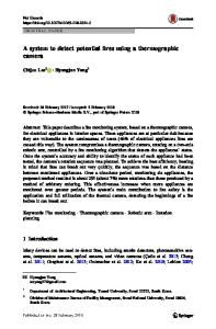
A conventional photoelectric sensor detects based solely on the intensity, or amount, of light reflected to its receiver. In one condition, the sensor’s receiver sees a smaller amount of light, and in another condition, it sees a larger amount of light. The sensor’s output changes to indicate which condition is present. However, background suppression sensors detect based on the triangulation of the reflected light. As shown in Figure 1, light from the sensor is reflected back at different angles based on the distance from the sensor. When something is close to the sensor, the angle is larger than when something is farther away. And because the angle of the reflected light changes, it results in the light reaching different parts of the sensor’s receiver. Figure 1: Triangulation of light for a background suppression (BGS) sensor. Light from emitter E is reflected from a target in the sensing range at a greater angle than that of light that is reflected from a background in the suppression range. Based on the angle of reflected light, targets reflect to receiver R’s near element N and backgrounds reflect to receiver R’s far element F.
1
Background Suppression Sensing at the Foreground of Demand
So because BGS works mainly on where light is reflected instead of how much light is reflected— as is the case with conventional sensors—it is remarkably less sensitive to variations of objects’ reflectivity. But there are other valuable benefits to BGS sensing. The advantages of using sensors with BGS can be categorized into four areas. BGS simplifies sensing The only way for older conventional sensors to successfully detect some objects is to use retroreflective or thru-beam versions (see Figure 2), which require the use of corner-cube reflectors for the former or two sensor housings for the latter. But using these older mode sensors can complicate or extend a set-up or changeover. First, the older systems can be more costly. Retroreflective sensors require purchasing a reflector and mounting hardware, and thru-beam
systems can cost 40% or more than the cost of a BGS sensor, because two housings and two sets of mounting hardware and electrical connections are needed. Secondly, retroreflective sensors require additional installation time to mount the reflector, while thru-beam sensors require both additional installation and wiring time for the separate emitter and receiver housings. Even after the set-up, BGS remains a simpler sensing mode, as it is not necessary to reposition the sensor or readjust its sensitivity. With conventional diffuse sensors, it can be required to tweak the sensor’s sensitivity and position relative to the object to be sensed to compensate for its largely inefficient optical performance. This can create more time-consuming changeover when an object’s color and/or reflectivity changes. Ultimately, less time devoted to a BGS sensor in both set-up and changeover phases means it is a less costly sensor.
Part No. TDOCT-B0D0_ENG
Figure 2: Basic photoelectric sensing modes: (a) diffuse and BGS, (b) retroreflective, and (c) thru-beam
2
Background Suppression Sensing at the Foreground of Demand
BGS consistently senses Possibly the biggest hidden advantage in BGS sensing—and the one that reaps the most benefits for customers with dynamic processes or products—is its sensing consistency. It senses a brown carton and a white carton the same way, or a printed wrapper and an unprinted black wrapper and a shiny foil wrapper with the same performance. In other words, the sensor is virtually “color-blind.” See Figure 3.
Sensing consistency means variations in product texture, color, or reflectivity have negligible or even no change on the sensor’s optical performance. The practical meaning of this is profound. BGS provides the ease of use of a single housing diffuse sensor but with the consistent sensing only seen previously in retroreflective sensors.
Part No. TDOCT-B0D0_ENG
Figure 3: Sensing Consistency of BGS Sensors From the color extremes of white to black and everything in between, when a BGS sensor is programmed to a specific maximum distance, the color of the detected object has a negligible effect on the actual sensing distance.
3
Background Suppression Sensing at the Foreground of Demand
BGS precisely senses A BGS sensor inherently has a small light spot, often less than one-half or even one-third the size of its diffuse counterpart. This is a requirement of BGS sensors, as if the light spot is too large, then it can flood the receiver lens and cover both the sensor’s near and far receiver elements. When this happens, then the sensor cannot distinguish between an object that is near or far, as the amount of light that falls on either element is equal to the other, and the comparator sees no difference between the two. There are definitive application benefits to having a small and bright light spot. A big plus is that the size of objects that can be detected is decreased, which means more object sizes can be seen by a BGS sensor than by a diffuse sensor. As an object to be seen should never be smaller than the sensor’s light spot, diffuse sensors may not be able to sense some small objects. This is because a diffuse sensor works based on the intensity of reflected light, and a smaller object simply has less surface area to reflect light, resulting in a lower intensity signal seen by the sensor’s receiver. As a trigger sensor, BGS provides a very accurate and repeatable way to detect the leading edge of an object. Rather than using a retroreflective sensor with a beam size of 70 mm at a distance of 350 mm away, a background suppression sensor, which has a light spot size of 15 mm at the same distance, can be used. The BGS sensor detects objects that can be smaller in size (down to 15 mm in this case) with a more precisely defined ON point, as opposed to a retroreflective sensor.
Part No. TDOCT-B0D0_ENG
BGS ignores obstructions The most obvious benefit of BGS sensors is built into its very name. Simply put, BGS suppresses backgrounds. It is a way to ignore objects that appear behind what actually must be detected. Ignoring something in the background may be easier said than done using diffuse sensors. Often, the background is something that is integral to the machine, or the sensor must be squeezed into tight confines. Ignoring a shiny background
machine panel or a reflective conveyor belt may not be a possibility in the application, as there may just not be the room available to change where the sensor must be mounted. In such cases, it makes most sense to place a BGS sensor in the application so that whether the background is a problem today or may become one tomorrow, it will not be detected in either case. Application Examples After explanations of the strengths of background suppression sensing, it’s helpful to consider instances in which BGS was selected to replace older traditional sensing technologies. Example 1: Load Detection on Palletizer The first such example involves a palletizer manufacturer in the material handling industry. Their engineers were faced with the task of reliably detecting varying loads on pallets that are to be automatically shrink-wrapped. The position and height of the load determines where and how the wrap is applied. Their old solution of using magnetic sensors was manual and cumbersome, as magnets had to be re-positioned every time the load size varied. And test results of diffuse sensors were disappointing, as they observed inconsistent results when the pallet had brown corrugated cardboard boxes, white boxes, or black boxes. It was necessary to consistently detect all objects without using a reflector or thru-beam arrangement, which required mounting space that was not available on the equipment. Ultimately, a long-range BGS sensor of 2-meter maximum sensing distance was selected to detect all types of loads with consistency. It also meant that the sensor set-up was simplified, as it was done one time and did not need to be repositioned for varying loads. Not only was the number of sensors needed per palletizer reduced, but also the set-up and changeover time were minimized.
4
Background Suppression Sensing at the Foreground of Demand
Example 2: Leading Edge Trigger of Textiles Another company had been using conventional diffuse sensors for years as a trigger of the leading edge of textile in a processing machine. Sensing the leading edge sent a signal to the machine’s controller to initiate an action such as sorting or transferring the textile. They had adapted their machine so that the sensor did not see machine components under the textile, but they periodically experienced problems in which the diffuse sensor would not see very dark textiles, such as black or navy blue. These were nuisance problems, but they still resulted in lost productivity.
Part No. TDOCT-B0D0_ENG
Their engineering group evaluated and implemented use of fixed-range BGS sensors. The immediate benefit was the ability to reliably detect all colors with a precise trigger point. Having a fixed-range sensor meant that a “tamper-proof” sensing solution was in place with no controls, such as push buttons or potentiometers. Reliable and precise triggering meant the textiles were detected and transferred when they should be, and the nuisance misses became a thing of the past.
Example 3: Error-proofing stamped parts An automotive parts manufacturer need to confirm the presence of stamped holes and slots in metal parts. If the slots and holes were not present, the part should be rejected for re-work, otherwise it would result in a defective assembly. The size of the holes and slots could be as small as a fraction of an inch in size (< 25 mm). Retroreflective and thru-beam sensors were not possible, as there was no space to mount a reflector or receiver housing opposite the part. Standard diffuse sensors, even laser-based ones with small light spots, would often detect a portion of the machine or other components attached to the part. The manufacturer determined that a laser-based BGS sensor allowed them to detect gaps and holes as small as 3/16 inch (4 mm) without sensing something behind the hole. The benefits for them were that the backgrounds were not detected and that a wider range of hole sizes could be detected. While these examples offer glimpses into several industries, machines, and applications, BGS isn’t limited to one industry or application type. It can be and often is applied to a comprehensive list of other markets and applications, from parts counting in assembly to presence verification in pharmaceutical to board positioning in solar cell handling to low-level carton magazine detection in packaging. ◙
Jeff Allison, Product Manager – Photoelectric Sensing Pepperl+Fuchs, Inc., Twinsburg, Ohio
[email protected] 330.486.0100
5