Advances in Automatic Control
Use of inductive loops to transmit information to vehicles RĂZVAN ANDREI GHEORGHIU, IULIAN BĂDESCU, RADU ȘERBAN TIMNEA Transport Faculty, Department of Telematics and Electronics in Transports University POLITEHNICA of Bucharest 313, Splaiul Independenței, Bucharest ROMANIA
[email protected],
[email protected],
[email protected]; www.pub.ro Abstract: Modern vehicles have already many systems that allow the drivers to take better decisions regarding the route (such as navigation devices), to avoid accidents (such as blind spot alert systems), or to let the driver focus on the road instead of operating auxiliary equipment (such as automatic air conditioning system). But the driver should also have knowledge about the traffic conditions in the nearby area. Such information could be about the traffic light’s colour when the vehicle will arrive at a junction, if the area ahead is congested and other relevant data a traffic management system already has. In this article we will analyse the possibility of sending information to vehicles via one of the most used traffic detectors, the inductive loop. Key-Words: communications, wireless, WiFi, Bluetooth, Zigbee, urban traffic, traffic management system, inductive loop obtained about the surrounding environment: other vehicles, the road infrastructure, junctions, signalling times and so on. Vehicle-to-vehicle and vehicle-to-infrastructure communication systems are being studied in different implementations, but most of them implying additional equipment both in vehicles and in the road network system. This specialized infrastructure is usually not easy to implement, mainly due to the costs involved.
1 Introduction Information is very important in urban traffic management, both for vehicles and the system itself. The main data is obtained by traffic detectors, both in the pavement and on the road side and is used by traffic management algorithms to determine the best signalling times for the traffic recorded on the road network. The drivers of vehicles, on the other side, get the information by direct observation of traffic conditions, which lead to relatively slow reactions to sudden changes and make the accurate prediction of the traffic ahead nearly impossible. Is obvious that the drivers would benefit from the information the traffic management system has, but the communication between vehicles and infrastructure is complex and, usually, require special (expensive) equipment both in the vehicles and on the road side, without the immediate perspective of great benefits.
3 Problem Solution Inductive loops are already used by a lot of traffic management systems to detect number of vehicles passing over them. These are used for adaptive systems that can change the signalling times in junctions according to the real traffic recorded by the detectors. Inductive loops are used in two ways: at the entry of the junction – to let the traffic controller know the number of vehicles approaching and at the exit of the junction – to transmit to the next traffic controller the number of vehicles that are going in that direction. Considering this, inductive loops are used for the traffic management system to get the data needed for its algorithms. But, as these are already installed in most of the traffic networks that have traffic management systems, we propose to use them not only to obtain
2 Problem Formulation The information sent to the vehicles by traffic management system through road infrastructure would be very useful in taking the right decisions by drivers and helping avoid accidents. In addition, autonomous vehicles are being studied in a lot of projects and are getting closer to the final stage – being able to travel in real traffic. These vehicles need all the information that may be
ISBN: 978-960-474-383-4
299
Advances in Automatic Control
Loop inductance is:
traffic information, but also to send information from the system to vehicles. [1]
N NBA N 0 r HA 0 r N 2 A L I I I l (4) When a vehicle is sensed by the loop, a small decrease in the loop inductance occurs, which is detected by the electronics unit. The frequency range of typical electronics units is 20–60 kHz. Some units, that are able to provide vehicle classification, can operate at hundreds of kilohertz. Loop capacitance may cause the inductance sensed by the electronics unit to modify considerably with frequency if there are too many turns in the roadway loop. [2] This needs to be carefully planned in order to obtain the optimal sensibility of the detection system. Some of the most important parameters that can be calculated based on inductive loops data are [3]: a) Volume: V=N/T, (5) Where: V = detected vehicles/hour N = detected vehicle in time interval T = time interval [h] b) Occupancy:
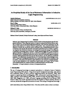
3.1 Inductive loops - basics The inductive loop detector system is made of one (or more) wire loops embedded in the pavement (which represent the sensing component), a splice between the lead-in wire and the lead-in cable in the pull box, a lead-in cable connecting to the terminal strip in the controller cabinet, a cable from the terminal strip to the inductive-loop electronics unit, and the electronics unit. The connections between these components are shown in Figure 1. [2]
(6) Where: θ = occupancy [%] T = time interval ti = total detector pulse time D = descendent slope time – ascendant slope time c) Speed:
Fig. 1 Inductive-loop detector system [2] The magnetic flow is evenly generated along the loop, except the end portions. The intensity of the generated magnetic flow is:
H
3,6 10 6 d v 5,280(t1 t0 )
NI l
-7
Based on the previous formula, the exact length of the vehicle can be deduced [3]:
5,280V 1 Lv t11 t10 t 21 t 20 6 2 3,6 10
(3)
(8) Where: v = previously established speed [km/h] ti0 = detection start time for detector i [ms] ti1 = detection end time for detector i [ms]
Where: 0 = 4 π10 [H/m] r = relative permeability of the material (being 1 for air) [H/m]
ISBN: 978-960-474-383-4
(7)
Where: v = vehicle speed [km/h] In case of using one detector: d = vehicle length + detector length [m] (vehicle length is considered as an average) t0 = detection start time [ms] t1 = detection end time [ms] In case of using two detectors: d = the distance between the two detectors t0 = detection start time for 1st detector [ms] t1 = detection start time for 2nd detector [ms]
(1) Where: H = magnetic flow intensity [A/m] I = electric current [A] N = coils number l = resistor length [m]. Because the generated magnetic flow is even, the magnetic flow is: BA (2) Where: ф = magnetic flow [Wb] B = magnetic flow density [T] A = loop section area [m2] The magnetic flow is dependent on the magnetic permeability:
B 0 r H
100 N (ti D) T i 1
300
Advances in Automatic Control
When the volume and the occupancy are known, speed is:
vC
V
t -
(9)
The occupancy time of an inductive loop, in seconds, is:
Lv 3.6 (10) v
Where: t = occupancy time [s] Lv = vehicle length [m] v = vehicle speed [km/h]. The time a vehicle is above the inductive loop is important to be considered because this is the interval the communication between vehicle and infrastructure may occur. There are 3 stages that can be identified: 1. The vehicle arrives above the detector; this causes the loop to react by decreasing its inductance. The electronic unit detects the modification and decide a vehicle was detected. 2. The electronic unit switch from reception (identification of changes in the loop circuit) to emission, in order to send information to the vehicle. 3. The actual communication infrastructure-tovehicle takes place. In order to evaluate the amount of data that can be sent, we first need to estimate the time available for the 4th stage. This is: tt t t r t s (11) Where: tt = transmit time t = total time the vehicle is over the loop tr = total receive time ts = switch time from reception to emission
3.3 Communication system The concept of communication system based on inductive loops came from the INDUSI principle, used for railways: for the first stage of the system’s implementation, there is only need to exchange little information, such as the colour of the traffic light when the vehicle will arrive at the next junction. A two inductive loop system may determine the vehicle’s speed and then, knowing its distance from the junction, the second loop may send to the driver the colour of the traffic light when the vehicle arrives at the junction, based on information obtained from the traffic management system. The faster the communication system will be the more information may be exchanged between the vehicle and the traffic management system. There are more solutions to implement the communication system. We shall focus on some protocols that are widespread used: Wi-Fi standard, Wi-Fi direct, Bluetooth and ZigBee.
Considering a medium length of a car Lv = 4.3 m we may estimate the total time the vehicle is over the loop for different speeds inside the city: - speed of 30 km/h:
t -
-
4.3 3.6 0.516s (12) 30
3.3.1 Wi-Fi protocol Wi-Fi protocol is set in the IEEE 801.11 standards family. It was first defined in 1997 and further developed to allow faster communication between wireless equipment. Table 1 shows a brief history of IEEE 802.11.
speed of 40 km/h:
t
4.3 3.6 0.387 s (13) 40
speed of 50 km/h:
ISBN: 978-960-474-383-4
4.3 3.6 0.258s (15) 60
Thus, we may conclude that the time the vehicle is over the inductive loop is, most likely, between 0.258 and 0.516 seconds. We shall consider an average loop response time of 100 ms, an approximate from two examples of loop datasheets ([4], [5]) one very fast and one slower, which have tr of 10 ms and 150 ms. We also have to consider a delay in the control unit when switching from receive to transmit mode. We estimate this delay, ts, to be 50 ms. With these values, in worst case (maximum speed – minimum time), from (11) we get: tt 0.258 0.1 0.05 0.108s (16) Thus, the communication system will have to be able to transmit the information in 100 ms or less. In the next section we shall present the basics of a communication system that may be implemented for data transmission to the vehicles using inductive loops.
3.2 Inductive loops occupancy time
t
speed of 60 km/h:
t
Where: C = calibration coefficient, experimental determined.
4.3 3.6 0.3096s (14) 50
301
Advances in Automatic Control
Table 1. IEEE 802.11 standards family [6] Standard Description IEEE 802.11 Up to 2 Mb/s; 2.4 GHz IEEE 802.11a Up to 54 Mb/s; 5 GHz IEEE 802.11b Up to 11 Mb/s; 2.4 GHz IEEE 802.11g Up to 54 Mb/s; 2.4 GHz IEEE 802.11e New coordination functions for QoS IEEE 802.11f Inter-AP Protocol IEEE 802.11h Use of the 5 GHz band in Europe IEEE 802.11i New encryption standards IEEE 802.11n MIMO physical layer
We may consider a bandwidth of 20 MHz and a rate of 28.9 Mbit/s, which should not be hard to obtain. The amount of data that can be transmitted in 0.108 s is 3.1212 Mbit. There is a lot of data that may be included after the link is established. But the downside of Wi-Fi protocol is the four way handshake procedure that assures the accuracy of data being transferred. This requires time and reduces the amount of data that can be sent.
There are two operating modes for Wi-Fi standard: ad-hoc and infrastructure. The operating mode is selected during the configuration of the wireless station. For the first mode, wireless stations communicate directly with one another, following a peer-to-peer model. Such networks can be set up anywhere, which is especially useful in situations requiring a quick setup. The infrastructure operating mode requires one wireless access point (AP). A major role for an AP is to extend access to wired networks for the clients of a wireless network. All wireless devices trying to join must associate with the AP. [7] At the beginning of a communication, the Wi-Fi equipment will scan the available channels to discover active networks. If a network is found, it will be selected. If the network is operating in infrastructure mode the device authenticates itself with the AP and then associates with it. If security is implemented, a further authentication step takes place, after which the station can participate in the network. Wi-Fi is able to provide different degrees of quality of service, depending on the system required. It ranges from best effort to prioritise to the guarantee of services. For our analysis, we select for data transfer the WiFi 802.11n protocol, which is supported by many devices and has the characteristics shown in the next table.
Fig. 2 Four way handshake [8] The messages exchanged during the handshake are depicted in Figure 2 and explained below. To send a direct message to another node, the source node emits a Request To Send (RTS) packet, addressed to the intended destination. If that destination hears the transmission and is able to receive, it replies with a Clear to Send (CTS) packet. The initiating node then sends the data, and the recipient acknowledges all transmitted packets by returning an ACK (Acknowledgement) packet for every transmitted packet received. If specific data is sent, the transmission could be protected in order to ensure that the message only arrives to the intended receiver. WPS (Wi-Fi Protected Setup) was introduced and developed by the Wi-Fi Alliance to standardize and simplify ways of setting up and configuring security on wireless networks. [7]
Table 2 WiFi 802.11n data rate Frequency (GHz)
Bandwidth (MHz) 20
2.4/5 40
ISBN: 978-960-474-383-4
3.3.2 Wi-Fi direct protocol Wi-Fi Direct equipment can connect to each other without having to go through a typical access point, by embedding a software access point ("Soft AP"). This way, Wi-Fi Direct devices may establish their own ad-hoc networks. Wi-Fi Direct is also referred to as Wi-Fi peer-topeer or Wi-Fi P2P, as it functions in peer-to-peer mode.
Data rate per stream (Mbit/s) 7.2, 14.4, 21.7, 28.9, 43.3, 57.8, 65, 72.2 15, 30, 45, 60, 90, 120, 135, 150
302
Advances in Automatic Control
The protocol operates in the license-free band at 2.402–2.480 GHz. To avoid interfering with other protocols that use the 2.45 GHz band, the Bluetooth protocol divides the band into 79 channels (each one being 1 MHz wide) and changes channels, generally 1600 times per second. [9] There are two forms of Bluetooth wireless technology systems: Basic Rate (BR) and Low Energy (LE). Both systems include device discovery, connection establishment and connection mechanisms. The Basic Rate system offers synchronous and asynchronous connections with data rates of 721.2 kbps for Basic Rate, 2.1 Mbps for Enhanced Data Rate (EDR) and high speed operation up to 54 Mbps with the 802.11 AMP. The LE system includes features designed to enable products that require lower current consumption, lower complexity and lower cost than BR/EDR. The LE system is also designed for use cases and applications with lower data rates and has lower duty cycles. [9] Considering the maximum theoretical data rate of 2.1 Mbit/s, the amount of data that can be transmitted in 0.108 s is 232.2432 kbit. Bluetooth provides a quick connection method and, with some optimisations of the messages being sent, enough data rate to send the defined information to the vehicles.
When a device enters the range of the Wi-Fi Direct host, it can connect to it, and then gather setup information using a Protected Setup-style transfer. Connection and setup is very simplified and is intended to replace Bluetooth in some situations. This protocol reduces the initial setup to a minimum and, hence, it is preferable to Wi-Fi standard for infrastructure-to-vehicle communication. 3.3.3 Bluetooth protocol Bluetooth technology was defined in 1994, by Ericsson Mobile Communications. The goal was to obtain a low-power-consumption system for substituting the cables in the short-range area of its mobile phones and relevant accessories. Bluetooth was adopted by IEEE 802.15 working group and made an IEEE standard, namely IEEE 802.15.1. When a Bluetooth device is powered on, it tries to operate as a slave of an already running master device. It starts listening for a master’s inquiry for new devices and responds to it with its address. This phase is not necessary for very simple paired devices that are granted to know each other’s address. Once a connection is established, the devices can optionally authenticate each other and then communicate. Devices not engaged in transmissions can enter one of several power- and bandwidthsaving modes or tear down the connection. Master and slave can switch roles. Bluetooth security is divided into three modes: - Non-secure - Service Level enforced security (after channel establishment) - Link Level enforced security (before channel establishment). Authentication and encryption at the link level are handled by means of four basic entities: 1. the Bluetooth device address, a 48-bit unique identifier assigned to each device; 2. a private authentication key, which is a random number; 3. a private encryption key, also a random number; 4. a 128-bit frequently-changing random number, dynamically generated by each device. There are two security levels for devices: trusted and untrusted, and three levels defined for services: open services, services requiring authentication and services requiring both authentication and authorization.
ISBN: 978-960-474-383-4
3.3.4 ZigBee protocol The first ZigBee specifications were set on December 14, 2004. After more revisions, ZigBee PRO was defined in 2007. The ZigBee standard is built on IEEE 802.15.4 for packet-based wireless transport and enhances its functionality by providing flexible, extendable network topologies with integrated set-up and routing intelligence to facilitate easy installation and high resilience to failure. ZigBee networks also incorporate listen-beforetalk and rigorous security measures that enable them to co-exist with other wireless technologies (such as Bluetooth and Wi-Fi) in the same operating environment. The ZigBee standard operates in the 2400-MHz band, although it is possible to implement ZigBee networks in any other IEEE 802.15.4 bands. [10] ZigBee is very flexible and allow networks to be easily adjusted to changing needs by adding, removing or moving network nodes. The protocol is designed such that nodes can appear in and disappear from the network, making it very adaptable and proper for infrastructure-to-vehicle communication. Another big advantage of a ZigBee
303
Advances in Automatic Control
wireless communication protocol that could optimize the access time and provide the optimum balance between security and data exchanged between vehicles and infrastructure. Such a procedure may benefit from the advantages the protocols described in this article have. As all the calculus indicates, inductive loops may be used to transmit information to vehicles. Even though the vehicle speed is relatively high and there is little time available for the transmission, the modern communication techniques and devices allow the data exchange in these conditions. Such a system should be tested in laboratory and in real traffic conditions to determine the best communication method. The system may be further developed to allow bidirectional communication with the loops, in order for the vehicles to send useful information to the traffic management system, such as the direction it is going in the next junction, based on the in-vehicle GPS guidance system and other relevant data.
network is the ease with which it can be installed and configured. The configuration of the network depends on how the installed system has been developed. There are three system possibilities: pre-configured, selfconfiguring and custom. a) Pre-configured system: all parameters are configured by the manufacturer. The system is used as delivered and cannot be modified or extended. b) Self-configuring system: A system that is installed and configured by the end-user. The network is initially configured by sending "discovery" messages between devices. Some initial user intervention is required to set up the devices - for example, by pressing buttons on the nodes. Once installed, the system can be easily modified or extended without any re-configuration by the user - the system detects when a node has been added, removed or simply moved, and automatically adjusts the system settings. c) Custom system: A system that is adapted for a specific application/location. It is designed and installed by a system integrator using custom network devices. [10] The system is usually configured using a software tool. ZigBee and IEEE 802.15.4 employ some techniques to ensure reliable communications between network nodes, such as Data Coding, Listen Before Send procedure and Acknowledgements. All the reliability measures implemented allow a ZigBee network to operate even when there are other networks nearby using the same frequency band (ZigBee, Wi-Fi, Bluetooth, or other) without any interference. The raw Zigbee data rate is 250 kbit/s per channel in the 2.4 GHz band. That means that the amount of data that can be transmitted in 0.108 s is 27 kbit. This protocol has many advantages, mentioned above, but the data rate available may not be enough for some applications.
References: [1] BUREȚEA L. D., CORMOȘ A. C., NEMȚANU F. C., MINEA M. TIMNEA R. Ș., IORDACHE V. GHEORGHIU R. A., Sistem și metodă pentru asistarea în traffic a unui conducător de autovehicul, RO-BOPI 10/2013 [2] Lawrence A. Klein, Milton K. Mills, David R.P. Gibson, Traffic Detector Handbook, Third Edition—Volume II, Publication No. FHWAHRT-06-139 [3] Gheorghiu RA, Urban traffic optimisations, PhD Thesis, 2011 [4] http://www.elektronika.ba/843/inductive-loopvehicle-detector-v2-1/ [5] Clark Induction loop vehicle detector DB1 datasheet, http://www.clarksystems.co.uk/docs/datasheets /DB1_DATA_001.pdf [6] Ferro Erina, Potortì F., Bluetooth and Wi-Fi wireless protocols: a survey and a comparison, IEEE Wireless Communications magazine, 2004-06-30. [7] An Introduction to Wi-Fi, 019-0170 • 090409B, Printed in U.S.A., Digi International Inc. © 2007-2008 [8] http://www.wildpackets.com/resources/compen dium/wireless_lan/wlan_packets [9] Bluetooth SIG, BLUETOOTH SPECIFICATION Version 4.1, 2013 [10] ZigBee PRO Stack User Guide, © NXP Laboratories UK 2012, JN-UG-3048, Revision 2.4
4 Conclusion Although some technical aspects that may alter the communication, such as noise and interference was not discussed in this article, the communication protocols presented offer enough capabilities and reliability to transmit information through loops. In addition to already existing standards, a system developer could implement a proprietary
ISBN: 978-960-474-383-4
304