Spring 2010: Radio Frequency Integrated Circuits (TSEK03)
1/18
Tutorial-1 Low Noise Amplifier (LNA) Design Complied by Rashad M. Ramzan Objective: Low noise amplifiers are one of the basic building blocks of any communication system. The purpose of the LNA is to amplify the received signal to acceptable levels with minimum self-generated additional noise. Gain, NF, non-linearity and impedance matching are four most important parameters in LNA design. The objective of this tutorial is to outline the basic tradeoffs between different amplifying topologies w.r.t gain, NF and impedance matching. After this comparison it is concluded that inductor degenerated common source topology gives the best performance to meet the gain, NF, and impedance matching goals with minimum power consumption in case of narrow band designs.
Goals: After this tutorial, students should be able to •
Calculate the gain, input impedance and NF of common gate, common source, and shunt feedback amplifiers.
•
Understand the basic equations and tradeoff between different LNA topologies.
• Perform the calculation for inductor degenerated common source topology and understand the tradeoff between the gain, NF, and impedance matching. A supplement tutorial LNA lab is also part of this course which guides through different analyses to design a practical LNA.
Electrical Engineering Department (ISY), Linköping University
2/18
Spring 2010: Radio Frequency Integrated Circuits (TSEK03)
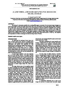
Problem-1.1(Tutorial) NMOS transistor is racing horse in LNA design arena due to its higher mobility compared to PMOS transistors. Calculate the IP3 of NMOS CS amplifier shown below. Assume that NMOS transistor is in saturation.
a) Consider simplified square law model. (HW)
ID =
Kn (VGS − VT ) 2 2
b) Consider the short channel effects as:
K n (VGS − VT ) 2 2 1 + θ (VGS − VT ) θ = Velocity Saturation, Mobility Degradation ID =
VGS − VT = 0.2V
and θ = 0.1V −1
Observe that this transistor is not a very “short channel” device as θ >1
Av ,tot =
− g m RL ≅ − g m RL RS 1 + g m RS + 1 + RL + RF RF
iin Vin
Av ,tot ≅ − g m RL Also
Z in =
RF + RL 1 + g m RL
By ignoring Cgs, we have considered real part only.
Electrical Engineering Department (ISY), Linköping University
Rs Vgs
RF
Vout gmVgs
RL
Spring 2010: Radio Frequency Integrated Circuits (TSEK03)
For source resistance
V 2 nRS ,out = A 2 v ,tot V 2 nRS
---------------(1)
For feedback resistance
RF V
Rs
i
2
V 2 RF ,out
RF
gmVgs
Vgs
RL
Vgs = −iRS = iRF − VRF + VRF ,out VRF ,out = RL (i − g mVgs ) VRF ,out = VRF
V
2
n , RF ,out
1 1+
RS + R F RL (1 + g m Rs )
= VRF
R = V n , RF L (1 + g m RS ) RF
RL (1 + g m RS ) RF
2
2
---------------------(2)
Similarly
Rs
i
VnD ,out RL
Vgs
gmVgs
+ I nD + g mVgs +
VnD ,out
Vgs = RS
VnD ,out =
V 2 nD ,out
RF
RS + R F
I 2 n,D
RL
=0
VnD ,out RS + R F
I n,D g R 1 1 + + m S R L RS + R F RS + R F
≈ I nD RL
So,
V 2 nD ,out = I 2 nD RL
2
------------------------------------------(3)
Combaining (1) (2) & (3) Electrical Engineering Department (ISY), Linköping University
8/18
9/18
Spring 2010: Radio Frequency Integrated Circuits (TSEK03)
F = 1+
R V 2 n , RF L (1 + g m R S ) RF
2
A 2 v ,tot V 2 n , RS
+
I 2 nD R 2 L A 2 v ,tot V 2 n , RS
Av ,tot = − g m RL , V 2 n , RS = 4kTRS ∆f , V 2 M ,RF = 4kTRF
1 1 + g m RS
R F = 1+ S RF
&
I 2 nD = 4kTγg m
2
γ + g m RS
b). NF
↓
gmRS ↑ & RF ↑ usually
RS = 50Ω
- Better performance than CS amplifier - RF induces noise - At higher f
↑
a shunt inductor needed to tune out Cgs
- Broadband Amp @ Lower frequency - To make NF
↓
RF > RS and gmRS >> 1
Problem-1.4 (HW) Common gate amplifier also offers 50 Ω input impedance match and solves the input matching problem.
c) Calculate the gain, input impedance and NF in absence of gate noise. Neglect gate drain and gate to bulk and gate to source capacitance. a) What are the disadvantage of common gate amplifier with reference to gain and NF?
Problem-1.5 (Tutorial) The disadvantages of the amplifiers discussed in Problem-2, 3 & 4 can be circumvented by using the source degenerated LNA shown below.
Electrical Engineering Department (ISY), Linköping University
10/18
Spring 2010: Radio Frequency Integrated Circuits (TSEK03)
a) Calculate the input impedance. This inductor source degenerated amplifier presents a noiseless resistance for 50Ω for input power match. How we can cancel the imaginary part of complex input impedance so that the LNA presents 50Ω real input resistance at input port. b) Calculate the NF in absence on gate noise. Neglect gate drain and gate to bulk and gate to source capacitance. c) Cgd bridges the input and output ports. The reverse isolation of this LNA is very poor. Why reverse isolation is important? Suggest the modification to improve reverse isolation.
Solution: a). VDD VS
Rs
Lg
iin
io
Vout
gmVgs Zin Vgs
Rs
VS
Vin Ls
Lg
RL Vout Ls
(Biasing not shown) From model above we can write
1 Vin = iin ( jωLg + jωLs ) + iin + io jωLs ---------------(1) jωc 1 io = g mVgs = g m iin × --------------------------------------(2) jωC gs Substituting (2) in (1)
g L 1 Vin = iin jω (Lg + Ls ) + + m s jωC gs C gs
Electrical Engineering Department (ISY), Linköping University
Spring 2010: Radio Frequency Integrated Circuits (TSEK03)
Z in =
11/18
Vin g L 1 = jω (Lg + Ls ) + + m s iin jωC gs C gs
Z in = jω (Lg + Ls ) +
g L 1 + m s jωC gs C gs
For matching Lg + Ls are canceled out by Cgs. So at frequency of interest
ωo (Lg + Ls ) = And
1 1 2 ⇒ ωo = ωo C gs (Lg + Ls )C gs
RS = 50Ω =
gm Ls C gs
Notes: a). Ls is typically small and may be realized by the bond wire for source. b). Lg can be implemented by spiral/external inductor.
b). Reference: For series RLC Circuit R L
From part a)
Z in = jω (Lg + Ls ) +
g L 1 + m s jωC gs C gs
We can draw this circuit as
Rs Vin Here
Q in =
gm
ω o (L g + L s ) RS +
Qin =
g m LS C gs
gm C gs
=
Ls C gs
ωo RS +
1 L ωo L 1 = = R C R ωo RC and VC = QSVin Qs =
Cgs Vgs
ω o (L g + L s ) R S + ω T LS
frequency of current gain equal 1
1
C VC
Lg + Ls Zin
Q ωT ≅
Vin
g m LS C gs
C gs
for match load
RS =
g m LS C gs
Electrical Engineering Department (ISY), Linköping University
12/18
Spring 2010: Radio Frequency Integrated Circuits (TSEK03)
1 2ω o Rs C gs
Qin =
Gain
Vgs = QinVin
Vout Rs
I g m = out V gs
Vin
Lg Vgs Zin
Ls
RL
I out V gs g m = = Qin g m V in V in
Gm =
G m = Qin g m
so,
V out = −G m R L where Gm = Qin g m Vin
Noise Figure:
F=
Total noise power at output noise power at output due to input source
For this calculation we ignore channel noise.
F=
V 2 nRS ,OUT + V 2 nD ,OUT V 2 nRS ,OUT
=1+
V 2 nD ,OUT V 2 nRS ,OUT
V 2 nD ,OUT = i 2 n ,D R 2 L
i 2 n , D = 4kTγg m ∆f
V 2 nRS ,OUT = V 2 n ,RS G 2 m R 2 L
V 2 n , RS = 4kTRS ∆f
i n2, D R L2
F = 1+ V
F = 1+
2 n , RS
2 in
2 m
Q g R
2 L
&
Gm = Qin g m
i 2 n , D = 4kTγg m , V 2 n , RS = 4kTRS
γ g m R S Qin2
Notes: - Very good NF value - Narrow band matching - NF
↓ with Q 2
- The Q is dependent upon Lg + Ls, Ls usually small so Q depends mainly upon Lg Electrical Engineering Department (ISY), Linköping University
13/18
Spring 2010: Radio Frequency Integrated Circuits (TSEK03)
C). Drawbacks i). VDD
VS
Rs
VDD RL generates noise so replace RL with LD so that’s
RL Vout
Lg
ωo =
1 LD C L
LD VS
Rs
CL
Lg
Ls
Ls
The CL can be considered the input capacitance of the following mixer or filter.
VDD
ii).
LD Reverse Isolation
Cgd
CL
Vb Rs
Vout
Lg Ls
Lo
(Final Design)
Reverse isolation depends upon capacitance between output and input. To make it less the cascode architecture can be used.
Problem-1.6 (HW) Fill-in the Table below, use the data from Problem-1.2, 1.4, 1.3 and 1.5
Type of LNA Shunt Resistor
Zin Rsh
Noise Factor
2+
4γ g m RS
Common Gate Shunt Feedback Source Degenerated
Electrical Engineering Department (ISY), Linköping University
Gain
− g m RL 2
NF (dB)
Spring 2010: Radio Frequency Integrated Circuits (TSEK03)
14/18
a) Calculate the NF for all above amplifiers. Assume γ=2, gm = 20mS, Rs = 50Ω, RF = 500Ω, and Qin = 2. b) Which is the best topology for Narrow Band LNA design at high frequency?
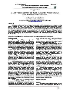
Problem-1.7 (Tutorial) Real Design: We will design the inductor-source-degenerated LNA shown in Fig below to meet the specification outlined for IEEE802.11b standard. The first cut approximate values are calculated as a starting point for simulation. LNA Specification: NF < 2.5 dB, Gain > 15dB, IIP3 > -5dBm, Centre Frequency = 2.4 GHz Load Capacitance = 1pF Technology Parameters for 0.35um CMOS:
Leff = 0.35µ m, µ n Cox = 170 µ A V 2 , Cox = 4.6 mF m2 , µ p Cox = 58 µ A V 2 , γ = 2
δ = 4, C = 0.395, α = 0.85
Solution:
Technology 0.35µm CMOS:
µ o Cox = 170 µA V 2 , µ p Cox = 58 µA V 2 , 2 Cox = 4.6 mF m , γ = 2, Leff = 0.35µm δ = 4, C = 0.395, α = 0.85
Design Parameters NF < 2.5 dB, Gain > 15dB, IIP3 > -5dBm, f0 = 2.4 GHz
Electrical Engineering Department (ISY), Linköping University
15/18
Spring 2010: Radio Frequency Integrated Circuits (TSEK03)
VDD RREF
LD
M3 RBIAS
M2 Vout
Lg M1
Vin
RS
CB
CL = 10pF
Ls
Component Description Ls – Matches input impedance Lg – Sets the Resonant Frequency fO = 2.4 GHz M3 – Biasing transistor which forms current mirror with M1 Ld – Tuned output increases the gain and also work as band pass filter with CL M2 – Isolates tuned input from output to increase reverse isolation, also reduces the effect of Miller capacitance Cgd CB – BC blocking capacitor chosen to have negligible reactance at fO = 2.4 GHz RBIAS – Large enough so that its equivalent current noise is small enough to be ignored. (Don’t consider it as voltage noise source. Why??)
Design Procedure Size of M1: From the noisy two-port theory (see the course book or lecture notes) the optimal input matching and minimum noise figure is given by:
Gopt = αω C gs Fmin = 1 +
(
)
δ 1 2 1− C = 5γ 50Ω
2 ω 5 ωT
(
γC 1 − C
2
----------------------(A)
) = 1 + 2.3 ωω
-------(B)
T
From (A)
C gs ≅ 2.7 pF ⇒ WM 1 ≈ 3C gs / 2COX Leff ≈ 2.5mm ( not feasible – huge size, huge power ! ) Conclusion: We will not go for the global minimum noise figure. Instead, we will look into the constraint power design approach. Solution: LNA NF will be optimized for given power which is higher than the global minimum NF. Electrical Engineering Department (ISY), Linköping University
16/18
Spring 2010: Radio Frequency Integrated Circuits (TSEK03)
In this case the optimum transistor width is given by:
Wopt =
1 3ωo Leff Cox RS
while the minimum power-constraint NF :
Fmin, p = 1 + 2.4
γ ω ω ⇒ Fmin, p = 1 + 5.6 α ωT ωT
---------------(C)
(B) is the global minimum noise figure. (C) is the minimum NF for a given power consumption. In practice the difference is usually 0.5dB to 1dB (no big deal for Lower Power)
Step - 1:
I1 = I 2 = 5mA (Limited Power consumption) Step - 2:
WM 1 =
1 3ω 0 L eff C ox R S
1 3 × 0.35µ × 4.6m × 50 × ωo
WM 1 =
RS = 50Ω, Cox = 4.6 mF m 2 , µ n Cox = 170 µA V , Leff = 0.35µm, ω = 2πf , f = 2.4GHz o o o
WM 1 = 3.9 × 10 −4 WM 1 = 3.9 × 10 −4 = 390µm Step - 3:
2 C gs1 = WM 1 Leff Cox 3 C gs1 =
2 × 390µ × 0.35µ × 4.6m = 0.41 pF 3
W g m1 = 2 µ n C ox I DM 1 L M1
or
g m1 =
2 I DM 1 V GS − VT
390 g m1 = 2 × 170µ × × 5m = 43 mA V 0.35
Electrical Engineering Department (ISY), Linköping University
(for short channel model)
17/18
Spring 2010: Radio Frequency Integrated Circuits (TSEK03)
ωT ≈
g m1 43 mA V = = 104G rad Sec C gs1 0.41 pF
Assuming Now
γ =2
Fmin = 1 + 5.6
Fmin = 1 + 5.6
ωo ωT
2π 2.4G ≈ 2.55dB 104G
NF ≈ 2.55dB This NF is very close to the specified value. If we increase ID then ωT should increase slightly as well and hence, a lower NF value can be achieved at expense of more power. Step - 4: Source and gate inductance such that they cancel Cgs and set
50Ω input impedance
ωo = 2πf o = 2π 2.4 = 15G rad Sec From previous problem R S = RTransformed =
LS =
RS
ωT
=
g m LS ≅ ω T LS C gs
50 ≅ 0.5nH 100G
LS = 0.5nH can be implemented using the bond wire. 1 L + L = g s Now ω 02 C gs1
Lg + Ls =
1 = 10.81nH (15G ) × 0.41 pF 2
Lg ≈ 10nH Step - 5:
Ld =
1 ωo 2C L
Ld =
1 ≅ 4.4nH (15G ) × 1 pF
Q C L = 1 pF
2
Ld = 4.4nH Electrical Engineering Department (ISY), Linköping University
18/18
Spring 2010: Radio Frequency Integrated Circuits (TSEK03)
Step - 6: Size of M3 is chosen to minimize power consumption
W M 3 = 70µm, R REF = 2kΩ ⇒ I 3 = 0.6mA R BIAS = 2kΩ
(Large enough so that it’s equivalent current noise can be neglected)
C B = 10 pF ( X C ≈ 6.6Ω
so good value @ 2.4G
XB =
Step - 7: Size M2 = M3 So that they can have shared Drain Area.. (Note: You will simulate same LNA circuit in LAB # 2)
Electrical Engineering Department (ISY), Linköping University
1 = 6.6Ω ) 2πf o C B